EP0695677A2 - Anordnung einer Magnetschienenbremse an einem Einzelachsfahrwerk - Google Patents
Anordnung einer Magnetschienenbremse an einem Einzelachsfahrwerk Download PDFInfo
- Publication number
- EP0695677A2 EP0695677A2 EP95112002A EP95112002A EP0695677A2 EP 0695677 A2 EP0695677 A2 EP 0695677A2 EP 95112002 A EP95112002 A EP 95112002A EP 95112002 A EP95112002 A EP 95112002A EP 0695677 A2 EP0695677 A2 EP 0695677A2
- Authority
- EP
- European Patent Office
- Prior art keywords
- brake
- rail
- chassis
- arrangement
- magnetic rail
- Prior art date
- Legal status (The legal status is an assumption and is not a legal conclusion. Google has not performed a legal analysis and makes no representation as to the accuracy of the status listed.)
- Granted
Links
Images
Classifications
-
- B—PERFORMING OPERATIONS; TRANSPORTING
- B61—RAILWAYS
- B61H—BRAKES OR OTHER RETARDING DEVICES SPECIALLY ADAPTED FOR RAIL VEHICLES; ARRANGEMENT OR DISPOSITION THEREOF IN RAIL VEHICLES
- B61H7/00—Brakes with braking members co-operating with the track
- B61H7/02—Scotch blocks, skids, or like track-engaging shoes
- B61H7/04—Scotch blocks, skids, or like track-engaging shoes attached to railway vehicles
- B61H7/06—Skids
- B61H7/08—Skids electromagnetically operated
Definitions
- the invention relates to the arrangement of a magnetic rail brake on a single-axle chassis, the chassis frame of which is elastically connected both to a wheel axle and to a body of a rail vehicle.
- chassis frame and the wheel axle perform vertical spring movements in relation to one another.
- chassis frame can tilt. Unwanted contact between a magnetic rail brake mounted in the low suspension and the top edge of the rail cannot be ruled out.
- the invention is accordingly based on the object of arranging a magnetic rail brake on a single-axle running gear in such a way that the aforementioned undesired contacts are reliably avoided.
- This object is achieved in that the brake magnets of the magnetic rail brake are held in their rest position by a pneumatic cylinder connected to the chassis frame in an occurring vertical and tilting movements of the chassis frame height above the top edge of the rail.
- the brake magnets of the magnetic rail brake reach their operative position with the upper edge of the rail only by venting the pneumatic cylinders and their own weight.
- a further embodiment of the invention is that the magnetic rail brake has drivers interacting with counterparts of the chassis frame.
- the chassis frame 1 of a single-axle chassis is elastically connected to a wheel axle 7 and a body of a rail vehicle in a manner not shown.
- the chassis frame 1 can carry out tilting movements corresponding to the elasticities of this connection about the center of the wheel axis 7 forwards or backwards, such tilting movements occurring especially when starting off and braking.
- vertical spring movements between the chassis frame 1 and the wheel axle 7 are possible.
- the single-axle chassis is equipped with a magnetic rail brake, the brake magnets 2 of which are connected to one another in the transverse direction by a conventional track holder (not shown).
- the brake magnets 2 are each suspended by a pneumatic cylinder 3 on a bracket 8 of the chassis frame 1, namely at a height above the top edge of the rail 6 that is greater than All vertical and tilting movements of the undercarriage frame 1 that occur during driving operation. This prevents undesired contact of the brake magnets 2 with the top edge of the rail 6.
- Relative movements between the magnetic rail brake and the chassis frame 1 are limited by drivers 4, which interact with counterparts 5 of the chassis frame 1.
- the electrical current is switched on and the pneumatic cylinders 3 are vented, the brake magnets 2, due to their own weight, coming into the operative position with the upper edge of the rail 6 - without having to overcome the pretensioning force of a spring known from other magnetic rail brakes.
- the braking force of the brake magnets 2 is exerted immediately upon contact with the top edge 6 of the rail.
Landscapes
- Physics & Mathematics (AREA)
- Electromagnetism (AREA)
- Engineering & Computer Science (AREA)
- Mechanical Engineering (AREA)
- Braking Arrangements (AREA)
- Body Structure For Vehicles (AREA)
- Handcart (AREA)
- Valves And Accessory Devices For Braking Systems (AREA)
- Dynamo-Electric Clutches, Dynamo-Electric Brakes (AREA)
Abstract
Description
- Die Erfindung betrifft die Anordnung einer Magnetschienenbremse an einem Einzelachsfahrwerk, dessen Fahrwerkrahmen sowohl mit einer Radachse als auch mit einem Wagenkasten eines Schienenfahrzeuges elastisch verbunden ist.
- Bei Einzelachsfahrwerken führen der Fahrwerkrahmen und die Radachse vertikale Federbewegungen zueinander aus. Neben diesen Vertikalbewegungen können aufgrund der Elastizitäten in der Anbindung des Fahrwerkrahmens am Wagenkasten, vor allem beim Anfahren und Bremsen, Kippbewegungen des Fahrwerkrahmens auftreten. Dabei sind unerwünschte Berührungen zwischen einer in Tiefaufhängung angebrachten Magnetschienenbremse und der Schienenoberkante nicht auszuschließen.
- Der Erfindung liegt demgemäß die Aufgabe zugrunde, eine Magnetschienenbremse an einem Einzelachsfahrwerk derart anzuordnen, daß die zuvor genannten unerwünschten Berührungen sicher vermieden werden.
- Diese Aufgabe wird erfindungsgemäß dadurch gelöst, daß die Bremsmagnete der Magnetschienenbremse in ihrer Ruhestellung jeweils durch einen am Fahrwerkrahmen angeschlossenen Pneumatikzylinder in einer auftretende Vertikal- und Kippbewegungen des Fahrwerkrahmens übersteigenden Höhe über der Schienenoberkante gehalten sind.
- Nach einer bevorzugten Ausführungsform der Erfindung gelangen die Bremsmagnete der Magnetschienenbremse lediglich durch Entlüften der Pneumatikzylinder und ihr Eigengewicht in ihre Wirkposition mit der Schienenoberkante.
- Um Relativbewegungen zwischen der Magnetschienenbremse und dem Fahrwerkrahmen in Fahrtrichtung zu begrenzen, besteht eine weitere Ausgestaltung der Erfindung darin, daß die Magnetschienenbremse mit Gegenstücken des Fahrwerkrahmens zusammenwirkende Mitnehmer aufweist.
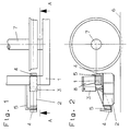
- Ein Ausführungsbeispiel der Erfindung ist in der Zeichnung schematisch dargestellt und im folgenden näher beschrieben. Es zeigen
- Fig. 1
- die Anordnung einer Magnetschienenbremse an einem Einzelachsfahrwerk in der Ansicht von oben,
- Fig. 2
- den Schnitt nach der Linie A - A in Fig. 1.
- Der Fahrwerkrahmen 1 eines Einzelachsfahrwerks ist in nicht dargestellter Weise elastisch mit einer Radachse 7 und einem Wagenkasten eines Schienenfahrzeuges verbunden. Der Fahrwerkrahmen 1 kann den Elastizitäten dieser Anbindung entsprechende Kippbewegungen um die Mitte der Radachse 7 nach vorne oder hinten ausführen, wobei solche Kippbewegungen vor allem beim Anfahren und Bremsen auftreten. Außerdem sind vertikale Federbewegungen zwischen dem Fahrwerkrahmen 1 und der Radachse 7 möglich.
- Das Einzelachsfahrwerk ist mit einer Magnetschienenbremse ausgerüstet, deren Bremsmagnete 2 durch einen üblichen Spurhalter (nicht dargestellt) in Querrichtung miteinander verbunden sind. Die Bremsmagnete 2 sind in ihrer Ruhestellung jeweils durch einen Pneumatikzylinder 3 an einer Konsole 8 des Fahrwerkrahmens 1 aufgehängt, und zwar in einer Höhe über der Schienenoberkante 6, die größer ist als alle im Fahrbetrieb auftretenden Vertikal- und Kippbewegungen des Fahrwerkrahmens 1. Eine ungewollte Berührung der Bremsmagnete 2 mit der Schienenoberkante 6 kann dadurch nicht vorkommen. Relativbewegungen zwischen der Magnetschienenbremse und dem Fahrwerkrahmen 1 werden durch Mitnehmer 4 begrenzt, die mit Gegenstücken 5 des Fahrwerkrahmens 1 zusammenwirken.
- Zum Aktivieren der Magnetschienenbremse werden der elektrische Strom eingeschaltet und die Pneumatikzylinder 3 entlüftet, wobei die Bremsmagnete 2 durch ihr Eigengewicht in die Wirkposition mit der Schienenoberkante 6 gelangen - ohne dabei die Vorspannkraft einer bei anderen Magnetschienenbemsen bekannten Feder überwinden zu müssen. Die Bremskraft der Bremsmagnete 2 wird bei Berührung mit der Schienenoberkante 6 sofort ausgeübt.
-
- 1
- Fahrwerkrahmen
- 2
- Bremsmagnet
- 3
- Pneumatikzylinder
- 4
- Mitnehmer
- 5
- Gegenstück
- 6
- Schienenoberkante
- 7
- Radachse
- 8
- Konsole
Claims (3)
- Anordnung einer Magnetschienenbremse an einem Einzelachsfahrwerk, dessen Fahrwerkrahmen (1) sowohl mit einer Radachse (7) als auch mit einem Wagenkasten eines Schienenfahrzeuges elastisch verbunden ist, dadurch gekennzeichnet, daß die Bremsmagnete (2) der Magnetschienenbremse in ihrer Ruhestellung jeweils durch einen am Fahrwerkrahmen (1) angeschlossenen Pneumatikzylinder (3) in einer auftretende Vertikal- und Kippbewegungen des Fahrwerkrahmens (1) übersteigenden Höhe über der Schienenoberkante (6) gehalten sind.
- Anordnung einer Magnetschienenbremse nach Anspruch 1, dadurch gekennzeichnet, daß die Bremsmagnete (2) der Magnetschienenbremse lediglich durch Entlüften der Pneumatikzylinder (3) und ihr Eigengewicht in ihre Wirkposition mit der Schienenoberkante (6) gelangen.
- Anordnung einer Magnetschienenbremse nach Anspruch 1 oder 2, dadurch gekennzeichnet, daß die Magnetschienenbremse mit Gegenstücken (5) des Fahrwerkrahmens (1) zusammenwirkende Mitnehmer (4) aufweist.
Applications Claiming Priority (2)
| Application Number | Priority Date | Filing Date | Title |
|---|---|---|---|
| DE4427941 | 1994-08-06 | ||
| DE4427941A DE4427941A1 (de) | 1994-08-06 | 1994-08-06 | Anordnung einer Magnetschienenbremse an einem Einzelachsfahrwerk |
Publications (3)
| Publication Number | Publication Date |
|---|---|
| EP0695677A2 true EP0695677A2 (de) | 1996-02-07 |
| EP0695677A3 EP0695677A3 (de) | 1996-07-10 |
| EP0695677B1 EP0695677B1 (de) | 1998-12-30 |
Family
ID=6525122
Family Applications (1)
| Application Number | Title | Priority Date | Filing Date |
|---|---|---|---|
| EP95112002A Expired - Lifetime EP0695677B1 (de) | 1994-08-06 | 1995-07-31 | Anordnung einer Magnetschienenbremse an einem Einzelachsfahrwerk |
Country Status (4)
| Country | Link |
|---|---|
| EP (1) | EP0695677B1 (de) |
| AT (1) | ATE175162T1 (de) |
| DE (2) | DE4427941A1 (de) |
| ES (1) | ES2126188T3 (de) |
Cited By (1)
| Publication number | Priority date | Publication date | Assignee | Title |
|---|---|---|---|---|
| RU2216469C1 (ru) * | 2002-07-15 | 2003-11-20 | Елецкий государственный университет им.И.А.Бунина | Электромагнитный рельсовый тормоз |
Family Cites Families (3)
| Publication number | Priority date | Publication date | Assignee | Title |
|---|---|---|---|---|
| DE603922C (de) * | 1934-10-10 | Joresi M Mueller M | Aufhaengung von Schienenbremsmagneten | |
| DE454628C (de) * | 1927-01-16 | 1928-01-14 | Mueller Maximilian | Aufhaengung von Schienenbremsmagneten |
| DE1132952B (de) * | 1961-02-25 | 1962-07-12 | Knorr Bremse Gmbh | Aufhaengevorrichtung fuer Magnetschienenbremsen |
-
1994
- 1994-08-06 DE DE4427941A patent/DE4427941A1/de not_active Withdrawn
-
1995
- 1995-07-31 ES ES95112002T patent/ES2126188T3/es not_active Expired - Lifetime
- 1995-07-31 AT AT95112002T patent/ATE175162T1/de not_active IP Right Cessation
- 1995-07-31 EP EP95112002A patent/EP0695677B1/de not_active Expired - Lifetime
- 1995-07-31 DE DE59504668T patent/DE59504668D1/de not_active Expired - Fee Related
Non-Patent Citations (1)
| Title |
|---|
| None |
Cited By (1)
| Publication number | Priority date | Publication date | Assignee | Title |
|---|---|---|---|---|
| RU2216469C1 (ru) * | 2002-07-15 | 2003-11-20 | Елецкий государственный университет им.И.А.Бунина | Электромагнитный рельсовый тормоз |
Also Published As
| Publication number | Publication date |
|---|---|
| ATE175162T1 (de) | 1999-01-15 |
| DE4427941A1 (de) | 1996-02-08 |
| ES2126188T3 (es) | 1999-03-16 |
| EP0695677B1 (de) | 1998-12-30 |
| DE59504668D1 (de) | 1999-02-11 |
| EP0695677A3 (de) | 1996-07-10 |
Similar Documents
| Publication | Publication Date | Title |
|---|---|---|
| EP0052663B1 (de) | Einzelradaufhängung für nicht gelenkte, beim Federn eine Sturzänderung aufweisende Räder von Kraftfahrzeugen, insbesondere von Personenkraftwagen | |
| EP0199915A2 (de) | Radaufhängung | |
| DE3913697C2 (de) | ||
| DE102020117640A1 (de) | Bauraumoptimierte Integrallenker-Hinterachse für ein Kraftfahrzeug | |
| EP0374504B1 (de) | Radaufhängung für Fahrzeuge | |
| EP0247389B1 (de) | Radführungsschwinge für horizontal schwenkbare Schienenräder mit aussen liegendem Antrieb | |
| DE3047970C2 (de) | Achsaufhängung für Kraftfahrzeuge, insbesondere geländegängige Kraftfahrzeuge | |
| DE3807273C1 (de) | ||
| EP0695677A2 (de) | Anordnung einer Magnetschienenbremse an einem Einzelachsfahrwerk | |
| EP0507146A1 (de) | Schienenfahrzeug, insbesondere Niederflurfahrzeug | |
| EP0706926A1 (de) | Magnetschienenbremse | |
| EP1145929B1 (de) | Betätigungseinrichtung für eine Schienenbremse | |
| EP0007457B1 (de) | Vorrichtung zum Übertragen von Zug- und Bremskräften an einem schienengebundenen Triebfahrzeug | |
| DE19714349A1 (de) | Anschlagpuffer-Widerlagerkonstruktion | |
| DD289743A5 (de) | Laufwerk fuer schienenfahrzeuge | |
| DE69101290T2 (de) | Neigbares Fahrzeug. | |
| DE2933446C2 (de) | Bremseinrichtung für Magnetschwebefahrzeug | |
| EP1315647B1 (de) | Vorrichtung zur mechanischen kopplung einer schienenbremse an einem drehgestell eines schienenfahrzeuges (bremskraftmitnehmer) | |
| EP0065241B1 (de) | Fahrzeugfederung, insbesondere für Schienen- und Lastkraftfahrzeuge | |
| EP0481197B1 (de) | Luftfederachse | |
| DE3710892A1 (de) | Lageranordnung fuer einen einteiligen querlenker einer radaufhaengung | |
| EP0745527B1 (de) | Magnetschienenbremsanordnung für zweiachsige Schienenfahrzeuge | |
| EP1454774B1 (de) | Vorrichtung zur Anbindung einer Hinterachse an den Fahrzeugaufbau eines Kraftfahrzeugs | |
| DE3012782A1 (de) | Schienenfahrzeug mit sekundaerfederung | |
| DE662628C (de) | Schienentriebwagen |
Legal Events
| Date | Code | Title | Description |
|---|---|---|---|
| PUAI | Public reference made under article 153(3) epc to a published international application that has entered the european phase |
Free format text: ORIGINAL CODE: 0009012 |
|
| AK | Designated contracting states |
Kind code of ref document: A2 Designated state(s): AT BE CH DE ES FR GB IT LI SE |
|
| PUAL | Search report despatched |
Free format text: ORIGINAL CODE: 0009013 |
|
| AK | Designated contracting states |
Kind code of ref document: A3 Designated state(s): AT BE CH DE ES FR GB IT LI SE |
|
| 17P | Request for examination filed |
Effective date: 19960802 |
|
| 17Q | First examination report despatched |
Effective date: 19970904 |
|
| GRAG | Despatch of communication of intention to grant |
Free format text: ORIGINAL CODE: EPIDOS AGRA |
|
| GRAG | Despatch of communication of intention to grant |
Free format text: ORIGINAL CODE: EPIDOS AGRA |
|
| GRAH | Despatch of communication of intention to grant a patent |
Free format text: ORIGINAL CODE: EPIDOS IGRA |
|
| GRAH | Despatch of communication of intention to grant a patent |
Free format text: ORIGINAL CODE: EPIDOS IGRA |
|
| GRAA | (expected) grant |
Free format text: ORIGINAL CODE: 0009210 |
|
| AK | Designated contracting states |
Kind code of ref document: B1 Designated state(s): AT BE CH DE ES FR GB IT LI SE |
|
| PG25 | Lapsed in a contracting state [announced via postgrant information from national office to epo] |
Ref country code: IT Free format text: LAPSE BECAUSE OF FAILURE TO SUBMIT A TRANSLATION OF THE DESCRIPTION OR TO PAY THE FEE WITHIN THE PRE;WARNING: LAPSES OF ITALIAN PATENTS WITH EFFECTIVE DATE BEFORE 2007 MAY HAVE OCCURRED AT ANY TIME BEFORE 2007. THE CORRECT EFFECTIVE DATE MAY BE DIFFERENT FROM THE ONE RECORDED.SCRIBED TIME-LIMIT Effective date: 19981230 |
|
| REF | Corresponds to: |
Ref document number: 175162 Country of ref document: AT Date of ref document: 19990115 Kind code of ref document: T |
|
| REG | Reference to a national code |
Ref country code: CH Ref legal event code: EP |
|
| GBT | Gb: translation of ep patent filed (gb section 77(6)(a)/1977) |
Effective date: 19990104 |
|
| REF | Corresponds to: |
Ref document number: 59504668 Country of ref document: DE Date of ref document: 19990211 |
|
| REG | Reference to a national code |
Ref country code: ES Ref legal event code: FG2A Ref document number: 2126188 Country of ref document: ES Kind code of ref document: T3 |
|
| PG25 | Lapsed in a contracting state [announced via postgrant information from national office to epo] |
Ref country code: SE Free format text: LAPSE BECAUSE OF FAILURE TO SUBMIT A TRANSLATION OF THE DESCRIPTION OR TO PAY THE FEE WITHIN THE PRESCRIBED TIME-LIMIT Effective date: 19990330 |
|
| ET | Fr: translation filed | ||
| PGFP | Annual fee paid to national office [announced via postgrant information from national office to epo] |
Ref country code: GB Payment date: 19990618 Year of fee payment: 5 |
|
| PGFP | Annual fee paid to national office [announced via postgrant information from national office to epo] |
Ref country code: BE Payment date: 19990624 Year of fee payment: 5 |
|
| PGFP | Annual fee paid to national office [announced via postgrant information from national office to epo] |
Ref country code: ES Payment date: 19990708 Year of fee payment: 5 |
|
| RAP2 | Party data changed (patent owner data changed or rights of a patent transferred) |
Owner name: SIEMENS DUEWAG SCHIENENFAHRZEUGE GMBH |
|
| PLBE | No opposition filed within time limit |
Free format text: ORIGINAL CODE: 0009261 |
|
| 26N | No opposition filed | ||
| PGFP | Annual fee paid to national office [announced via postgrant information from national office to epo] |
Ref country code: AT Payment date: 20000612 Year of fee payment: 6 |
|
| PGFP | Annual fee paid to national office [announced via postgrant information from national office to epo] |
Ref country code: FR Payment date: 20000621 Year of fee payment: 6 Ref country code: CH Payment date: 20000621 Year of fee payment: 6 |
|
| PG25 | Lapsed in a contracting state [announced via postgrant information from national office to epo] |
Ref country code: GB Free format text: LAPSE BECAUSE OF NON-PAYMENT OF DUE FEES Effective date: 20000731 Ref country code: BE Free format text: LAPSE BECAUSE OF NON-PAYMENT OF DUE FEES Effective date: 20000731 |
|
| PG25 | Lapsed in a contracting state [announced via postgrant information from national office to epo] |
Ref country code: ES Free format text: LAPSE BECAUSE OF NON-PAYMENT OF DUE FEES Effective date: 20000801 |
|
| REG | Reference to a national code |
Ref country code: GB Ref legal event code: 732E |
|
| REG | Reference to a national code |
Ref country code: CH Ref legal event code: PUE Owner name: DUEWAG AKTIENGESELLSCHAFT TRANSFER- SIEMENS DUEWAG Ref country code: CH Ref legal event code: NV Representative=s name: SCHMAUDER & PARTNER AG PATENTANWALTSBUERO |
|
| REG | Reference to a national code |
Ref country code: FR Ref legal event code: TP |
|
| BERE | Be: lapsed |
Owner name: SIEMENS DUEWAG SCHIENENFAHRZEUGE G.M.B.H. Effective date: 20000731 |
|
| GBPC | Gb: european patent ceased through non-payment of renewal fee |
Effective date: 20000731 |
|
| PG25 | Lapsed in a contracting state [announced via postgrant information from national office to epo] |
Ref country code: LI Free format text: LAPSE BECAUSE OF NON-PAYMENT OF DUE FEES Effective date: 20010731 Ref country code: CH Free format text: LAPSE BECAUSE OF NON-PAYMENT OF DUE FEES Effective date: 20010731 Ref country code: AT Free format text: LAPSE BECAUSE OF NON-PAYMENT OF DUE FEES Effective date: 20010731 |
|
| REG | Reference to a national code |
Ref country code: CH Ref legal event code: PL |
|
| PG25 | Lapsed in a contracting state [announced via postgrant information from national office to epo] |
Ref country code: FR Free format text: LAPSE BECAUSE OF NON-PAYMENT OF DUE FEES Effective date: 20020329 |
|
| REG | Reference to a national code |
Ref country code: FR Ref legal event code: ST |
|
| REG | Reference to a national code |
Ref country code: ES Ref legal event code: FD2A Effective date: 20020603 |
|
| PGFP | Annual fee paid to national office [announced via postgrant information from national office to epo] |
Ref country code: DE Payment date: 20050922 Year of fee payment: 11 |
|
| PG25 | Lapsed in a contracting state [announced via postgrant information from national office to epo] |
Ref country code: DE Free format text: LAPSE BECAUSE OF NON-PAYMENT OF DUE FEES Effective date: 20070201 |