EP0694366B1 - Drahtsägevorrichtung - Google Patents
Drahtsägevorrichtung Download PDFInfo
- Publication number
- EP0694366B1 EP0694366B1 EP95305114A EP95305114A EP0694366B1 EP 0694366 B1 EP0694366 B1 EP 0694366B1 EP 95305114 A EP95305114 A EP 95305114A EP 95305114 A EP95305114 A EP 95305114A EP 0694366 B1 EP0694366 B1 EP 0694366B1
- Authority
- EP
- European Patent Office
- Prior art keywords
- wire
- cutting
- groove
- square
- saw apparatus
- Prior art date
- Legal status (The legal status is an assumption and is not a legal conclusion. Google has not performed a legal analysis and makes no representation as to the accuracy of the status listed.)
- Expired - Lifetime
Links
- 238000005520 cutting process Methods 0.000 claims description 67
- 230000002093 peripheral effect Effects 0.000 claims description 17
- 230000000694 effects Effects 0.000 description 3
- 239000006061 abrasive grain Substances 0.000 description 2
- 238000004519 manufacturing process Methods 0.000 description 2
- 239000000463 material Substances 0.000 description 2
- 239000002002 slurry Substances 0.000 description 2
- 239000000919 ceramic Substances 0.000 description 1
- 239000000696 magnetic material Substances 0.000 description 1
- 239000010453 quartz Substances 0.000 description 1
- 239000004065 semiconductor Substances 0.000 description 1
- VYPSYNLAJGMNEJ-UHFFFAOYSA-N silicon dioxide Inorganic materials O=[Si]=O VYPSYNLAJGMNEJ-UHFFFAOYSA-N 0.000 description 1
Images


Classifications
-
- B—PERFORMING OPERATIONS; TRANSPORTING
- B24—GRINDING; POLISHING
- B24B—MACHINES, DEVICES, OR PROCESSES FOR GRINDING OR POLISHING; DRESSING OR CONDITIONING OF ABRADING SURFACES; FEEDING OF GRINDING, POLISHING, OR LAPPING AGENTS
- B24B27/00—Other grinding machines or devices
- B24B27/06—Grinders for cutting-off
- B24B27/0633—Grinders for cutting-off using a cutting wire
-
- B—PERFORMING OPERATIONS; TRANSPORTING
- B23—MACHINE TOOLS; METAL-WORKING NOT OTHERWISE PROVIDED FOR
- B23D—PLANING; SLOTTING; SHEARING; BROACHING; SAWING; FILING; SCRAPING; LIKE OPERATIONS FOR WORKING METAL BY REMOVING MATERIAL, NOT OTHERWISE PROVIDED FOR
- B23D57/00—Sawing machines or sawing devices not covered by one of the preceding groups B23D45/00 - B23D55/00
- B23D57/003—Sawing machines or sawing devices working with saw wires, characterised only by constructional features of particular parts
- B23D57/0053—Sawing machines or sawing devices working with saw wires, characterised only by constructional features of particular parts of drives for saw wires; of wheel mountings; of wheels
-
- B—PERFORMING OPERATIONS; TRANSPORTING
- B28—WORKING CEMENT, CLAY, OR STONE
- B28D—WORKING STONE OR STONE-LIKE MATERIALS
- B28D5/00—Fine working of gems, jewels, crystals, e.g. of semiconductor material; apparatus or devices therefor
- B28D5/04—Fine working of gems, jewels, crystals, e.g. of semiconductor material; apparatus or devices therefor by tools other than rotary type, e.g. reciprocating tools
- B28D5/045—Fine working of gems, jewels, crystals, e.g. of semiconductor material; apparatus or devices therefor by tools other than rotary type, e.g. reciprocating tools by cutting with wires or closed-loop blades
-
- Y—GENERAL TAGGING OF NEW TECHNOLOGICAL DEVELOPMENTS; GENERAL TAGGING OF CROSS-SECTIONAL TECHNOLOGIES SPANNING OVER SEVERAL SECTIONS OF THE IPC; TECHNICAL SUBJECTS COVERED BY FORMER USPC CROSS-REFERENCE ART COLLECTIONS [XRACs] AND DIGESTS
- Y10—TECHNICAL SUBJECTS COVERED BY FORMER USPC
- Y10T—TECHNICAL SUBJECTS COVERED BY FORMER US CLASSIFICATION
- Y10T83/00—Cutting
- Y10T83/929—Tool or tool with support
- Y10T83/9292—Wire tool
Definitions
- the present invention relates to a wire saw apparatus for sawing or cutting an article to be processed, hereinafter referred to as a work, e.g. a brittle material such as a semiconductor material, a magnetic material, quartz, ceramic or the like, into a plurality of slices.
- a work e.g. a brittle material such as a semiconductor material, a magnetic material, quartz, ceramic or the like
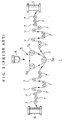
- the wire saw apparatus 1 comprises a wire supply spool 3 for supplying a cutting wire 2, a cutting head 5 for cutting a work 4 by using the cutting wire 2, and a wire take-up spool 6 for taking-up the cutting wire 2.
- the cutting head 5 comprises three main rollers 5a, 5b, and 5c.
- the work 4 is sawed or cut by pushing the work 4 against a plurality of lines of cutting wire 2 which is wrapped around the main rollers 5a, 5b, and 5c of the cutting head 5 in a spiral configuration, and by supplying an abrasive slurry containing abrasive grains into between the work 4 and the lines of cutting wire 2, while complex action of the cutting wire 2 which comprises back and forth action in the direction of the lines and feeding action, is taken.
- the wrapping angle of portions of the cutting wire 2, which is wrapped around a guide roller 7 and are in contact with the guide rollers 7, is only about 180° at the most. Because of such a small wrapping angle of the cutting wire 2, the wire 2 is apt to become loose while cutting the work 4. As a result, a stress concentration is apt to occur in a portion of the wire 2, so that a breakage of the wire 2 occurs. When such a breakage of the wire occurs, work for threading the cutting wire 2 again is required. There is a problem that such work for re-threading of the wire is laborious and requires a long time.
- Each guide roller 7 has a groove 9 having a V-shaped section, which may be hereinafter simply referred to a V-shaped groove, on the peripheral surface thereof, as shown in FIG. 6. Therefore, the cutting wire 2 in the groove 9 is seated on the bottom of the groove 9 when some tension is applied to the wire 2. However, when the cutting wire 2 comes loose, the wire 2 rolls and moves in the V-shaped groove 9, so that partial wear is produced on the wall surface of the groove. When such partial wear is produced, replacement of the guide roller 7 is required. Because the replacement work includes work for re-threading the cutting wire 2 again and the like, there is a problem that the work is laborious and requires a long time.
- Some known wire saw apparatuses adopt guide rollers 7a or 7b each of which has one or more spare peripheral grooves 9a with a V-shaped section, as shown in FIGS. 7 and 8.
- Such a type of wire saw apparatus having such guide rollers 7a or 7b with spare peripheral grooves 9a has the disadvantages of requiring higher manufacturing costs and of being large-sized.
- a wire saw apparatus comprising:
- Such a wire saw apparatus has rolls with a long lift and is less susceptible to loosening of the wire and to breakage of it.
- the peripheral square-shaped groove has a width of 2-20 times the diameter of the wire.
- the wire is wrapped around the roller in the peripheral groove with a square-shaped section, and the number of turns of the wrapped wire in the peripheral square-shaped groove is preferably not less than 1 and not more than 5.
- the width of the groove with a square-shaped section may be in the range of 0.3-5 mm.
- the cutting wire is hard to come loose while cutting a work by the wire and a stress concentration is hard to occur in a portion of the wire. Consequently, a breakage of the cutting wire is hard to happen.
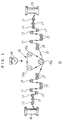
- FIG. 1 shows a wire saw apparatus according to an embodiment of the present invention.
- the wire saw apparatus 10 comprises a wire supply spool (wire supply member) 13 for supplying a cutting wire 12, a cutting head 15 for cutting a work 14 by using the cutting wire 12, and a wire take-up spool (wire take-up member) 16 for taking-up the cutting wire 12.
- a plurality of guide rollers 17, 17, ... for guiding the cutting wire 12 and for giving a predetermined tension to the cutting wire 12 are arranged between the wire supply spool 13 and the cutting head 15 and between the cutting head 15 and the wire take-up spool 16.
- the cutting head 15 comprises three main rollers 15a, 15b, and 15c.
- the work 14 is cut by pushing the work 14 against a plurality of lines of the cutting wire 12 which are wrapped around the main rollers 15a, 15b, and 15c of the cutting head 15 in a spiral configuration, and by supplying an abrasive slurry containing abrasive grains into between the work 14 and the lines of the cutting wire 12, while complex action of the cutting wire 12 which comprises back and forth action in the direction of the line and feeding action, is taken.
- the three main rollers 15a, 15b, and 15c which form the cutting head 15, and the plurality of guide rollers 17, 17, ... have structures as follows.
- FIG. 2 shows a portion of the main roller 15a.
- the main roller 15a has a large number of grooves 20 each having a V-shaped section, at regular intervals on the peripheral surface thereof, shown in FIG. 2.
- Each V-shaped groove 20 accepts one of the plurality of lines of cutting wire 12 and to maintain the plurality of lines of cutting wire in a fixed and parallel configuration.
- the groove in which the wire 12 is wrapped at first is the groove 21 having a square-shaped section, as shown in FIG. 3.
- the square-shaped groove 21 has a width of 2-20 times the diameter of the cutting wire 12, and the wire is wrapped around the roller in the groove with some turns which are not less than 1 turn and not more than 5 turns. Since the diameter of the cutting wire 12 is generally in the range of 0.14-0.20 mm, a width of 0.3-5 mm is enough for the square-shaped groove 21, in consideration of gaps between wrapped lines of cutting wire 12. The reason for the number of turns of cutting wire 12 in the square-shaped groove being not more than 5 is that turns more than 5 not only cannot be expected to give larger effects but also make the wrapping work laborious and requires a large-sized main roller 15a.
- FIG. 4 shows a guide roller 17.
- the guide roller 17 also has a groove 22 having a square-shaped section on the peripheral surface thereof.
- the square-shaped groove 22 has a width not less than double the diameter of the cutting wire 12, and the wire is wrapped around the roller in the groove 22 with some turns which are not less than 1 turn and not more than 5 turns.
- the width of the square-shaped groove 22 is similar to that of the groove of the main roller 15a.
- the wire saw apparatus 10 shown in FIG. 1 is provided with a main roller 15a and guide rollers 17, around which the lines of cutting wire 12 are wrapped in the above-described manner.
- the lower main roller 15a and the guide rollers 17 which are illustrated by triple concentric circles are the rollers around which the cutting wire 12 is wrapped in the square-shaped groove with some turns which are not less than 1 turn and not more than 5 turns.
- the function and effects of the wire saw apparatus 10 having such a structure will be explained. Because the cutting wire is wrapped around the main roller 15a in the square-shaped groove 21 and around the guide rollers 17 in the square-shaped groove 22, with some turns which are not less than one turn, the wire 12 is hard to come loose and a stress concentration is hard to occur in a portion of the wire 12, so that a breakage of cutting wire 12 is hard to happen. Consequently, it is possible to extremely reduce works for stretching the cutting wire 12 again due to breakage of the wire 12 and to effectively carry out a cutting operation for the work 14.
- each guide roller 17 has the peripheral square-shaped groove 22 and the side walls in the groove 22 is approximately perpendicular to the bottom surface, even if the cutting wire 12 comes somewhat loose, it is possible to prevent partial wear on the side wall in the groove and consequently to extend the life of the guide roller 17. Therefore, it is possible to reduce works for stretching the cutting wire 12 again due to exchange of the guide roller 17 and to effectively carry out a cutting operation for the work 14.
- a peripheral square-shaped groove 21 is formed in also the lower main roller 15a.
- a groove 21 with a square-shaped section may be not formed in the main roller 15a because the effects of the present invention can be obtained by only the guide rollers each having a peripheral square-shaped groove 22. It is a matter of course that if a peripheral square-shaped groove 21 is formed in also the lower main roller 15a, the cutting wire 12 is hard to come loose furthermore.
Landscapes
- Engineering & Computer Science (AREA)
- Mechanical Engineering (AREA)
- Processing Of Stones Or Stones Resemblance Materials (AREA)
- Finish Polishing, Edge Sharpening, And Grinding By Specific Grinding Devices (AREA)
Claims (7)
- Drahtsägevorrichtung, die umfaßt:ein Drahtzuführelement (13),einen Schneidkopf (15) mit einer Vielzahl von Hauptrollen (15a, b, c), um die ein Draht (12) von dem Drahtzuführelement (13) läuft,ein Drahtaufwickelelement (16), das den Draht (12) von dem Schneidkopf (15) aufwickelt, undeine Vielzahl von Führungsrollen (17), die den Draht (12) führen und zwischen dem Drahtzuführelement (13) und dem Schneidkopf (15) sowie zwischen dem Schneidkopf (15) und dem Drahtaufwickelelement (16) angeordnet sind,
dadurch gekennzeichnet, daß wenigstens eine Rolle der Hauptrollen (15, a, b, c) und der Führungsrollen (17) eine Nut (21, 22) mit einem rechteckigen Querschnitt an ihrer Umfangsfläche hat. - Drahtsägevorrichtung nach Anspruch 1, wobei jede der Führungsrollen (17) eine Umfangsnut (22) mit einem rechteckigen Querschnitt an ihrer Umfangsfläche hat.
- Drahtsägevorrichtung nach Anspruch 1 oder 2, wobei lediglich eine (15a) der Hauptrollen, um die der Draht (12) von den Drahtzuführelementen (13) zuerst läuft, eine Nut (21) mit einem rechteckigen Querschnitt hat.
- Drahtsägevorrichtung nach Anspruch 3, wobei der Draht (12) zunächst um die Nut (21) mit einem rechteckigen Querschnitt an der Hauptrolle (15a) herum läuft.
- Drahtsägevorrichtung nach einem der vorangehenden Ansprüche, wobei die bzw. jede Nut (21, 22) mit einem rechteckigen Querschnitt eine Breite vom 2- bis zum 20-fachen des Durchmessers des Drahtes (12) hat.
- Drahtsägevorrichtung nach einem der vorangehenden Ansprüche, wobei der Draht (12) um die bzw. jede Rolle (15, 17) in der Nut (21, 22) mit einem rechteckigen Querschnitt herumläuft und die Anzahl von Wicklungen des herumlaufenden Drahtes (12) in der bzw. jeder Nut (21, 22) mit einem rechteckigen Querschnitt nicht weniger als 1 und nicht mehr als 5 beträgt.
- Drahtsägevorrichtung nach einem der vorangehenden Ansprüche, wobei die Breite der bzw. jeder Nut (21, 22) mit einem rechteckigen Querschnitt in einem Bereich von 0,3 bis 5 mm liegt.
Applications Claiming Priority (2)
| Application Number | Priority Date | Filing Date | Title |
|---|---|---|---|
| JP6197426A JP2755909B2 (ja) | 1994-07-29 | 1994-07-29 | ワイヤソー |
| JP197426/94 | 1994-07-29 |
Publications (2)
| Publication Number | Publication Date |
|---|---|
| EP0694366A1 EP0694366A1 (de) | 1996-01-31 |
| EP0694366B1 true EP0694366B1 (de) | 1998-09-16 |
Family
ID=16374329
Family Applications (1)
| Application Number | Title | Priority Date | Filing Date |
|---|---|---|---|
| EP95305114A Expired - Lifetime EP0694366B1 (de) | 1994-07-29 | 1995-07-21 | Drahtsägevorrichtung |
Country Status (4)
| Country | Link |
|---|---|
| US (1) | US5907988A (de) |
| EP (1) | EP0694366B1 (de) |
| JP (1) | JP2755909B2 (de) |
| DE (1) | DE69504781T2 (de) |
Families Citing this family (17)
| Publication number | Priority date | Publication date | Assignee | Title |
|---|---|---|---|---|
| JPH1110509A (ja) * | 1997-06-24 | 1999-01-19 | Nippei Toyama Corp | ワイヤソーの張力付与機構 |
| CH692485A5 (fr) * | 1998-02-13 | 2002-07-15 | Hct Shaping Systems Sa | Dispositif de sciage par fil. |
| JP4049900B2 (ja) * | 1998-08-20 | 2008-02-20 | 株式会社スーパーシリコン研究所 | ワイヤソー切断装置 |
| TW383249B (en) * | 1998-09-01 | 2000-03-01 | Sumitomo Spec Metals | Cutting method for rare earth alloy by annular saw and manufacturing for rare earth alloy board |
| MY126994A (en) | 1999-12-14 | 2006-11-30 | Hitachi Metals Ltd | Method and apparatus for cutting a rare earth alloy |
| JP4397320B2 (ja) * | 2003-11-13 | 2010-01-13 | 日本碍子株式会社 | ワイヤーソー加工装置、及びワイヤーソー加工方法 |
| US20080104848A1 (en) * | 2006-11-07 | 2008-05-08 | Cooke Brian S | Reciprocating pipe cutter |
| DE102007016334B4 (de) * | 2007-04-04 | 2011-04-21 | Siemens Ag | Drahtsäge und Verfahren zur Herstellung einer Drahtsäge |
| ITTO20080385A1 (it) * | 2008-05-22 | 2009-11-23 | Co Fi Plast Srl | Segatrice a piu' utensili a filo per il taglio di materiale in blocchi |
| JP5064583B1 (ja) * | 2011-04-13 | 2012-10-31 | コマツNtc株式会社 | ワイヤソー |
| CN102328354A (zh) * | 2011-06-20 | 2012-01-25 | 镇江市港南电子有限公司 | 一种用于硅片切割的导轮 |
| FR2988023A1 (fr) * | 2012-03-16 | 2013-09-20 | Sodetal Sas | Fil a scier, methode de fabrication d'un tel fil et utilisation |
| CN105142836A (zh) | 2013-05-17 | 2015-12-09 | 梅耶博格公司 | 包括有槽滑轮的线锯 |
| CN103395130B (zh) * | 2013-07-25 | 2015-08-19 | 曹爱苗 | 一种完全平面式布线的金刚石线切割机 |
| CN103600426A (zh) * | 2013-10-22 | 2014-02-26 | 无锡上机数控股份有限公司 | 一种数控金刚线线锯切片机 |
| CN105252660B (zh) * | 2015-11-22 | 2017-03-22 | 天津英利新能源有限公司 | 一种硅片切割处理方法 |
| CN116890290B (zh) * | 2022-12-30 | 2026-01-02 | 桂林磨院材料科技有限公司 | 一种电镀金刚石分段错位式多边形线锯及其加工方法 |
Family Cites Families (9)
| Publication number | Priority date | Publication date | Assignee | Title |
|---|---|---|---|---|
| US2702538A (en) * | 1950-08-10 | 1955-02-22 | Burkhardt Otto Wilhelm | Chain saw for stone working |
| US3841297A (en) * | 1971-12-01 | 1974-10-15 | Motorola Inc | Machine for cutting brittle materials |
| GB1415240A (en) * | 1973-11-27 | 1975-11-26 | Motorola Inc | Machine for cutting brittle materials |
| JPS61293766A (ja) * | 1985-06-21 | 1986-12-24 | Hitachi Ltd | ワイヤ−ソによる微細加工法 |
| JPH0635107B2 (ja) * | 1987-12-26 | 1994-05-11 | 株式会社タカトリハイテック | ワイヤソー |
| JPH01234153A (ja) * | 1988-03-11 | 1989-09-19 | Osaka Titanium Co Ltd | ワイヤソーマシン |
| JPH01316163A (ja) * | 1988-06-13 | 1989-12-21 | Osaka Titanium Co Ltd | ワイヤソーマシン用補助ローラ |
| JPH03126554U (de) * | 1990-04-04 | 1991-12-19 | ||
| AT398935B (de) * | 1992-10-21 | 1995-02-27 | Swarovski Tyrolit Schleif | Sägeseildrehvorrichtung |
-
1994
- 1994-07-29 JP JP6197426A patent/JP2755909B2/ja not_active Expired - Lifetime
-
1995
- 1995-07-21 DE DE69504781T patent/DE69504781T2/de not_active Expired - Fee Related
- 1995-07-21 EP EP95305114A patent/EP0694366B1/de not_active Expired - Lifetime
-
1997
- 1997-07-31 US US08/903,759 patent/US5907988A/en not_active Expired - Fee Related
Also Published As
| Publication number | Publication date |
|---|---|
| EP0694366A1 (de) | 1996-01-31 |
| US5907988A (en) | 1999-06-01 |
| JPH0839418A (ja) | 1996-02-13 |
| DE69504781D1 (de) | 1998-10-22 |
| DE69504781T2 (de) | 1999-03-11 |
| JP2755909B2 (ja) | 1998-05-25 |
Similar Documents
| Publication | Publication Date | Title |
|---|---|---|
| EP0694366B1 (de) | Drahtsägevorrichtung | |
| EP0745447B1 (de) | Drahtsägevorrichtung | |
| JP3427956B2 (ja) | ワイヤーソー装置 | |
| JP3047178B2 (ja) | ワイヤソー、及び成形品を切断するための方法 | |
| KR20000018649A (ko) | 세그먼트 타입의 다이아몬드 소우 브레이드 | |
| US20150283727A1 (en) | Method for slicing wafers from a workpiece using a sawing wire | |
| TWI692394B (zh) | 線鋸裝置 | |
| JP2011526215A (ja) | ワイヤーソー切断装置 | |
| KR970069280A (ko) | 와이어톱 및 가공물 저밈 방법 | |
| JP2017213627A (ja) | ワークの切断方法 | |
| KR19980024142A (ko) | 멀티와이어 톱 | |
| JP2000309015A (ja) | ワイヤソーのワイヤ巻掛方法 | |
| EP2647458A1 (de) | Draht für Halbleiterdrahtsäge und Drahtsäge | |
| JP2005014157A (ja) | マルチワイヤソー | |
| KR102880759B1 (ko) | 공작물로부터 복수의 디스크를 동시에 분리하기 위한 방법 및 장치 | |
| KR101290213B1 (ko) | 와이어 소 | |
| JPH1044142A (ja) | マルチワイヤーソー | |
| JPH11123648A (ja) | ワイヤーソー用多溝ローラ | |
| JP3658920B2 (ja) | 半導体インゴットのスライス装置 | |
| JP2503831B2 (ja) | エンドレス歯付ベルト | |
| JPS61121819A (ja) | ワイヤ−ソ−用ワイヤ− | |
| JP3873490B2 (ja) | マルチワイヤソー装置 | |
| KR102644660B1 (ko) | 와이어소 장치의 제조방법 및 와이어소 장치 | |
| JP2001018157A (ja) | ワイヤーソー | |
| JP3396291B2 (ja) | ワイヤソー及びワイヤソー切断方法 |
Legal Events
| Date | Code | Title | Description |
|---|---|---|---|
| PUAI | Public reference made under article 153(3) epc to a published international application that has entered the european phase |
Free format text: ORIGINAL CODE: 0009012 |
|
| AK | Designated contracting states |
Kind code of ref document: A1 Designated state(s): DE FR GB |
|
| 17P | Request for examination filed |
Effective date: 19960712 |
|
| GRAG | Despatch of communication of intention to grant |
Free format text: ORIGINAL CODE: EPIDOS AGRA |
|
| 17Q | First examination report despatched |
Effective date: 19971017 |
|
| GRAG | Despatch of communication of intention to grant |
Free format text: ORIGINAL CODE: EPIDOS AGRA |
|
| GRAH | Despatch of communication of intention to grant a patent |
Free format text: ORIGINAL CODE: EPIDOS IGRA |
|
| GRAH | Despatch of communication of intention to grant a patent |
Free format text: ORIGINAL CODE: EPIDOS IGRA |
|
| GRAA | (expected) grant |
Free format text: ORIGINAL CODE: 0009210 |
|
| AK | Designated contracting states |
Kind code of ref document: B1 Designated state(s): DE FR GB |
|
| REF | Corresponds to: |
Ref document number: 69504781 Country of ref document: DE Date of ref document: 19981022 |
|
| ET | Fr: translation filed | ||
| PGFP | Annual fee paid to national office [announced via postgrant information from national office to epo] |
Ref country code: FR Payment date: 19990709 Year of fee payment: 5 |
|
| PGFP | Annual fee paid to national office [announced via postgrant information from national office to epo] |
Ref country code: GB Payment date: 19990721 Year of fee payment: 5 |
|
| PGFP | Annual fee paid to national office [announced via postgrant information from national office to epo] |
Ref country code: DE Payment date: 19990723 Year of fee payment: 5 |
|
| PLBE | No opposition filed within time limit |
Free format text: ORIGINAL CODE: 0009261 |
|
| STAA | Information on the status of an ep patent application or granted ep patent |
Free format text: STATUS: NO OPPOSITION FILED WITHIN TIME LIMIT |
|
| 26N | No opposition filed | ||
| PG25 | Lapsed in a contracting state [announced via postgrant information from national office to epo] |
Ref country code: GB Free format text: LAPSE BECAUSE OF NON-PAYMENT OF DUE FEES Effective date: 20000721 |
|
| GBPC | Gb: european patent ceased through non-payment of renewal fee |
Effective date: 20000721 |
|
| PG25 | Lapsed in a contracting state [announced via postgrant information from national office to epo] |
Ref country code: FR Free format text: LAPSE BECAUSE OF NON-PAYMENT OF DUE FEES Effective date: 20010330 |
|
| REG | Reference to a national code |
Ref country code: FR Ref legal event code: ST |
|
| PG25 | Lapsed in a contracting state [announced via postgrant information from national office to epo] |
Ref country code: DE Free format text: LAPSE BECAUSE OF NON-PAYMENT OF DUE FEES Effective date: 20010501 |