EP0693997B1 - Doppelt wirkendes bremsventil - Google Patents
Doppelt wirkendes bremsventil Download PDFInfo
- Publication number
- EP0693997B1 EP0693997B1 EP94914391A EP94914391A EP0693997B1 EP 0693997 B1 EP0693997 B1 EP 0693997B1 EP 94914391 A EP94914391 A EP 94914391A EP 94914391 A EP94914391 A EP 94914391A EP 0693997 B1 EP0693997 B1 EP 0693997B1
- Authority
- EP
- European Patent Office
- Prior art keywords
- pressure
- hydraulic
- gear
- brake valve
- pressure relief
- Prior art date
- Legal status (The legal status is an assumption and is not a legal conclusion. Google has not performed a legal analysis and makes no representation as to the accuracy of the status listed.)
- Expired - Lifetime
Links
Images

Classifications
-
- F—MECHANICAL ENGINEERING; LIGHTING; HEATING; WEAPONS; BLASTING
- F16—ENGINEERING ELEMENTS AND UNITS; GENERAL MEASURES FOR PRODUCING AND MAINTAINING EFFECTIVE FUNCTIONING OF MACHINES OR INSTALLATIONS; THERMAL INSULATION IN GENERAL
- F16H—GEARING
- F16H61/00—Control functions within control units of change-speed- or reversing-gearings for conveying rotary motion ; Control of exclusively fluid gearing, friction gearing, gearings with endless flexible members or other particular types of gearing
- F16H61/38—Control of exclusively fluid gearing
- F16H61/40—Control of exclusively fluid gearing hydrostatic
- F16H61/46—Automatic regulation in accordance with output requirements
- F16H61/461—Automatic regulation in accordance with output requirements not involving a variation of the output capacity of the main pumps or motors
-
- B—PERFORMING OPERATIONS; TRANSPORTING
- B60—VEHICLES IN GENERAL
- B60T—VEHICLE BRAKE CONTROL SYSTEMS OR PARTS THEREOF; BRAKE CONTROL SYSTEMS OR PARTS THEREOF, IN GENERAL; ARRANGEMENT OF BRAKING ELEMENTS ON VEHICLES IN GENERAL; PORTABLE DEVICES FOR PREVENTING UNWANTED MOVEMENT OF VEHICLES; VEHICLE MODIFICATIONS TO FACILITATE COOLING OF BRAKES
- B60T1/00—Arrangements of braking elements, i.e. of those parts where braking effect occurs specially for vehicles
- B60T1/02—Arrangements of braking elements, i.e. of those parts where braking effect occurs specially for vehicles acting by retarding wheels
- B60T1/08—Arrangements of braking elements, i.e. of those parts where braking effect occurs specially for vehicles acting by retarding wheels using fluid or powdered medium
-
- B—PERFORMING OPERATIONS; TRANSPORTING
- B60—VEHICLES IN GENERAL
- B60W—CONJOINT CONTROL OF VEHICLE SUB-UNITS OF DIFFERENT TYPE OR DIFFERENT FUNCTION; CONTROL SYSTEMS SPECIALLY ADAPTED FOR HYBRID VEHICLES; ROAD VEHICLE DRIVE CONTROL SYSTEMS FOR PURPOSES NOT RELATED TO THE CONTROL OF A PARTICULAR SUB-UNIT
- B60W10/00—Conjoint control of vehicle sub-units of different type or different function
- B60W10/10—Conjoint control of vehicle sub-units of different type or different function including control of change-speed gearings
-
- B—PERFORMING OPERATIONS; TRANSPORTING
- B60—VEHICLES IN GENERAL
- B60W—CONJOINT CONTROL OF VEHICLE SUB-UNITS OF DIFFERENT TYPE OR DIFFERENT FUNCTION; CONTROL SYSTEMS SPECIALLY ADAPTED FOR HYBRID VEHICLES; ROAD VEHICLE DRIVE CONTROL SYSTEMS FOR PURPOSES NOT RELATED TO THE CONTROL OF A PARTICULAR SUB-UNIT
- B60W10/00—Conjoint control of vehicle sub-units of different type or different function
- B60W10/18—Conjoint control of vehicle sub-units of different type or different function including control of braking systems
-
- F—MECHANICAL ENGINEERING; LIGHTING; HEATING; WEAPONS; BLASTING
- F16—ENGINEERING ELEMENTS AND UNITS; GENERAL MEASURES FOR PRODUCING AND MAINTAINING EFFECTIVE FUNCTIONING OF MACHINES OR INSTALLATIONS; THERMAL INSULATION IN GENERAL
- F16H—GEARING
- F16H61/00—Control functions within control units of change-speed- or reversing-gearings for conveying rotary motion ; Control of exclusively fluid gearing, friction gearing, gearings with endless flexible members or other particular types of gearing
- F16H61/38—Control of exclusively fluid gearing
- F16H61/40—Control of exclusively fluid gearing hydrostatic
- F16H61/4157—Control of braking, e.g. preventing pump over-speeding when motor acts as a pump
-
- F—MECHANICAL ENGINEERING; LIGHTING; HEATING; WEAPONS; BLASTING
- F16—ENGINEERING ELEMENTS AND UNITS; GENERAL MEASURES FOR PRODUCING AND MAINTAINING EFFECTIVE FUNCTIONING OF MACHINES OR INSTALLATIONS; THERMAL INSULATION IN GENERAL
- F16H—GEARING
- F16H61/00—Control functions within control units of change-speed- or reversing-gearings for conveying rotary motion ; Control of exclusively fluid gearing, friction gearing, gearings with endless flexible members or other particular types of gearing
- F16H61/38—Control of exclusively fluid gearing
- F16H61/40—Control of exclusively fluid gearing hydrostatic
- F16H61/42—Control of exclusively fluid gearing hydrostatic involving adjustment of a pump or motor with adjustable output or capacity
- F16H61/423—Motor capacity control by fluid pressure control means
-
- F—MECHANICAL ENGINEERING; LIGHTING; HEATING; WEAPONS; BLASTING
- F16—ENGINEERING ELEMENTS AND UNITS; GENERAL MEASURES FOR PRODUCING AND MAINTAINING EFFECTIVE FUNCTIONING OF MACHINES OR INSTALLATIONS; THERMAL INSULATION IN GENERAL
- F16H—GEARING
- F16H59/00—Control inputs to control units of change-speed- or reversing-gearings for conveying rotary motion
- F16H59/68—Inputs being a function of gearing status
- F16H59/70—Inputs being a function of gearing status dependent on the ratio established
Definitions
- the invention relates to a double-acting brake valve which is connected to a hydrostatic-mechanical transmission unit via hydraulic lines.
- the hydrostatic-mechanical transmission unit preferably consists of an adjustable hydraulic motor and a downstream mechanical manual transmission, in particular a two-speed transmission.
- the brake valve is kept open during driving by the pressure in one of the connecting lines, and in braking mode, the hydraulic fluid is throttled out via a throttle or a pressure relief valve in the case of short-circuited hydraulic lines.
- a generic hydrostatic drive for vehicles has become known from EP-B-0 428 581 (application WO-A-90/01429).
- the hydraulic motor is arranged in the hub of a drive wheel.
- Driving brake valves are provided which are arranged in pressure lines and which open or close the return flow cross section as a function of the operating pressure of the hydraulic motor.
- the present invention has for its object to provide a brake valve with which, depending on which gear of a downstream transmission is shifted, different delays can be achieved.
- the pressure relief valves are designed as two-stage valves which are switched depending on the gear by the pressure in the hydraulic lines and a pilot pressure. Due to the two pressure levels and the level of the prevailing pilot pressure, the braking capacity of the hydraulic motor can be matched to the gear ratio step between gear stages two and one of a downstream transmission. Dangerous or at least uncomfortable driving situations are thus safely eliminated.
- a simple hydraulic construction is obtained if the hydraulic lines can be connected to each other via a pressure relief valve and a connecting line.
- a pressure line is connected to the pressure line of the transmission for shifting a particular gear, in particular the first gear.
- the directional control valve connects to the pressure relief valves only in braking mode and in connection with the shifted first gear of the manual transmission.
- Two hydraulic lines 4 and 5 lead from the brake valve 1 to an adjustable hydraulic motor 6.
- the hydraulic motor 6 is connected to a mechanical manual transmission 7. In the present case, it is the drive of an excavator, the manual transmission 7 is designed as a two-speed transmission.
- the hydraulic motor 6 and the manual transmission 7 form a hydrostatic-mechanical transmission unit.
- a third hydraulic line 8 leads from the brake valve 1 to an adjustment unit 9 for the hydraulic motor 6.
- a brake piston 10 When driving, a brake piston 10 is opened by the pressure in one of the hydraulic lines 2 or 3, so that the hydraulic fluid can flow freely through the hydraulic line 2 into the hydraulic line 4 or from the hydraulic line 3 into the hydraulic line 5 and thus to the hydraulic motor 6 .
- the brake piston 10 In braking operation, the brake piston 10 is transferred to the center position shown in one of the hydraulic lines 2 or 3 because of the missing inlet pressure.
- the hydraulic motor 6 becomes a pump because of the inert vehicle mass.
- the hydraulic motor 6 then conveys hydraulic fluid either via the hydraulic line 4 or the hydraulic line 5 to the brake piston 10.
- the hydraulic fluid runs out of the hydraulic line 4 into the hydraulic line 2 or out of the hydraulic line 5 into the hydraulic line 3 via a throttle point 11 or 12, which are connected in parallel to check valves. Depending on how large the backflow of the hydraulic fluid in line 4 or 5, a more or less high pressure is established in one of these lines.
- the hydraulic lines 4 and 5 can be short-circuited via a connecting line 13.
- this connecting line 13 there are two identical pressure relief valves 14. If a pressure is established in the hydraulic line 4 or in the hydraulic line 5 that is equal to the opening pressure of the pressure relief valves 14, the respectively controlled pressure relief valve 14 opens the connection between the hydraulic lines 4 and 5 or 5 and 4.
- the braking torque of the hydraulic motor results from the swallowing volume and the pressure (brake pressure) prevailing in the hydraulic line 4 or 5.
- braking torques of different sizes are set at the transmission output in the braking state.
- the braking torques of different sizes depend on the step change in the gear ratio. It follows that the vehicle is decelerated slightly in second gear. In the first gear, however, the delay is greater by the factor of the translation jump. This can lead to dangerous driving conditions. For example, the vehicle can become uncontrollable due to slipping wheels. At least the driver's first gear delays are very uncomfortable. This disadvantage is eliminated with the solution according to the invention.
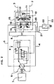
- FIG. 2 shows a hydraulic diagram with a two-stage, double-acting brake valve 15.
- the two-stage, double-acting brake valve 15 is characterized in particular by the fact that pressure relief valves 16 are used which operate in two stages.
- the hydraulic lines 4 and 5 are each connected to a pressure relief valve 16.
- the hydraulic line 4 and the hydraulic line 5 are connected to the brake piston 10.
- the hydraulic lines 4 and 5 can be short-circuited via a connecting line 17. In this connecting line 17 there are two identical pressure relief valves 16.
- a connection line 21 leads to the pressure relief valves 16 and branches off from a 3/2-way valve 22. To This 3/2-way valve is guided by a pressure line 23. This pressure line 23 is connected to the pressure line of the manual transmission 7 for shifting the first gear.
- the directional control valve 22 only releases the connection from the pressure line 23 to the connecting line 21 when there is no pressure in the hydraulic line 8. In this case, the pressure line 21 is connected to the tank via the 3/2-way valve and is therefore depressurized.
- the function of the two-stage, double-acting brake valve 15 is as follows:
- a first pressure stage is effective which corresponds to a first opening pressure of the pressure relief valves 16.
- a second pressure stage is effective when the second stage of the pressure relief valves 16 is switched by the pilot pressure prevailing in the connecting line 21. It should be noted that the second pressure level is below the pressure level of the first pressure level.
- the difference between the two pressure stages results from the geometric relationships within the pressure relief valves and from the level of the pilot pressure which is present at the pressure relief valves 16. Due to the two pressure levels and the level of the prevailing pilot pressure, the braking capacity of the hydraulic motor can be matched as desired to the step change in gear ratio between gear stages 2 and 1 of the downstream manual transmission 7.
- the 3/2-way valve 22 ensures that the second pressure stage of the pressure relief valves 16 is effective only in braking mode, ie rolling out of the vehicle, in connection with the shifted first gear of the manual transmission. This also has the advantage that the same torque of the hydraulic motor is available for both gears of the manual transmission 7 (corresponding to the pressure prevailing in the hydraulic lines 4 and 5, respectively).
Landscapes
- Engineering & Computer Science (AREA)
- General Engineering & Computer Science (AREA)
- Mechanical Engineering (AREA)
- Transportation (AREA)
- Chemical & Material Sciences (AREA)
- Combustion & Propulsion (AREA)
- Physics & Mathematics (AREA)
- Fluid Mechanics (AREA)
- Control Of Transmission Device (AREA)
- Control Of Fluid Gearings (AREA)
- Braking Systems And Boosters (AREA)
- Control Of Driving Devices And Active Controlling Of Vehicle (AREA)
- Fluid-Pressure Circuits (AREA)
Abstract
Description
- Die Erfindung bezieht sich auf ein doppelt wirkendes Bremsventil, das über Hydraulikleitungen mit einer hydrostatisch-mechanischen Getriebeeinheit verbunden ist. Die hydrostatisch-mechanische Getriebeeinheit besteht vorzugsweise aus einem verstellbaren Hydraulikmotor und einem nachgeschalteten mechanischen Schaltgetriebe, insbesondere einem Zwei-Gang-Getriebe. Das Bremsventil wird im Fahrbetrieb durch den Druck in einer der Anschlußleitungen offengehalten und im Bremsbetrieb erfolgt ein gedrosselter Ablauf der Hydraulikflüssigkeit über jeweils eine Drossel oder jeweils ein Druckbegrenzungsventil bei kurzgeschlossenen Hydraulikleitungen.
- Aus der EP-B-0 428 581 (Anmeldung WO-A-90/01429) ist ein gattungsbildender hydrostatischer Antrieb für Fahrzeuge bekannt geworden. Bei diesem Fahrzeug ist der Hydraulikmotor in der Nabe eines Antriebsrades angeordnet. Es sind Fahrbremsventile vorgesehen, die in Druckleitungen angeordnet sind und in Abhängigkeit vom Betriebsdruck des Hydromotors den Rückflußquerschnitt auf- bzw. zusteuern.
- Bei den bekannten doppelt wirkenden Bremsventilen ist nachteilig, daß das Bremsvermögen des Hydraulikmotors beim Ausrollen nicht auf den Übersetzungssprung zwischen den Gangstufen eines nachgeschalteten Schaltgetriebes abgestimmt werden kann. Somit ist die Verzögerung gangabhängig. Eine große Verzögerung, insbesondere im ersten Gang, wird vom Fahrer als sehr unangenehm empfunden.
- Der vorliegenden Erfindung liegt die Aufgabe zugrunde, ein Bremsventil zu schaffen, mit dem, je nachdem, welcher Gang eines nachgeschalteten Schaltgetriebes geschaltet ist, unterschiedliche Verzögerungen erzielbar sind.
- Die gestellte Aufgabe wird dadurch gelöst, daß die Druckbegrenzungsventile als zweistufige Ventile ausgebildet sind, die durch den Druck in den Hydraulikleitungen und einen Pilotdruck gangabhängig geschaltet werden. Durch die beiden Druckstufen und die Höhe des herrschenden Pilotdruckes kann das Bremsvermögen des Hydraulikmotors auf den Übersetzungssprung zwischen den Gangstufen zwei und eins eines nachgeschalteten Getriebes beliebig abgestimmt werden. Gefährliche oder zumindest unangenehme Fahrsituationen werden dadurch mit Sicherheit ausgeschaltet.
- Einen einfachen hydraulischen Aufbau erhält man, wenn die Hydraulikleitungen über jeweils ein Druckbegrenzungsventil und je eine Verbindungsleitung miteinander verbindbar sind.
- Um einen Pilotdruck gangabhängig den Druckbegrenzungsventilen aufzuschalten, ist es vorteilhaft, eine Druckleitung über ein Wegeventil und eine Anschlußleitung zu den Druckbegrenzungsventilen zu führen. Die Druckleitung ist hierbei mit der Druckleitung des Getriebes zum Schalten eines bestimmten Ganges, insbesondere des ersten Ganges, verbunden.
- Über das Wegeventil besteht eine Verbindung zu den Druckbegrenzungsventilen ausschließlich im Bremsbetrieb und in Verbindung mit dem geschalteten ersten Gang des Schaltgetriebes.
- Weitere vorteilhafte Merkmale sind den Unteransprüchen 5 bis 8 zu entnehmen.
- Weitere, für die Erfindung wesentliche Merkmale sowie die daraus resultierenden Vorteile sind der nachfolgenden Beschreibung eines Ausführungsbeispiels der Erfindung zu entnehmen.
Es zeigen: - Fig. 1
- ein Hydraulikschema mit einem doppelt wirkenden Bremsventil nach dem Stand der Technik und
- Fig. 2
- ein Hydraulikschema nach der Erfindung mit zweistufigen, doppelt wirkenden Bremsventilen.
- Der Verständlichkeit wegen wird im folgenden die Verwendung eines doppelt wirkenden Fahrbremsventils 1 innerhalb eines Hydraulikschemas nach dem Stand der Technik erläutert. An das Gehäuse (mit strichpunktierten Linien dargestellt) sind zwei Hydraulikleitungen 2 und 3 herangeführt. Die Hydraulikleitungen 2 und 3 verbinden ein selbst nicht dargestelltes Wegeventil mit dem Bremsventil 1. Je nach Schaltstellung dieses Wegeventils ist entweder die Hydraulikleitung 2 oder die Hydraulikleitung 3 der Zulauf für Hydraulikflüssigkeit oder die Hydraulikflüssigkeit läuft über eine dieser Hydraulikleitungen 2 oder 3, vom Bremsventil 1 kommend, zurück.
- Vom Bremsventil 1 führen zwei Hydraulikleitungen 4 und 5 zu einem verstellbaren Hydraulikmotor 6. Der Hydraulikmotor 6 ist mit einem mechanischen Schaltgetriebe 7 verbunden. Im vorliegenden Fall, es handelt sich um den Antrieb eines Baggers, ist das Schaltgetriebe 7 als Zwei-Gang-Getriebe ausgebildet. Der Hydraulikmotor 6 und das Schaltgetriebe 7 bilden eine hydrostatisch-mechanische Getriebeeinheit.
- Eine dritte Hydraulikleitung 8 führt vom Bremsventil 1 zu einer Verstelleinheit 9 für den Hydraulikmotor 6.
- Im Fahrbetrieb wird ein Bremskolben 10 durch den Druck in einer der Hydraulikleitungen 2 oder 3 geöffnet, so daß die Hydraulikflüssigkeit im freien Durchfluß von der Hydraulikleitung 2 in die Hydraulikleitung 4 bzw. von der Hydraulikleitung 3 in die Hydraulikleitung 5 und somit zum Hydraulikmotor 6 fließen kann.
- Im Bremsbetrieb wird der Bremskolben 10 wegen des fehlenden Zulaufdruckes in einer der Hydraulikleitungen 2 oder 3 in die gezeichnete Mittelstellung überführt. Der Hydraulikmotor 6 wird wegen der trägen Fahrzeugmasse zur Pumpe. Der Hydraulikmotor 6 fördert dann Hydraulikflüssigkeit entweder über die Hydraulikleitung 4 oder die Hydraulikleitung 5 zum Bremskolben 10. Der Ablauf der Hydraulikflüssigkeit aus der Hydraulikleitung 4 in die Hydraulikleitung 2 bzw. aus der Hydraulikleitung 5 in die Hydraulikleitung 3 erfolgt über eine Drosselstelle 11 oder 12, die zu Rückschlagventilen parallel geschaltet liegen. Je nachdem, wie groß der Rückstrom der Hydraulikflüssigkeit in der Leitung 4 oder 5 ist, stellt sich ein mehr oder weniger großer Druck in einer dieser Leitungen ein.
- Die Hydraulikleitungen 4 und 5 können über eine Verbindungsleitung 13 kurzgeschlossen werden. In dieser Verbindungsleitung 13 liegen zwei baugleiche Druckbegrenzungsventile 14. Wenn sich in der Hydraulikleitung 4 bzw. in der Hydraulikleitung 5 ein Druck einstellt, der dem Öffnungsdruck der Druckbegrenzungsventile 14 gleich ist, so öffnet das jeweils angesteuerte Druckbegrenzungsventil 14 die Verbindung zwischen den Hydraulikleitungen 4 und 5 bzw. 5 und 4.
- Allgemein gilt, daß sich das Bremsmoment des Hydraulikmotors aus dem Schluckvolumen und dem in der Hydraulikleitung 4 oder 5 herrschenden Druck (Bremsdruck) ergibt.
- Ist an den Hydromotor 6, wie im vorliegenden Fall, ein Schaltgetriebe 7 angebaut, so stellen sich im Bremszustand verschieden große Bremsmomente am Getriebeabtrieb ein. Die unterschiedlich großen Bremsmomente sind vom Übersetzungssprung der jeweilig geschalteten Gänge abhängig. Hieraus folgt, daß das Fahrzeug im zweiten Gang gering verzögert wird. Im ersten Gang ist jedoch die Verzögerung um den Faktor des Übersetzungssprunges größer. Dies kann zu gefährlichen Fahrzuständen führen. Das Fahrzeug kann beispielsweise wegen durchrutschender Räder unbeherrschbar werden. Zumindest werden die Verzögerungen im ersten Gang vom Fahrer als sehr unangenehm empfunden. Mit der erfindungsgemäßen Lösung wird dieser Nachteil behoben.
- Die Fig. 2 zeigt ein Hydraulikschema mit einem zweistufigen, doppelt wirkenden Bremsventil 15. Im Hydraulikschema nach Fig. 2 sind gleiche Bauteile mit den gleichen Bezugsziffern wie im Hydraulikschema nach Fig. 1 gekennzeichnet. Das zweistufige, doppelt wirkende Bremsventil 15 zeichnet sich insbesondere dadurch aus, daß Druckbegrenzungsventile 16 eingesetzt werden, die zweistufig arbeiten. Die Hydraulikleitungen 4 und 5 sind an jeweils ein Druckbegrenzungsventil 16 angeschlossen. Ebenso ist die Hydraulikleitung 4 und die Hydraulikleitung 5 mit dem Bremskolben 10 verbunden. Die Hydraulikleitungen 4 und 5 können über eine Verbindungsleitung 17 kurzgeschlossen werden. In dieser Verbindungsleitung 17 liegen zwei baugleiche Druckbegrenzungsventile 16.
- An die Druckbegrenzungsventile 16 führt eine Anschlußleitung 21, die von einem 3/2-Wegeventil 22 abzweigt. Zu diesem 3/2-Wegeventil führt eine Druckleitung 23. Diese Druckleitung 23 ist mit der Druckleitung des Schaltgetriebes 7 zur Schaltung des ersten Ganges verbunden. Das Wegeventil 22 gibt die Verbindung von der Druckleitung 23 zur Anschlußleitung 21 nur dann frei, wenn kein Druck in der Hydraulikleitung 8 herrscht. In diesem Fall ist die Druckleitung 21 über das 3/2-Wegeventil mit dem Tank verbunden und somit drucklos.
- Die Funktion des zweistufigen, doppelt wirkenden Bremsventils 15 ist wie folgt:
- Beim Bremsbetrieb werden die Druckbegrenzungsventile durch den in der Hydraulikleitung 4 bzw. in der Hydraulikleitung 5 herrschenden Druck angesteuert. Demnach ist eine erste Druckstufe wirksam, die einem ersten Öffnungsdruck der Druckbegrenzungsventile 16 entsprechen. Eine zweite Druckstufe ist dann wirksam, wenn durch den in der Anschlußleitung 21 herrschenden Pilotdruck die zweite Stufe der Druckbegrenzungsventile 16 geschaltet wird. Zu beachten ist, daß die zweite Druckstufe unterhalb des Druckniveaus der ersten Druckstufe liegt. Die Differenz der beiden Druckstufen ergibt sich aus den geometrischen Verhältnissen innerhalb der Druckbegrenzungsventile und aus der Höhe des Pilotdrucks, der an den Druckbegrenzungsventilen 16 anliegt. Durch die beiden Druckstufen und die Höhe des herrschenden Pilotdruckes kann das Bremsvermögen des Hydraulikmotors auf den Übersetzungssprung zwischen den Gangstufen 2 und 1 des nachgeschalteten Schaltgetriebes 7 beliebig abgestimmt werden. Das 3/2-Wegeventil 22 sorgt dafür, daß die zweite Druckstufe der Druckbegrenzungsventile 16 ausschließlich im Bremsbetrieb, d. h. Ausrollen des Fahrzeuges, in Verbindung mit dem geschalteten ersten Gang des Schaltgetriebes wirksam ist. Dies hat zudem den Vorteil, daß im Zugbetrieb für beide Gänge des Schaltgetriebes 7 das gleiche Drehmoment des Hydraulikmotors zur Verfügung steht (entsprechend dem jeweils in der Hydraulikleitung 4 bzw. 5 herrschenden Druck).
-
- 1
- Bremsventil
- 2
- Hydraulikleitung
- 3
- Hydraulikleitung
- 4
- Hydraulikleitung
- 5
- Hydraulikleitung
- 6
- Hydraulikmotor
- 7
- Schaltgetriebe
- 8
- Hydraulikleitung
- 9
- Verstelleinheit
- 10
- Bremskolben
- 11
- Drossel
- 12
- Drossel
- 13
- Verbindungsleitung
- 14
- Druckbegrenzungsventile
- 15
- Bremsventil
- 16
- Druckbegrenzungsventile
- 17
- Verbindungsleitung
- 18
- -
- 19
- Steuerleitung
- 20
- Steuerleitung
- 21
- Anschlußleitung
- 22
- Wegeventil
- 23
- Druckleitung
Claims (8)
- Doppelt wirkendes Bremsventil (10), das über Hydraulikleitungen (4, 5) mit einer hydrostatisch-mechanischen Getriebeeinheit, insbesondere einem verstellbaren Hydraulikmotor (6), und einem mechanischen Schaltgetriebe (7) verbunden ist und im Fahrbetrieb durch den Druck in einer der Anschlußleitungen (2, 3) offen gehalten und im Bremsbetrieb einen gedrosselten Ablauf der Hydraulikflüssigkeit über jeweils eine Drossel (11, 12) oder jeweils ein Druckbegrenzungsventil (16) bei kurzgeschlossenen Hydraulikleitungen (4, 5) zuläßt, dadurch gekennzeichnet, daß die Druckbegrenzungsventile (16) als zweistufige Ventile ausgebildet sind, die durch den Druck in den Hydraulikleitungen (4, 5) und einen Pilotdruck (Druck in Anschlußleitung 21) gangabhängig geschaltet werden.
- Bremsventil nach Anspruch 1, dadurch gekennzeichnet, daß die Hydraulikleitungen (4, 5) über jeweils ein Druckbegrenzungsventil (16) und eine Verbindungsleitung (17) miteinander verbindbar sind.
- Bremsventil nach den Ansprüchen 1 und 2, dadurch gekennzeichnet, daß eine Druckleitung (23) über ein Wegeventil (22) und eine Anschlußleitung (21) zu den Druckbegrenzungsventilen (16) führt.
- Bremsventil nach den Ansprüchen 1 bis 3, dadurch gekennzeichnet, daß über das Wegeventil (22) eine Verbindung zu den Druckbegrenzungsventilen (16) ausschließlich im Bremsbetrieb und in Verbindung mit dem geschalteten ersten Gang des Schaltgetriebes (7) besteht.
- Bremsventil nach den Ansprüchen 1 bis 4, dadurch gekennzeichnet, daß eine erste Druckstufe der Druckbegrenzungsventile (16) einem in den Hydraulikleitungen (4, 5) herrschenden Öffnungsdruck entspricht und daß eine zweite Druckstufe der Druckbegrenzungsventile (16) durch den in der Anschlußleitung (21) herrschenden Pilotdruck vorgegeben ist.
- Bremsventil nach Anspruch 5, dadurch gekennzeichnet, daß die zweite Druckstufe unterhalb des Druckniveaus der ersten Druckstufe liegt.
- Bremsventil nach den Ansprüche 1, 5 und 7, dadurch gekennzeichnet, daß sich die Differenz der beiden Druckstufen aus den geometrischen Verhältnissen innerhalb der Druckbegrenzungsventile (16) und aus der Höhe des Pilotdrucks ergibt.
- Bremsventil nach Anspruch 7, dadurch gekennzeichnet, daß das Bremsvermögen des Hydraulikmotors (6) auf den Übersetzungssprung zwischen den Gangstufen zwei und eins des nachgeschalteten Schaltgetriebes (7) durch die beiden Druckstufen und die Höhe des herrschenden Pilotdruckes abgestimmt werden kann.
Applications Claiming Priority (3)
| Application Number | Priority Date | Filing Date | Title |
|---|---|---|---|
| DE4312716A DE4312716A1 (de) | 1993-04-20 | 1993-04-20 | Doppelt wirkendes Bremsventil |
| DE4312716 | 1993-04-20 | ||
| PCT/EP1994/001187 WO1994023964A1 (de) | 1993-04-20 | 1994-04-18 | Doppelt wirkendes bremsventil |
Publications (2)
| Publication Number | Publication Date |
|---|---|
| EP0693997A1 EP0693997A1 (de) | 1996-01-31 |
| EP0693997B1 true EP0693997B1 (de) | 1996-11-20 |
Family
ID=6485803
Family Applications (1)
| Application Number | Title | Priority Date | Filing Date |
|---|---|---|---|
| EP94914391A Expired - Lifetime EP0693997B1 (de) | 1993-04-20 | 1994-04-18 | Doppelt wirkendes bremsventil |
Country Status (5)
| Country | Link |
|---|---|
| EP (1) | EP0693997B1 (de) |
| JP (1) | JPH08508809A (de) |
| KR (1) | KR960701757A (de) |
| DE (2) | DE4312716A1 (de) |
| WO (1) | WO1994023964A1 (de) |
Families Citing this family (2)
| Publication number | Priority date | Publication date | Assignee | Title |
|---|---|---|---|---|
| DE10303206A1 (de) * | 2003-01-28 | 2004-07-29 | Zf Friedrichshafen Ag | Hydrostatisches Getriebe |
| CN104141643B (zh) * | 2013-05-10 | 2018-10-30 | 林德液压两合公司 | 带有用于驱动变速器的静液压传动机构的驱动系 |
Family Cites Families (6)
| Publication number | Priority date | Publication date | Assignee | Title |
|---|---|---|---|---|
| US3463034A (en) * | 1967-10-23 | 1969-08-26 | Cessna Aircraft Co | Acceleration control for variable speed transmissions |
| DE3118516A1 (de) * | 1981-05-09 | 1982-12-16 | Wessel-Hydraulik Günther Wessel, 2940 Wilhelmshaven | Hydraulische bremsventil-anordnung fuer fahrzeuge mit hydraulischem fahrantrieb und fahrzeuge mit einer solchen bremsventilanordnung |
| EP0120021A1 (de) * | 1982-09-29 | 1984-10-03 | ZF FRIEDRICHSHAFEN Aktiengesellschaft | Vorrichtung für einen hydrostatischen antrieb |
| DE3934641A1 (de) * | 1989-10-17 | 1991-04-25 | Liebherr Werk Bischofshofen | Hydraulische schaltung zur begrenzung des drehmoments eines hydrostatischen hydromotors |
| DE4000801C1 (de) * | 1990-01-12 | 1991-02-21 | Hydromatik Gmbh, 7915 Elchingen, De | |
| DE4129667A1 (de) * | 1991-09-06 | 1993-03-18 | Hydromatik Gmbh | Hydrostatisches getriebe mit offenem kreislauf und bremsventil |
-
1993
- 1993-04-20 DE DE4312716A patent/DE4312716A1/de not_active Withdrawn
-
1994
- 1994-04-18 EP EP94914391A patent/EP0693997B1/de not_active Expired - Lifetime
- 1994-04-18 DE DE59401088T patent/DE59401088D1/de not_active Expired - Fee Related
- 1994-04-18 WO PCT/EP1994/001187 patent/WO1994023964A1/de not_active Ceased
- 1994-04-18 KR KR1019950704563A patent/KR960701757A/ko not_active Ceased
- 1994-04-18 JP JP6522758A patent/JPH08508809A/ja active Pending
Also Published As
| Publication number | Publication date |
|---|---|
| EP0693997A1 (de) | 1996-01-31 |
| DE4312716A1 (de) | 1994-10-27 |
| JPH08508809A (ja) | 1996-09-17 |
| WO1994023964A1 (de) | 1994-10-27 |
| DE59401088D1 (de) | 1997-01-02 |
| KR960701757A (ko) | 1996-03-28 |
Similar Documents
| Publication | Publication Date | Title |
|---|---|---|
| DE3147362C2 (de) | ||
| DE3035522C2 (de) | Hydrostatischer Antrieb für zuschaltbare Zusatzantriebsräder selbstfahrender schwerer Arbeitsmaschinen | |
| DE3854813T2 (de) | Doppel-hydrostatisches Getriebe | |
| DE2633090A1 (de) | Kraftuebertragungseinrichtung nach art eines hydromechanischen verzweigungsgetriebes fuer kraftfahrzeuge | |
| DE19753729C1 (de) | Fahrantrieb | |
| DE10333112A1 (de) | Kraftfahrzeug-Antriebssystem | |
| DE2901958C2 (de) | Steuereinrichtung für Überlagerungslenkgetriebe für Kettenfahrzeuge | |
| DE2528094A1 (de) | Steuersystem fuer hydrostatische getriebe | |
| DE2855085A1 (de) | Pumpenanordnung insbesondere fuer einen hydrodynamischen drehmomentwandler und/oder ein wechselgetriebe bei einem kraftfahrzeugantrieb | |
| DE19813622C2 (de) | Verfahren und Einrichtung zur lastschaltbaren Umschaltung eines hydrostatischen Fahrantriebes einer mobilen Baumaschine | |
| EP1188642B1 (de) | Steuerung eines Fahr-/Lenksystems für ein Raupenfahrzeug | |
| EP1277991B1 (de) | Hydrostatischer Antrieb und Schaltverfahren | |
| DE69102483T2 (de) | Hydromechanisches Lenkgetriebe mit verbesserter Geschwindigkeitsleistung in der höchsten Uebersetzungsstufe. | |
| DE102011108946A1 (de) | Verfahren zum Betrieb eines stufenlosen Getriebes mit hydrostatisch-mechanischer Leistungsverzweigung sowie Getriebe zur Durchführung des Verfahrens | |
| DE3425757A1 (de) | Synchronisiertes mechanisch-hydrostatisches getriebe | |
| DE10025508B4 (de) | Fahrzeug-Antriebsanordnung | |
| WO1994023964A1 (de) | Doppelt wirkendes bremsventil | |
| DE2537229C3 (de) | Lenkstuerungsvorrichtung für Gleiskettenfahrzeuge | |
| DE1190345B (de) | Steuervorrichtung fuer ein hydrostatisches Getriebe fuer Fahrzeuge, vorzugsweise fuer Schlepperlader | |
| DE2935676A1 (de) | Druckmittelsteuerschaltung fuer ein automatisches fahrzeuggetriebe | |
| DE69302743T2 (de) | Universelle Steuereinrichtung für den Verbraucher eines automatischen Getriebes | |
| DE10017901A1 (de) | Hydrostatischer Fahrantrieb | |
| WO1984001419A1 (fr) | Dispositif d'entrainement hydrostatique | |
| EP0130420A1 (de) | Antriebsvorrichtung für die Antriebsachsen eines Fahrzeuges | |
| DE9208554U1 (de) | Stufenlos regelbares hydrostatisch-mechanisches Getriebe |
Legal Events
| Date | Code | Title | Description |
|---|---|---|---|
| PUAI | Public reference made under article 153(3) epc to a published international application that has entered the european phase |
Free format text: ORIGINAL CODE: 0009012 |
|
| 17P | Request for examination filed |
Effective date: 19951120 |
|
| AK | Designated contracting states |
Kind code of ref document: A1 Designated state(s): DE GB IT |
|
| GRAG | Despatch of communication of intention to grant |
Free format text: ORIGINAL CODE: EPIDOS AGRA |
|
| GRAH | Despatch of communication of intention to grant a patent |
Free format text: ORIGINAL CODE: EPIDOS IGRA |
|
| 17Q | First examination report despatched |
Effective date: 19960506 |
|
| ITF | It: translation for a ep patent filed | ||
| GRAH | Despatch of communication of intention to grant a patent |
Free format text: ORIGINAL CODE: EPIDOS IGRA |
|
| GRAA | (expected) grant |
Free format text: ORIGINAL CODE: 0009210 |
|
| AK | Designated contracting states |
Kind code of ref document: B1 Designated state(s): DE GB IT |
|
| GBT | Gb: translation of ep patent filed (gb section 77(6)(a)/1977) |
Effective date: 19961122 |
|
| REF | Corresponds to: |
Ref document number: 59401088 Country of ref document: DE Date of ref document: 19970102 |
|
| PLBE | No opposition filed within time limit |
Free format text: ORIGINAL CODE: 0009261 |
|
| STAA | Information on the status of an ep patent application or granted ep patent |
Free format text: STATUS: NO OPPOSITION FILED WITHIN TIME LIMIT |
|
| 26N | No opposition filed | ||
| PGFP | Annual fee paid to national office [announced via postgrant information from national office to epo] |
Ref country code: GB Payment date: 19980326 Year of fee payment: 5 |
|
| PG25 | Lapsed in a contracting state [announced via postgrant information from national office to epo] |
Ref country code: GB Free format text: LAPSE BECAUSE OF NON-PAYMENT OF DUE FEES Effective date: 19990418 |
|
| GBPC | Gb: european patent ceased through non-payment of renewal fee |
Effective date: 19990418 |
|
| PGFP | Annual fee paid to national office [announced via postgrant information from national office to epo] |
Ref country code: DE Payment date: 20000427 Year of fee payment: 7 |
|
| PG25 | Lapsed in a contracting state [announced via postgrant information from national office to epo] |
Ref country code: DE Free format text: LAPSE BECAUSE OF NON-PAYMENT OF DUE FEES Effective date: 20020201 |
|
| PG25 | Lapsed in a contracting state [announced via postgrant information from national office to epo] |
Ref country code: IT Free format text: LAPSE BECAUSE OF NON-PAYMENT OF DUE FEES;WARNING: LAPSES OF ITALIAN PATENTS WITH EFFECTIVE DATE BEFORE 2007 MAY HAVE OCCURRED AT ANY TIME BEFORE 2007. THE CORRECT EFFECTIVE DATE MAY BE DIFFERENT FROM THE ONE RECORDED. Effective date: 20050418 |