EP0693669B1 - Tastkopf für Koordinatenmessgeräte - Google Patents
Tastkopf für Koordinatenmessgeräte Download PDFInfo
- Publication number
- EP0693669B1 EP0693669B1 EP95109498A EP95109498A EP0693669B1 EP 0693669 B1 EP0693669 B1 EP 0693669B1 EP 95109498 A EP95109498 A EP 95109498A EP 95109498 A EP95109498 A EP 95109498A EP 0693669 B1 EP0693669 B1 EP 0693669B1
- Authority
- EP
- European Patent Office
- Prior art keywords
- probe
- measuring
- deflection
- flexible part
- damping
- Prior art date
- Legal status (The legal status is an assumption and is not a legal conclusion. Google has not performed a legal analysis and makes no representation as to the accuracy of the status listed.)
- Expired - Lifetime
Links
- 239000000523 sample Substances 0.000 claims description 53
- 238000013016 damping Methods 0.000 claims description 23
- 238000001816 cooling Methods 0.000 claims description 4
- 230000001419 dependent effect Effects 0.000 claims description 4
- 239000002184 metal Substances 0.000 claims description 2
- 229910052751 metal Inorganic materials 0.000 claims description 2
- 239000000110 cooling liquid Substances 0.000 claims 1
- 241001422033 Thestylus Species 0.000 description 7
- RYGMFSIKBFXOCR-UHFFFAOYSA-N Copper Chemical compound [Cu] RYGMFSIKBFXOCR-UHFFFAOYSA-N 0.000 description 3
- 229910052802 copper Inorganic materials 0.000 description 3
- 239000010949 copper Substances 0.000 description 3
- 238000005259 measurement Methods 0.000 description 3
- XEEYBQQBJWHFJM-UHFFFAOYSA-N Iron Chemical group [Fe] XEEYBQQBJWHFJM-UHFFFAOYSA-N 0.000 description 2
- 230000005540 biological transmission Effects 0.000 description 2
- 238000010586 diagram Methods 0.000 description 2
- 238000006073 displacement reaction Methods 0.000 description 2
- 239000007788 liquid Substances 0.000 description 2
- 239000002918 waste heat Substances 0.000 description 2
- 230000000712 assembly Effects 0.000 description 1
- 238000000429 assembly Methods 0.000 description 1
- 239000004020 conductor Substances 0.000 description 1
- 230000006698 induction Effects 0.000 description 1
- 238000007620 mathematical function Methods 0.000 description 1
Images



Classifications
-
- F—MECHANICAL ENGINEERING; LIGHTING; HEATING; WEAPONS; BLASTING
- F16—ENGINEERING ELEMENTS AND UNITS; GENERAL MEASURES FOR PRODUCING AND MAINTAINING EFFECTIVE FUNCTIONING OF MACHINES OR INSTALLATIONS; THERMAL INSULATION IN GENERAL
- F16F—SPRINGS; SHOCK-ABSORBERS; MEANS FOR DAMPING VIBRATION
- F16F15/00—Suppression of vibrations in systems; Means or arrangements for avoiding or reducing out-of-balance forces, e.g. due to motion
- F16F15/02—Suppression of vibrations of non-rotating, e.g. reciprocating systems; Suppression of vibrations of rotating systems by use of members not moving with the rotating systems
- F16F15/03—Suppression of vibrations of non-rotating, e.g. reciprocating systems; Suppression of vibrations of rotating systems by use of members not moving with the rotating systems using magnetic or electromagnetic means
- F16F15/035—Suppression of vibrations of non-rotating, e.g. reciprocating systems; Suppression of vibrations of rotating systems by use of members not moving with the rotating systems using magnetic or electromagnetic means by use of eddy or induced-current damping
-
- G—PHYSICS
- G01—MEASURING; TESTING
- G01B—MEASURING LENGTH, THICKNESS OR SIMILAR LINEAR DIMENSIONS; MEASURING ANGLES; MEASURING AREAS; MEASURING IRREGULARITIES OF SURFACES OR CONTOURS
- G01B21/00—Measuring arrangements or details thereof, where the measuring technique is not covered by the other groups of this subclass, unspecified or not relevant
- G01B21/02—Measuring arrangements or details thereof, where the measuring technique is not covered by the other groups of this subclass, unspecified or not relevant for measuring length, width, or thickness
- G01B21/04—Measuring arrangements or details thereof, where the measuring technique is not covered by the other groups of this subclass, unspecified or not relevant for measuring length, width, or thickness by measuring coordinates of points
- G01B21/045—Correction of measurements
-
- G—PHYSICS
- G01—MEASURING; TESTING
- G01B—MEASURING LENGTH, THICKNESS OR SIMILAR LINEAR DIMENSIONS; MEASURING ANGLES; MEASURING AREAS; MEASURING IRREGULARITIES OF SURFACES OR CONTOURS
- G01B3/00—Measuring instruments characterised by the use of mechanical techniques
- G01B3/002—Details
- G01B3/008—Arrangements for controlling the measuring force
-
- G—PHYSICS
- G01—MEASURING; TESTING
- G01B—MEASURING LENGTH, THICKNESS OR SIMILAR LINEAR DIMENSIONS; MEASURING ANGLES; MEASURING AREAS; MEASURING IRREGULARITIES OF SURFACES OR CONTOURS
- G01B7/00—Measuring arrangements characterised by the use of electric or magnetic techniques
- G01B7/004—Measuring arrangements characterised by the use of electric or magnetic techniques for measuring coordinates of points
- G01B7/008—Measuring arrangements characterised by the use of electric or magnetic techniques for measuring coordinates of points using coordinate measuring machines
- G01B7/012—Contact-making feeler heads therefor
Definitions
- the invention relates to a probe for coordinate measuring machines with measuring systems for measuring the deflection of the flexible Part of the probe and electromagnetic force generators for generating measuring forces of predeterminable size and direction.
- a probe is for example in DE-PS 22 42 355 described. It belongs to the genus of the so-called “measuring” Probe heads, which are the deflection of the stylus carrier give proportional signal, in contrast to so-called “switching" probes, which are only a pulse-shaped Generate a signal at the time of contact with the workpiece.
- the measuring force generators of the known probe are Moving coil systems in the upper part of the probe are arranged so that the waste heat occurring during operation if possible from those in the manner of a spring parallelogram arranged guides is kept away, on which the compliant stylus holder is suspended.
- Spring parallelograms serve a linkage, whereby the Power transmission becomes indirect and "soft".
- the Spring parallelograms can also be used in the individual Coordinate directions are clamped by mechanical notches, over which the deflection movement of the Spring parallelograms in their electrical or mechanical Zero point is tied up.
- DE-PS 32 10 711 is another probe from “Measuring” type described. With this probe, they are Measuring force generators directly on the also as Spring parallelograms trained guides for the arranged different deflection directions.
- the probe is an electronics assigned via which the resulting Direction of the force vector in accordance with specified target values can be set arbitrarily.
- the single Guide directions are also passive damping elements assigned to prevent the compliant stylus oscillates uncontrollably around its zero position. A possibility for clamping the flexible stylus carrier in individual However, this known probe offers coordinate directions Not.
- a probe is known from EP 0 569 694 A2 can be electronically clamped by the drives in the Probe head for probe deflections with high restoring forces be charged.
- the structure of the probe is however not described in detail.
- the probes mentioned at the beginning all have one relatively complicated and therefore complex and expensive mechanical structure, among other things because of the clamping and Attenuation separate additional assemblies are used that beyond what the setting of the clamping forces and Damping characteristics are concerned, are not very flexible and difficult to respond to different operating conditions or Measurement tasks can be adapted.
- the German economic patent DD 150 111 shows one in one Probe head measuring coordinate direction with a moving coil as a power generator.
- the moving coil can be of appropriate Regulators are so charged with currents that they as Power generator, or as a damper, or for clamping the Stylus can be used.
- a probe to create of the measuring type which is both a facility for Clamping as well as damping the movement of the compliant Includes stylus holder, and the simplest possible Structure can be used variably.
- the work Power generators, the clamping device and the Damping device i.e. all three function modules electromagnetic path and it is therefore possible to all these functions in the power generators or in their Control used electronics to summarize.
- the damping device it is possible to readjust the damping device to build up the eddy current principle by the coil body of the metal moving coils used for the power generators, for example made of copper.
- the metallic design of the coil body also offers the ability to effectively cool the moving coils, thereby it becomes possible to connect the power generators directly to the guides for the different deflection directions of the probe to arrange because the problem of waste heat then no longer occurs.
- the direct drive of the Guides in the probe head of the latter very stiff, what the dynamics of the probe head, i.e. the stylus can be scanned Follow operation of the workpiece surface better and also at high scanning speeds.
- the compliant part of the Electronically clamp the probe in any direction by the measuring force generators or moving coils by a electrical control circuit with a correspondingly high Control gain also, for example, by a Microprocessor controlled are adjustable.
- the probe shown in Figure 1 has a housing-fixed Part in the form of an angle, the upper horizontal Leg (1) a receiving swallow for attaching the Probe on the quill of the not shown Coordinate measuring device.
- the vertical leg (2) With the vertical leg (2) the fixed part is spaced over a pair and in the middle reinforced spring plates (5) and (6) the vertical Part (3) connected to another L-shaped angle.
- the the resulting parallelogram guide forms the z guide of the probe.
- Each of the three parallelogram guides has one Measuring force generator in the manner of a moving coil drive Mistake.
- the first is on the fixed part (2) Magnet (15), on the underside of the leg (4) the second Magnet (16) and on the plate (9) the third magnet (17) of the concerned voice coil drive attached while the moving parts, i.e. the bobbin of the Voice coil drives with the deflectable parts (3,9 and 10) the z, y and x guide are connected.
- the three measuring systems (21, 22 and 23) are also shown, with which the deflection of the guided parts of the probe in the three coordinate directions mentioned continuously determined becomes.
- These are so-called LVDT systems, the are essentially operated at a carrier frequency Induction coils, one of the position of it give displaceable core proportional path signal.
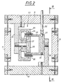
- FIG 2 is the X parallelogram with the associated Measuring force generator shown in detail in section.
- the by means of a connecting part (25) to the plate (9) attached fixed part (17) of the measuring force generator consists of a pot-like soft iron part (26) into which centrically a cylindrical permanent magnet (27) with a second soft iron part (28) is inserted. This creates a symmetrical of the field lines of the magnet (27) flowed through annular gap, in which also a cup-shaped Coil body is inserted.
- the bobbin (29) is over the connecting element (19) with the movable plate (10) connected to the x-guide.
- the coil body (29) also consists in Area of the annular gap, where he the turns (30) of Plunger coil, made of a good heat-conducting and electrical conductive material such as copper. That has two Advantages: on the one hand it allows in a relatively simple way by means of an annular groove in the coil body (29) soldered cooling tube (31) which arises in the coil (30) Dissipate heat by liquid cooling. This is the Cooling tube (31) with a flexible hose (32) one outside the probe, for example at the top the quill of the coordinate measuring device arranged heat exchanger connected.
- the copper coil body (29) as an eddy current brake and thus dampens the movements of the Plate (10) relative to the plate (9) of the parallelogram guide.
- the "clamping" of the Guide systems in given directions in any directions that are not necessarily related to the Guide directions x, y and z coincide.
- the trained as moving coils Measuring force generators in addition to passive damping the above-mentioned principle of the eddy current brake like an active speed proportional is also described Attenuation are switched on, the Damping behavior is specifically adjustable. Is made possible all of this by that described in Figures 4 and 5 microprocessor-controlled electronic control circuit.
- the system consists of a microprocessor (40), via a data bus with the one not shown here
- the coordinate measuring machine communicates.
- the Microprocessor (40) in turn controls three essentially identical electronic circuits, one of which is Circuit (41) for controlling the measuring force generator (17) is shown for the x-guide.
- the Microprocessor (40) on the circuit (41) on the position or momentary deflection of the guidance system x characterizing signal, i.e. the output signal of the Sensor (23) supplied.
- the Microprocessor (40) on the circuit (41) on the position or momentary deflection of the guidance system x characterizing signal, i.e. the output signal of the Sensor (23) supplied.
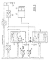
- FIG. 5 emerges, which is connected to a carrier frequency measuring amplifier (49) connected sensor (23) via a Analog / digital converter (50) with a data input of the Microprocessor connected.
- the circuit (41) receives three components (42, 43 and 44), each of which is generated by the measuring force generator (17) Measuring force possibly in connection with the function Damping as well as the clamping of the system can be adjusted.
- the electronic clamping is done by connecting one very strong, counteracting the measuring force, what corresponds to a spring curve with a very high slope, this characteristic curve then reaching the through the coils the measuring force generator (17) maximum flowing current is limited.
- the damping characteristic is generated by switching on one of the speed of the deflection of the guidance system proportional counterforce, increasing the strength of the damping can be set using the proportionality factor.
- K1 describes the size of the constant, deflection-independent measuring force
- K2 the Proportionality constant of the displacement-proportional Opposing force during clamping or measuring force generation simulate a spring characteristic
- K3 the strength of the speed-proportional damping.
- the information about the measuring force actually applied by the microprocessor (40) or processed on the computer of the coordinate measuring machine be used, for example, to correct the measuring force dependent bends of the stylus (13) or others elastic components of the coordinate measuring machine.
- the position measurement signal P x supplied by the carrier frequency measuring amplifier (49) is fed to a programmable amplifier (47) via a high-pass filter (48). Its gain factor can be adjusted according to the constant K3. In this way, the slope of the control characteristic F (v x ) can be set.
- the output of the programmable amplifier (47) is also connected to the input of the current amplifier (52) for the measuring force generator (17).
- a second programmable amplifier (45) is provided for setting the clamping force and the clamping direction.
- the strength of the clamping ie the steepness of the characteristic curve of the controller, is determined by the constant K2, which sets the gain factor of the programmable amplifier (45).
- K2 which sets the gain factor of the programmable amplifier (45).
- P Soll which is provided by a digital output of the microprocessor (40)
- a digital / analog converter (46) is converted by a digital / analog converter (46) into an analog signal and the input of the programmable amplifier (45). Its output is again connected to the input of the current amplifier (52).
- the output of the carrier frequency measuring amplifier (49) is connected to the input of the programmable amplifier (45), which thus receives a signal which is opposite to the deflection of the stylus (13) and which is amplified by the amplifier (45) to a very high degree.
- the microprocessor (40) calculates the preset value P target for the amplifier (45) from the information received from the analog / digital converter (50) about the current actual value P x of the deflection.
- P Soll is set to zero and every attempted displacement from this zero point generates a very high deflection-dependent counterforce via the analog control loop leading via the resistor (49) .
- P set is continuously set to the value of -P x .
- the Measuring force generators (15-17) designed as moving coil systems.
- the moving coils replaced by others electromagnetic drives such as linear motors etc. to replace.
Landscapes
- Physics & Mathematics (AREA)
- Engineering & Computer Science (AREA)
- General Physics & Mathematics (AREA)
- General Engineering & Computer Science (AREA)
- Electromagnetism (AREA)
- Acoustics & Sound (AREA)
- Aviation & Aerospace Engineering (AREA)
- Mechanical Engineering (AREA)
- Length Measuring Devices With Unspecified Measuring Means (AREA)
- A Measuring Device Byusing Mechanical Method (AREA)
- Measurement Of Length, Angles, Or The Like Using Electric Or Magnetic Means (AREA)
Description
- Figur 1
- ist eine perspektivische Prinzipsskizze, die den mechanischen Aufbau des Tastkopfs zeigt;
- Figur 2
- zeigt eine der Führungen des Tastkopfs aus Figur 1 mit dem ihr zugeordneten Kraftgenerator im Schnitt entlang der Symmetrieachse des Kraftgenerators;
- Figur 3
- ist eine Ansicht des Kraftgenerators aus Figur 2 entsprechend der Linie III in Figur 2;
- Figur 4
- ist ein vereinfachtes Blockschaltbild der zur Ansteuerung der Kraftgeneratoren verwendeten Elektronik;
- Figur 5
- ist eine detailliertere Schaltskizze der Elektronik aus Figur 4.

Claims (9)
- Tastkopf für Koordinatenmeßgeräte mit Meßsystemen (21-23) zur Messung der Auslenkung des nachgiebigen Teils des Tastkopfes, elektromagnetischen Kraftgeneratoren (15-17) zur Erzeugung von Meßkräften vorgebbarer Größe und Richtung sowie eine Einrichtung zum Fesseln bzw. Klemmen des nachgiebigen Teils in vorgebbaren Richtungen, wobeidadurch gekennzeichnet, daß die elektromagnetische Dämpfungseinrichtung nach dem Prinzip der Wirbelstrombremse arbeitet.der nachgiebige Teil (10) des Tastkopfes über ein Führungssystem in verschiedenen Richtungen auslenkbar ist und die Kraftgeneratoren direkt an den Führungen für die verschiedenen Richtungen (x,y,z) angeordnet sinddie Einrichtung zum Fesseln bzw. Klemmen eine elektronische Regelschaltung (43) umfaßt, die ein der Auslenkung des nachgiebigen Teils entgegengerichtetes Signal auf die Kraftgeneratoren aufschaltet, undder Tastkopf eine oder mehrere elektromagnetische Dämpfungseinrichtungen (29,44) für den nachgiebigen Teil enthält,
- Tastkopf nach Anspruch 1, wobei die Kraftgeneratoren (15-17) Tauchspulen sind, deren Spulenkörper (29) aus Metall bestehen.
- Tastkopf nach einem der Ansprüche 1-2, wobei die Tauchspulen an eine Kühleinrichtung (31,32) angeschlossen sind.
- Tastkopf nach einem der Ansprüche 2 oder 3, wobei die Spulen (30) oder der Spulenkörper (29) mit Röhren (31) für eine Kühlflüssigkeit verbunden sind.
- Tastkopf nach einem der Ansprüche 1-4, wobei die elektromagnetische Dämpfungseinrichtung eine elektronische Regelschaltung (44) umfaßt, die ein der Geschwindigkeit der Auslenkung des nachgiebigen Teils proportionales, der Auslenkrichtung entgegengerichtetes Signal auf die Kraftgeneratoren (15-17) aufschaltet.
- Tastkopf nach Anspruch 5, wobei die Dämpfungscharakteristik der Dämpfungseinrichtung (44) prozessorgesteuert einstellbar ist.
- Tastkopf nach einem der Ansprüche 1-6, wobei die Regelverstärkung der elektrischen Regelschaltung (43) zum Fesseln bzw. Klemmen prozessorgesteuert einstellbar ist.
- Tastkopf nach einem der Ansprüche 1-7, wobei zur Vorgabe der Meßkräfte in den einzelnen Koordinatenrichtungen (x,y,z), zur Einstellung der Klemmkräfte in den vorgebbaren Richtungen und zur Erzeugung der geschwindigkeitsabhängigen Dämpfung ein Mikroprozessor (40) dient, an dessen Ausgänge über entsprechende Treiberschaltungen die Kraftgeneratoren (15-17) angeschlossen sind, und der über eine Datenleitung mit dem Steuerrechner des Koordinatenmeßgeräts verbunden ist.
- Tastkopf nach einem der Ansprüche 1-8, wobei die Regelsignale für die Einstellung der Meß- und Klemmkräfte und der Dämpfung von den im Tastkopf vorhanden Meßsystemen (21-23) abgeleitet sind, die jeweils ein der Auslenkung des nachgiebigen Teils (10) in der jeweiligen Koordinatenrichtung proportionales Tastsignal liefern.
Applications Claiming Priority (2)
| Application Number | Priority Date | Filing Date | Title |
|---|---|---|---|
| DE4424225A DE4424225A1 (de) | 1994-07-09 | 1994-07-09 | Tastkopf für Koordinatenmeßgeräte |
| DE4424225 | 1994-07-09 |
Publications (3)
| Publication Number | Publication Date |
|---|---|
| EP0693669A2 EP0693669A2 (de) | 1996-01-24 |
| EP0693669A3 EP0693669A3 (de) | 1997-05-07 |
| EP0693669B1 true EP0693669B1 (de) | 2001-08-01 |
Family
ID=6522732
Family Applications (1)
| Application Number | Title | Priority Date | Filing Date |
|---|---|---|---|
| EP95109498A Expired - Lifetime EP0693669B1 (de) | 1994-07-09 | 1995-06-20 | Tastkopf für Koordinatenmessgeräte |
Country Status (4)
| Country | Link |
|---|---|
| US (1) | US5623766A (de) |
| EP (1) | EP0693669B1 (de) |
| JP (1) | JP3857334B2 (de) |
| DE (2) | DE4424225A1 (de) |
Cited By (1)
| Publication number | Priority date | Publication date | Assignee | Title |
|---|---|---|---|---|
| DE102011104228A1 (de) | 2011-05-13 | 2012-11-15 | Ludwig Nanopräzision GmbH | Vorrichtung zur Längenmessung und Verwendung der Vorrichtung zur Bestimmung physikalischer Eigenschaften von Messobjekten |
Families Citing this family (42)
| Publication number | Priority date | Publication date | Assignee | Title |
|---|---|---|---|---|
| DE19605776A1 (de) * | 1996-02-16 | 1997-08-21 | Zeiss Carl Fa | Koordinatenmeßgerät mit einem Taststift, dessen Orientierung einstellbar ist |
| DE19641720C2 (de) * | 1996-10-10 | 2002-01-24 | Mahr Gmbh | Tastkopf mit elektronischer Führung |
| EP0849654B1 (de) * | 1996-12-21 | 2004-04-28 | Carl Zeiss | Verfahren zur Steuerung von Koordinatenmessgeräten und Koordinatenmessgerät |
| EP0849653B1 (de) * | 1996-12-21 | 2004-04-28 | Carl Zeiss | Verfahren zur Steuerung eines Koordinatenmessgerätes und Koordinatenmessgerät |
| DE19721015C1 (de) * | 1997-05-20 | 1999-03-04 | Klingelnberg Soehne Gmbh | Universeller Tastkopf für Verzahnungsmessungen |
| DE19731005A1 (de) * | 1997-07-18 | 1999-02-11 | Leitz Brown & Sharpe Mestechni | Tastkopf für Koordinatenmeßgerät |
| JP2001124550A (ja) * | 1999-10-29 | 2001-05-11 | Matsushita Electric Ind Co Ltd | 傾斜センサ |
| US6434845B1 (en) * | 2000-09-05 | 2002-08-20 | University Of North Carolina At Charlotte | Dual-axis static and dynamic force characterization device |
| DE10100350A1 (de) * | 2001-01-05 | 2002-07-11 | Zeiss Carl | Tastkopf für ein Koordinatenmeßgerät |
| US6640459B1 (en) * | 2001-02-15 | 2003-11-04 | Fast Forward Devices, Llc | Multidimensional contact mechanics measurement system |
| DE10136559B4 (de) * | 2001-07-27 | 2011-08-11 | Carl Zeiss Industrielle Messtechnik GmbH, 73447 | Verfahren zum Diagnostizieren von Schäden in einem messenden Tastkopf eines Koordinatenmessgeräts |
| DE10140103C1 (de) * | 2001-08-16 | 2002-08-01 | Klingelnberg Gmbh | Zweiflanken-Wälzprüfgerät |
| DE10229824A1 (de) * | 2002-06-28 | 2004-01-15 | Carl Zeiss | Verfahren zum Betrieb eines in wenigstens zwei Betriebsarten betreibbaren Koordinatenmessgerätes |
| GB0221255D0 (en) * | 2002-09-13 | 2004-02-25 | Renishaw Plc | Touch Probe |
| US7178253B2 (en) * | 2002-10-29 | 2007-02-20 | Koninklijke Philips Electronics N.V. | Coordinate measuring device with a vibration damping system |
| JP3795008B2 (ja) * | 2002-11-28 | 2006-07-12 | アサ電子工業株式会社 | タッチセンサ |
| JP4330388B2 (ja) | 2003-07-28 | 2009-09-16 | 株式会社ミツトヨ | 倣いプローブ |
| DE102004011730A1 (de) | 2004-03-05 | 2005-09-22 | Carl Zeiss Industrielle Messtechnik Gmbh | Tastkopf für ein Koordinatenmessgerät |
| ATE354780T1 (de) * | 2004-12-15 | 2007-03-15 | Hexagon Metrology Gmbh | Messender tastkopf mit vibrationsdämpfung für ein koordinatenmessgerät |
| ATE487108T1 (de) * | 2005-07-08 | 2010-11-15 | Heidenhain Gmbh Dr Johannes | Tastkopf |
| DE102006055005A1 (de) | 2006-11-17 | 2008-05-29 | Carl Zeiss Industrielle Messtechnik Gmbh | Verfahren und Vorrichtung zum Bestimmen von Raumkoordinaten an einer Vielzahl von Messpunkten |
| DE102007013916B4 (de) * | 2007-03-20 | 2011-06-22 | Feinmess Suhl GmbH, 98527 | Konturenmessvorrichtung |
| DE102007022326B4 (de) | 2007-05-08 | 2022-07-07 | Carl Zeiss Industrielle Messtechnik Gmbh | Koordinatenmessgerät zum Bestimmen von Raumkoordinaten an einem Messobjekt sowie Dreh-Schwenk-Mechanismus für ein solches Koordinatenmessgerät |
| JP5645349B2 (ja) * | 2008-03-24 | 2014-12-24 | キヤノン株式会社 | 形状測定装置 |
| DE102008020250B4 (de) | 2008-04-22 | 2017-03-02 | Carl Zeiss Industrielle Messtechnik Gmbh | Koordinatenmessgerät mit manuell betätigbarem motorischen Antrieb |
| JP5270384B2 (ja) * | 2009-01-15 | 2013-08-21 | 株式会社ミツトヨ | 直線案内機構および測定装置 |
| DE102010006505B4 (de) | 2010-01-28 | 2013-09-19 | Carl Zeiss Industrielle Messtechnik Gmbh | Koordinatenmessgerät mit passivem Dreh-Schwenk-Mechanismus |
| WO2011098487A1 (de) | 2010-02-15 | 2011-08-18 | Carl Zeiss Industrielle Messtechnik Gmbh | Verfahren zum regeln eines messvorgangs mittels virtueller oberflächen |
| DE102010008751A1 (de) | 2010-02-15 | 2011-08-18 | Carl Zeiss Industrielle Messtechnik GmbH, 73447 | Verfahren zum Regeln eines Messvorgangs mittels virtueller Oberflächen |
| DE102010011841B4 (de) | 2010-03-11 | 2015-06-18 | Carl Zeiss Industrielle Messtechnik Gmbh | Verfahren zur Validierung eines Messergebnisses eines Koordinatenmessgeräts |
| CN103562672B (zh) | 2011-01-19 | 2016-09-28 | 瑞尼斯豪公司 | 用于机床设备的模拟测量探头 |
| USD685275S1 (en) * | 2011-04-29 | 2013-07-02 | Carl Zeiss Industrielle Messtechnik Gmbh | Probe head for coordinate measuring machine |
| JP2014081323A (ja) * | 2012-10-18 | 2014-05-08 | Mitsutoyo Corp | レバーヘッド |
| DE102013112188B4 (de) | 2013-11-06 | 2017-08-03 | Carl Zeiss Industrielle Messtechnik Gmbh | Verfahren zur Montage von Bauteilen mit Hilfe eines Koordinatenmessgeräts |
| JP6480169B2 (ja) * | 2014-12-04 | 2019-03-06 | 株式会社ミツトヨ | 三次元座標測定機用プローブヘッド |
| EP3034991B2 (de) | 2014-12-19 | 2022-08-24 | Hexagon Technology Center GmbH | Verfahren und Vorrichtung zum aktiven Entgegenwirken gegen Verlagerungskräfte mit einer Tasteinheit |
| EP3179203B1 (de) | 2015-12-11 | 2021-03-31 | TESA Sàrl | Gelenksondenkopf für messsystem |
| ES2709057T3 (es) * | 2016-04-18 | 2019-04-15 | Hexagon Metrology Gmbh | Dispositivo de medición de coordenadas con un cabezal de medición, así como procedimiento para medir una pieza de trabajo con un dispositivo de medición de coordenadas |
| DE102016223864A1 (de) * | 2016-11-30 | 2018-05-30 | Audi Ag | Aktives Schwingungsabsorptionssystem zur Absorption einer Schwingung eines schwingenden Elements sowie Kraftfahrzeug mit dem aktiven Schwingungsabsorptionssystem und Verfahren zum Betreiben des aktiven Schwingungsabsorptionssystems |
| JP6830386B2 (ja) * | 2017-03-27 | 2021-02-17 | 株式会社ミツトヨ | 測定ヘッド |
| EP3997414B1 (de) | 2019-07-12 | 2026-03-25 | Milwaukee Electric Tool Corporation | Bandmass mit magnetischem rückzugsgeschwindigkeitsregler |
| CN110823148B (zh) * | 2019-11-27 | 2021-02-05 | 合肥工业大学 | 一种测量传感器的五向碰撞保护机构 |
Citations (3)
| Publication number | Priority date | Publication date | Assignee | Title |
|---|---|---|---|---|
| DD150111A1 (de) * | 1980-04-08 | 1981-08-12 | Steffen Klawun | Einrichtung zur weg-kraft-koordinierung an antastsystemen |
| DE4001981A1 (de) * | 1989-01-25 | 1990-07-26 | Zeiss Carl Fa | Koordinatenmessgeraet |
| EP0569694A2 (de) * | 1992-04-14 | 1993-11-18 | Firma Carl Zeiss | Verfahren zur Messung von Formelementen auf einem Koordinatenmessgerät |
Family Cites Families (8)
| Publication number | Priority date | Publication date | Assignee | Title |
|---|---|---|---|---|
| DE2242355C2 (de) | 1972-08-29 | 1974-10-17 | Fa. Carl Zeiss, 7920 Heidenheim | Elektronischer Mehrkoordinatentaster |
| DE2356030C3 (de) * | 1973-11-09 | 1978-05-11 | Ernst Leitz Wetzlar Gmbh, 6330 Wetzlar | Taster zur Werkstückantastung |
| DE3210711C2 (de) * | 1982-03-24 | 1986-11-13 | Dr.-Ing. Höfler Meßgerätebau GmbH, 7505 Ettlingen | Mehrkoordinatentaster mit einstellbarer Meßkraft zum Abtasten von mehrdimensionalen, stillstehenden Gegenständen |
| DD226367A1 (de) * | 1984-08-01 | 1985-08-21 | Zeiss Jena Veb Carl | Anordnung zur erhoehung der steifigkeit von tastkoepfen |
| DD255784A1 (de) * | 1986-11-04 | 1988-04-13 | Zeiss Jena Veb Carl | Koordinatentastkopf mit einrichtung zur messkraftstabilisierung fuer koordinatenmessgeraete |
| DE3922297A1 (de) * | 1989-07-07 | 1991-01-17 | Zeiss Carl Fa | Elektromagnetische haltevorrichtung |
| JPH0792373B2 (ja) * | 1991-09-25 | 1995-10-09 | 株式会社ミツトヨ | タッチ信号プローブ |
| US5535524A (en) * | 1995-01-27 | 1996-07-16 | Brown & Sharpe Manufacturing Company | Vibration damper for coordinate measuring machine |
-
1994
- 1994-07-09 DE DE4424225A patent/DE4424225A1/de not_active Withdrawn
-
1995
- 1995-06-20 DE DE59509461T patent/DE59509461D1/de not_active Expired - Lifetime
- 1995-06-20 EP EP95109498A patent/EP0693669B1/de not_active Expired - Lifetime
- 1995-07-05 US US08/498,344 patent/US5623766A/en not_active Expired - Lifetime
- 1995-07-07 JP JP17243895A patent/JP3857334B2/ja not_active Expired - Lifetime
Patent Citations (3)
| Publication number | Priority date | Publication date | Assignee | Title |
|---|---|---|---|---|
| DD150111A1 (de) * | 1980-04-08 | 1981-08-12 | Steffen Klawun | Einrichtung zur weg-kraft-koordinierung an antastsystemen |
| DE4001981A1 (de) * | 1989-01-25 | 1990-07-26 | Zeiss Carl Fa | Koordinatenmessgeraet |
| EP0569694A2 (de) * | 1992-04-14 | 1993-11-18 | Firma Carl Zeiss | Verfahren zur Messung von Formelementen auf einem Koordinatenmessgerät |
Cited By (1)
| Publication number | Priority date | Publication date | Assignee | Title |
|---|---|---|---|---|
| DE102011104228A1 (de) | 2011-05-13 | 2012-11-15 | Ludwig Nanopräzision GmbH | Vorrichtung zur Längenmessung und Verwendung der Vorrichtung zur Bestimmung physikalischer Eigenschaften von Messobjekten |
Also Published As
| Publication number | Publication date |
|---|---|
| EP0693669A3 (de) | 1997-05-07 |
| EP0693669A2 (de) | 1996-01-24 |
| US5623766A (en) | 1997-04-29 |
| DE4424225A1 (de) | 1996-01-11 |
| JP3857334B2 (ja) | 2006-12-13 |
| JPH0843066A (ja) | 1996-02-16 |
| DE59509461D1 (de) | 2001-09-06 |
Similar Documents
| Publication | Publication Date | Title |
|---|---|---|
| DE4424225A1 (de) | Tastkopf für Koordinatenmeßgeräte | |
| EP1672310B1 (de) | Messender Tastkopf mit Vibrationsdämpfung für ein Koordinatenmessgerät | |
| EP0703517B1 (de) | Verfahren zur Messung von Werkstücken mit einem handgeführten Koordinatenmessgerät | |
| EP0242522B1 (de) | Vorrichtung zur Messung des Ortes, der Lage und/oder der Orts- bzw. Lageänderung eines starren Körpers im Raum | |
| DE3911341C1 (de) | ||
| DE2620099C2 (de) | Tastkopf mit allseitig auslenkbarem Taster | |
| DE2242355C2 (de) | Elektronischer Mehrkoordinatentaster | |
| EP0301390B1 (de) | Tastkopf für Koordinatenmessgeräte | |
| DE102017103938A1 (de) | Vorrichtung zum Messen der Rauheit einer Werkstückoberfläche | |
| EP1348104B1 (de) | Tastkopf für ein koordinatenmessgerät | |
| DE19529574A1 (de) | Koordinatenmeßgerät mit einer Steuerung, die den Tastkopf des Meßgeräts nach Solldaten verfährt | |
| DE69616925T2 (de) | Manuelle 3D-Koordinatenmessmaschine | |
| EP1322909B2 (de) | Koordinatenmessgerät | |
| DE3106031A1 (de) | Einrichtung zur weg-kraft-koordinierung an antastsystemen | |
| DE102004036796B3 (de) | Vorrichtung zum Entkoppeln eines Anbauelements von einem bewegbaren Maschinenelement | |
| DE3135180A1 (de) | Einrichtung zum linearen fuehren eines abtasters | |
| EP2124116B1 (de) | Verfahren zur Steuerung eines CNC-gesteuerten Koordinatenmessgerätes sowie Koordinatenmessgerät | |
| EP1264157B1 (de) | Tastkopf mit einer tarierung | |
| EP0297031A1 (de) | Werkzeug mit einer Sensorvorrichtung | |
| DE102019127499B4 (de) | Koordinatenmessgerät und Steuerungsverfahren eines Koordinatenmessgerätes | |
| DE3432842A1 (de) | X-y-flaechenantrieb mit begrenzter (phi)-drehung und z-verschiebung | |
| DE3740657A1 (de) | Koordinatentastkopf mit einrichtung zur messkraftstabilisierung fuer koordinatenmessgeraete | |
| DE4020527A1 (de) | Optische messmaschine | |
| DE19731005A1 (de) | Tastkopf für Koordinatenmeßgerät | |
| DE102011015973B4 (de) | Führung |
Legal Events
| Date | Code | Title | Description |
|---|---|---|---|
| PUAI | Public reference made under article 153(3) epc to a published international application that has entered the european phase |
Free format text: ORIGINAL CODE: 0009012 |
|
| AK | Designated contracting states |
Kind code of ref document: A2 Designated state(s): DE FR GB IT |
|
| PUAL | Search report despatched |
Free format text: ORIGINAL CODE: 0009013 |
|
| AK | Designated contracting states |
Kind code of ref document: A3 Designated state(s): DE FR GB IT |
|
| 17P | Request for examination filed |
Effective date: 19971016 |
|
| 17Q | First examination report despatched |
Effective date: 19990809 |
|
| RTI1 | Title (correction) |
Free format text: MEASURING HEAD FOR COORDINATE MEASURING MACHINES |
|
| GRAG | Despatch of communication of intention to grant |
Free format text: ORIGINAL CODE: EPIDOS AGRA |
|
| GRAG | Despatch of communication of intention to grant |
Free format text: ORIGINAL CODE: EPIDOS AGRA |
|
| GRAH | Despatch of communication of intention to grant a patent |
Free format text: ORIGINAL CODE: EPIDOS IGRA |
|
| RAP1 | Party data changed (applicant data changed or rights of an application transferred) |
Owner name: CARL-ZEISS-STIFTUNG TRADING AS CARL ZEISS Owner name: CARL ZEISS |
|
| GRAH | Despatch of communication of intention to grant a patent |
Free format text: ORIGINAL CODE: EPIDOS IGRA |
|
| GRAA | (expected) grant |
Free format text: ORIGINAL CODE: 0009210 |
|
| AK | Designated contracting states |
Kind code of ref document: B1 Designated state(s): DE FR GB IT |
|
| REF | Corresponds to: |
Ref document number: 59509461 Country of ref document: DE Date of ref document: 20010906 |
|
| GBT | Gb: translation of ep patent filed (gb section 77(6)(a)/1977) |
Effective date: 20011101 |
|
| EN | Fr: translation not filed | ||
| REG | Reference to a national code |
Ref country code: GB Ref legal event code: IF02 |
|
| EN | Fr: translation not filed |
Free format text: BO 01/52 PAGES: 283, IL Y A LIEU DE SUPPRIMER: LA MENTION DE LA NON REMISE. LA REMISE EST PUBLIEE DANS LE PRESENT BOPI. |
|
| ET | Fr: translation filed | ||
| PLBE | No opposition filed within time limit |
Free format text: ORIGINAL CODE: 0009261 |
|
| STAA | Information on the status of an ep patent application or granted ep patent |
Free format text: STATUS: NO OPPOSITION FILED WITHIN TIME LIMIT |
|
| 26N | No opposition filed | ||
| REG | Reference to a national code |
Ref country code: GB Ref legal event code: 732E |
|
| PGFP | Annual fee paid to national office [announced via postgrant information from national office to epo] |
Ref country code: FR Payment date: 20130703 Year of fee payment: 19 |
|
| PGFP | Annual fee paid to national office [announced via postgrant information from national office to epo] |
Ref country code: GB Payment date: 20140618 Year of fee payment: 20 |
|
| PGFP | Annual fee paid to national office [announced via postgrant information from national office to epo] |
Ref country code: DE Payment date: 20140619 Year of fee payment: 20 Ref country code: IT Payment date: 20140626 Year of fee payment: 20 |
|
| REG | Reference to a national code |
Ref country code: FR Ref legal event code: ST Effective date: 20150227 |
|
| PG25 | Lapsed in a contracting state [announced via postgrant information from national office to epo] |
Ref country code: FR Free format text: LAPSE BECAUSE OF NON-PAYMENT OF DUE FEES Effective date: 20140630 |
|
| REG | Reference to a national code |
Ref country code: DE Ref legal event code: R071 Ref document number: 59509461 Country of ref document: DE |
|
| REG | Reference to a national code |
Ref country code: GB Ref legal event code: PE20 Expiry date: 20150619 |
|
| PG25 | Lapsed in a contracting state [announced via postgrant information from national office to epo] |
Ref country code: GB Free format text: LAPSE BECAUSE OF EXPIRATION OF PROTECTION Effective date: 20150619 |