EP0691185A1 - Angetriebener Schrauber mit abgewinkeltem Kopf - Google Patents
Angetriebener Schrauber mit abgewinkeltem Kopf Download PDFInfo
- Publication number
- EP0691185A1 EP0691185A1 EP95850129A EP95850129A EP0691185A1 EP 0691185 A1 EP0691185 A1 EP 0691185A1 EP 95850129 A EP95850129 A EP 95850129A EP 95850129 A EP95850129 A EP 95850129A EP 0691185 A1 EP0691185 A1 EP 0691185A1
- Authority
- EP
- European Patent Office
- Prior art keywords
- holes
- group
- housing
- angle head
- pitch
- Prior art date
- Legal status (The legal status is an assumption and is not a legal conclusion. Google has not performed a legal analysis and makes no representation as to the accuracy of the status listed.)
- Granted
Links
- 230000013011 mating Effects 0.000 claims description 2
- 230000000717 retained effect Effects 0.000 claims 1
- 239000011295 pitch Substances 0.000 description 11
- 230000005540 biological transmission Effects 0.000 description 2
- 238000006073 displacement reaction Methods 0.000 description 2
- 238000006243 chemical reaction Methods 0.000 description 1
- 239000000463 material Substances 0.000 description 1
- 230000004048 modification Effects 0.000 description 1
- 238000012986 modification Methods 0.000 description 1
Images
Classifications
-
- B—PERFORMING OPERATIONS; TRANSPORTING
- B25—HAND TOOLS; PORTABLE POWER-DRIVEN TOOLS; MANIPULATORS
- B25F—COMBINATION OR MULTI-PURPOSE TOOLS NOT OTHERWISE PROVIDED FOR; DETAILS OR COMPONENTS OF PORTABLE POWER-DRIVEN TOOLS NOT PARTICULARLY RELATED TO THE OPERATIONS PERFORMED AND NOT OTHERWISE PROVIDED FOR
- B25F5/00—Details or components of portable power-driven tools not particularly related to the operations performed and not otherwise provided for
- B25F5/02—Construction of casings, bodies or handles
-
- B—PERFORMING OPERATIONS; TRANSPORTING
- B25—HAND TOOLS; PORTABLE POWER-DRIVEN TOOLS; MANIPULATORS
- B25B—TOOLS OR BENCH DEVICES NOT OTHERWISE PROVIDED FOR, FOR FASTENING, CONNECTING, DISENGAGING OR HOLDING
- B25B21/00—Portable power-driven screw or nut setting or loosening tools; Attachments for drilling apparatus serving the same purpose
Definitions
- This invention concerns an angle type power nutrunner having a housing with a rotation motor, an angle head with an output shaft, and a thread connection for securing the angle head to the housing and including mating threads on the angle head and the housing and a lock nut.
- Power nutrunners of this type are previously well known and may be exemplified by US Patent No. 4,064,948.
- the angle nutrunner disclosed in this patent lacks however a lock nut, which means that there is no provision made for angular adjustability of the angle head in relation to the tool housing.
- the thread connection between the angle head and the housing does comprise a lock nut to enable setting and securing of the angle head in desired angular positions.
- Such an adjustability of the angle head is important for the operator to obtain a comfortable working posture.
- This prior art nutrunner has a drawback in that it is difficult to have its angle head secured in a desired angular position during assembly of the tool. In other words, it is difficult to maintain the angle head in a correct desired angular position when tightening the lock nut.
- Alternative angular positions of the angle head are obtained by loosening the threaded sleeve and moving the angle head into a new position where another one of the teeth engages the lock pin, and then retightening the sleeve.
- Still another interesting piece of prior art refers to certain types of pneumatic chisel hammers wherein a thread connection between the cylinder of the impact mechanism and the tool handle comprises a lock pin which engages simultaneously one hole of a circumferential row of holes in the handle and one hole of a circumferential row of holes in the cylinder, wherein the pitch of the holes in the handle is different from the pitch of the holes in the cylinder.
- this previously known locking means has a certain resemblance with the present invention, it is important to notice that this known device is a pure thread locking device intended to be engaged after the thread connection has been firmly tightened and to maintain the thread connection in that firmly tightened state. This is very much the same thing as a cotter pin locking of a slotted nut and is not intended to define any other angular positions between the threaded parts than the fully tightened position.
- the main object of the invention is to accomplish an improved angle type power nutrunner having a thread connection between the angle head and the housing and including a positively acting position defining locking means.
- Another object of the invention is to accomplish an angle nutrunner with a positively acting angle head locking means which enables a small angle adjustment of the angle head relative to the housing.
- a thread connection between the angle head and the housing which includes a lock nut for securing the angle head in alternative angular positions relative to the housing and a radial key pin for defining positively such alternative angular positions by engaging simultaneously one of the holes of a first group of radial holes in either one of the angle head and the housing and one of the holes of a second group of radial holes in the other one of the angle head and the housing, whereby the holes of the first group of holes are circumferentially distributed at a certain pitch and the holes of the second group of holes are distributed at a pitch different from the pitch of the first group of holes.
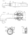
- Fig 1 shows a side view of an angle type power nutrunner according to the invention.
- Fig 2 shows, on a larger scale and partly in section, a side view of the forward part of the nutrunner.
- Fig 3 shows a side view of the rear end of the angle head.
- Fig 4 shows a cross section along line IV-IV in Fig 2.
- angle nutrunner shown in the drawing figures may be preumatically or electrically powered and contain any type of torque control means.
- the nutrunner comprises a cylindrical housing 10 provided with a rear handle 11. On the handle 11 there is supported a lever 12 by which a power control means (not shown) is activated. Within the housing 10 there is supported a rotation motor which via a power transmission is coupled to an output shaft 13. The latter is journalled in an angle head 15 and is formed with a square end for receiving a standard type nut socket.
- the angle head 15 contains a bevelled gear (not shown) which via a drive spindle 16 is coupled to a transmission shaft 17 in the housing 10.
- the rear end of the drive spindle 16 is journalled in a ball bearing 18 which is secured in the angle head 15 by a threaded ring 19.
- the rear end of the angle head 15 is formed with an outer thread for engagement with an inner thread cut in a neck portion 20 of the housing 10, thereby forming a thread connection 21 between the angle head 15 and the housing 10.
- This thread connection 21 also includes a lock nut 22 for firmly securing the angle head 15 to the housing 10 when tightened against the front end surface 23 of the neck portion 20.
- the holes of both the first group and second group are disposed in circumferentially directed rows and are arranged to be selectively engaged by a key pin 27 to define alternative angular positions of the angle head 15.
- a ring element in the form of a band 28 of a spring material is applied on the outside of the housing neck portion 20 to prevent the key pin 27 from falling out.
- the band 28 encompasses about 3/4 of the peripheri and is rotatably supported.
- the first group of holes 25 are three in number and spaced at a constant pitch of 30°.
- the holes 26 of the second group are eight in number and circumferentially distributed at a constant pitch of 45°. Accordingly, the pitch of the first group of holes 25 is 2/3 of the pitch of the second group of holes 26.
- Fig 3 there is illustrated that the holes 26 of the second group of holes are noncircular in cross section. Instead, they have a larger extent in the axial direction of the thread connection 21 so as to compensate for the inevitable axial displacement when turning the angle head 15.
- the rear end of the angle head 15 is threaded into the housing neck portion 20 to a level where the first and second groups of holew 25, 26 are substantially in the same transverse plane.
- the angle head 15 is turned into a desired angular position, and the key pin 27 is introduced through that one of the three holes 25 in the first group of holes that coincides with one of the holes 26 in the second group of holes in the angle head 15.
- the cover band 28 is rotated to a position where it covers the key pin 27 and retains the latter in locking position. Now, the desired angular postion of the angle head 15 is positively defined.
- the lock nut 22 is tightened against the front end surface 23 of the housing neck portion 20. Owing to the positive interlocking between the angle head 15 and the housing 10, tightening of the lock nut 22 will not cause any undesireable displacement of the angle head 15. The assembly of the nutrunner is thereby fascilitated.
- first and second groups of holes 25, 26 could be arranged in other patterns with other pitches and other numbers of holes.
- the pitches do not necessarily have to be constant.
Landscapes
- Engineering & Computer Science (AREA)
- Mechanical Engineering (AREA)
- Details Of Spanners, Wrenches, And Screw Drivers And Accessories (AREA)
Applications Claiming Priority (2)
| Application Number | Priority Date | Filing Date | Title |
|---|---|---|---|
| SE9402416A SE503326C2 (sv) | 1994-07-08 | 1994-07-08 | Vinkelmutterdragare |
| SE9402416 | 1994-07-08 |
Publications (2)
| Publication Number | Publication Date |
|---|---|
| EP0691185A1 true EP0691185A1 (de) | 1996-01-10 |
| EP0691185B1 EP0691185B1 (de) | 1998-01-21 |
Family
ID=20394671
Family Applications (1)
| Application Number | Title | Priority Date | Filing Date |
|---|---|---|---|
| EP95850129A Expired - Lifetime EP0691185B1 (de) | 1994-07-08 | 1995-07-10 | Angetriebener Schrauber mit abgewinkeltem Kopf |
Country Status (5)
| Country | Link |
|---|---|
| US (1) | US5577425A (de) |
| EP (1) | EP0691185B1 (de) |
| JP (1) | JPH08192368A (de) |
| DE (1) | DE69501485T2 (de) |
| SE (1) | SE503326C2 (de) |
Cited By (9)
| Publication number | Priority date | Publication date | Assignee | Title |
|---|---|---|---|---|
| US5577425A (en) * | 1994-07-08 | 1996-11-26 | Atlas Copco Tools Ab | Angle type power nutrunner |
| DE10124571A1 (de) * | 2001-05-14 | 2002-11-21 | C & E Fein Gmbh & Co Kg | Kraftgetriebener Winkelschrauber |
| US6715380B2 (en) | 2001-05-14 | 2004-04-06 | C. & E. Fein Gmbh & Co. Kg | Power-driven screwdriver |
| EP1369208A3 (de) * | 2002-06-07 | 2004-06-23 | Black & Decker Inc. | Kraftgetriebenes Werkzeug mit Blockiereinrichtung |
| FR2873052A1 (fr) * | 2004-07-15 | 2006-01-20 | Techway Ind Co Ltd | Cle a cliquet sans cordon |
| FR2889985A1 (fr) * | 2005-09-01 | 2007-03-02 | Georges Renault Soc Par Action | Ensemble d'outillage incluant une tete d'outil comprenant des moyens de positionnement angulaire de son arbre de transmission par rapport a un arbre moteur, et tete d'outil correspondante |
| WO2015036232A1 (de) * | 2013-09-11 | 2015-03-19 | Wagner Vermögensverwaltungs-GmbH & Co. KG | Drehschrauber sowie verfahren zum durchführen eines schraubvorgangs mit einem drehschrauber |
| WO2018228824A1 (en) * | 2017-06-12 | 2018-12-20 | Atlas Copco Industrial Technique Ab | Power wrench with adjustable trigger position |
| US11273540B2 (en) | 2017-06-12 | 2022-03-15 | Atlas Copco Industrial Technique Ab | Power wrench with angle drive |
Families Citing this family (13)
| Publication number | Priority date | Publication date | Assignee | Title |
|---|---|---|---|---|
| US6055887A (en) * | 1997-11-10 | 2000-05-02 | Galat; Donald E. | Power-operated wrench extension apparatus |
| US6089331A (en) * | 1998-08-06 | 2000-07-18 | Christ; Joseph T. | Apparatus and method for converting the drive direction axis of a rotational driving source |
| US7779731B1 (en) * | 2001-04-24 | 2010-08-24 | Gary Boccadutre | Power assisted lever arm ratchet |
| SE520640C2 (sv) * | 2001-10-16 | 2003-08-05 | Atlas Copco Tools Ab | Handhållet kraftverktyg med en roterande utgående axel |
| WO2003082653A1 (en) * | 2002-03-29 | 2003-10-09 | Dofasco Inc. | Vehicle hood safety prop |
| US6796385B1 (en) * | 2003-03-13 | 2004-09-28 | Alcoa Global Fasteners, Inc. | Fastener driving machine and associated method |
| GB2426797B (en) | 2005-06-01 | 2010-11-24 | Milwaukee Electric Tool Corp | Power tool |
| US8480453B2 (en) * | 2005-10-14 | 2013-07-09 | Sp Air Kabushiki Kaisha | Die grinder with rotatable head |
| US20070234854A1 (en) * | 2005-11-13 | 2007-10-11 | Ronny Collins | Bendable-head power ratchet tool |
| JP4926082B2 (ja) * | 2007-01-11 | 2012-05-09 | エス・ピー・エアー株式会社 | 回転可能なヘッドを持つダイグラインダ |
| DE102013213806A1 (de) * | 2012-11-15 | 2014-05-15 | Robert Bosch Gmbh | Werkzeugvorsatz für eine Handwerkzeugmaschine |
| US11759939B2 (en) * | 2018-06-29 | 2023-09-19 | Atlas Copco Industrial Technique Ab | Handheld electric power tool |
| US20210331300A1 (en) * | 2020-04-28 | 2021-10-28 | Snap-On Incorporated | Quick change indexable ratchet head |
Citations (6)
| Publication number | Priority date | Publication date | Assignee | Title |
|---|---|---|---|---|
| FR1519896A (fr) * | 1967-02-24 | 1968-04-05 | Dispositif de verrouillage de deux pièces vissées l'une sur l'autre | |
| DE2462678B1 (de) * | 1973-05-14 | 1980-10-30 | Thor Power Tool Co | Gehaeuseausbildung fuer ein kraftbetaetigtes Werkzeug,insbesondere Drehschrauber |
| EP0092736A1 (de) * | 1982-04-22 | 1983-11-02 | Robert Bosch Gmbh | Messwertgeber für Drehmoment- und/oder Drehwinkelmessung, insbesondere an motorgetriebenen Schraubern |
| US4458565A (en) | 1982-03-15 | 1984-07-10 | Robert Bosch Gmbh | Torque limiting power screwdriver |
| US4627761A (en) * | 1984-09-28 | 1986-12-09 | Snap-On Tools Corporation | Retainer |
| EP0511485A1 (de) * | 1991-04-29 | 1992-11-04 | C. & E. FEIN GmbH & Co. | Arretiereinrichtung für einen Winkelkopf |
Family Cites Families (4)
| Publication number | Priority date | Publication date | Assignee | Title |
|---|---|---|---|---|
| SE398208B (sv) * | 1975-03-18 | 1977-12-12 | Atlas Copco Ab | Skruv - eller mutterdragare |
| US4791836A (en) * | 1987-04-01 | 1988-12-20 | Chicago Pneumatic Tool Company | Ratchet mechanism |
| US5052496A (en) * | 1989-10-11 | 1991-10-01 | Ingersoll-Rand Company | Apparatus for attaching power tool housing extensions |
| SE503326C2 (sv) * | 1994-07-08 | 1996-05-28 | Atlas Copco Tools Ab | Vinkelmutterdragare |
-
1994
- 1994-07-08 SE SE9402416A patent/SE503326C2/sv not_active IP Right Cessation
-
1995
- 1995-07-07 US US08/499,434 patent/US5577425A/en not_active Expired - Fee Related
- 1995-07-10 DE DE69501485T patent/DE69501485T2/de not_active Expired - Fee Related
- 1995-07-10 EP EP95850129A patent/EP0691185B1/de not_active Expired - Lifetime
- 1995-07-10 JP JP7173530A patent/JPH08192368A/ja active Pending
Patent Citations (6)
| Publication number | Priority date | Publication date | Assignee | Title |
|---|---|---|---|---|
| FR1519896A (fr) * | 1967-02-24 | 1968-04-05 | Dispositif de verrouillage de deux pièces vissées l'une sur l'autre | |
| DE2462678B1 (de) * | 1973-05-14 | 1980-10-30 | Thor Power Tool Co | Gehaeuseausbildung fuer ein kraftbetaetigtes Werkzeug,insbesondere Drehschrauber |
| US4458565A (en) | 1982-03-15 | 1984-07-10 | Robert Bosch Gmbh | Torque limiting power screwdriver |
| EP0092736A1 (de) * | 1982-04-22 | 1983-11-02 | Robert Bosch Gmbh | Messwertgeber für Drehmoment- und/oder Drehwinkelmessung, insbesondere an motorgetriebenen Schraubern |
| US4627761A (en) * | 1984-09-28 | 1986-12-09 | Snap-On Tools Corporation | Retainer |
| EP0511485A1 (de) * | 1991-04-29 | 1992-11-04 | C. & E. FEIN GmbH & Co. | Arretiereinrichtung für einen Winkelkopf |
Cited By (13)
| Publication number | Priority date | Publication date | Assignee | Title |
|---|---|---|---|---|
| US5577425A (en) * | 1994-07-08 | 1996-11-26 | Atlas Copco Tools Ab | Angle type power nutrunner |
| DE10124571A1 (de) * | 2001-05-14 | 2002-11-21 | C & E Fein Gmbh & Co Kg | Kraftgetriebener Winkelschrauber |
| EP1260322A1 (de) * | 2001-05-14 | 2002-11-27 | C. & E. Fein Gmbh & Co. KG | Kraftgetriebener Winkelschrauber |
| US6715380B2 (en) | 2001-05-14 | 2004-04-06 | C. & E. Fein Gmbh & Co. Kg | Power-driven screwdriver |
| EP1369208A3 (de) * | 2002-06-07 | 2004-06-23 | Black & Decker Inc. | Kraftgetriebenes Werkzeug mit Blockiereinrichtung |
| US6938706B2 (en) | 2002-06-07 | 2005-09-06 | Black & Decker Inc. | Power tool provided with a locking mechanism |
| FR2873052A1 (fr) * | 2004-07-15 | 2006-01-20 | Techway Ind Co Ltd | Cle a cliquet sans cordon |
| FR2889985A1 (fr) * | 2005-09-01 | 2007-03-02 | Georges Renault Soc Par Action | Ensemble d'outillage incluant une tete d'outil comprenant des moyens de positionnement angulaire de son arbre de transmission par rapport a un arbre moteur, et tete d'outil correspondante |
| WO2007057241A1 (fr) * | 2005-09-01 | 2007-05-24 | Etablissements Georges Renault | Ensemble d'outillage incluant une tete d'outil comprenant des moyens de positionnement angulaire de son arbre de transmission par rapport a un arbre moteur, et tete d'outil correspondante |
| WO2015036232A1 (de) * | 2013-09-11 | 2015-03-19 | Wagner Vermögensverwaltungs-GmbH & Co. KG | Drehschrauber sowie verfahren zum durchführen eines schraubvorgangs mit einem drehschrauber |
| WO2018228824A1 (en) * | 2017-06-12 | 2018-12-20 | Atlas Copco Industrial Technique Ab | Power wrench with adjustable trigger position |
| US11273540B2 (en) | 2017-06-12 | 2022-03-15 | Atlas Copco Industrial Technique Ab | Power wrench with angle drive |
| US11607794B2 (en) | 2017-06-12 | 2023-03-21 | Atlas Copco Industrial Technique Ab | Power wrench with adjustable trigger position |
Also Published As
| Publication number | Publication date |
|---|---|
| EP0691185B1 (de) | 1998-01-21 |
| DE69501485D1 (de) | 1998-02-26 |
| DE69501485T2 (de) | 1998-09-17 |
| US5577425A (en) | 1996-11-26 |
| SE9402416L (sv) | 1996-01-09 |
| JPH08192368A (ja) | 1996-07-30 |
| SE503326C2 (sv) | 1996-05-28 |
| SE9402416D0 (sv) | 1994-07-08 |
Similar Documents
| Publication | Publication Date | Title |
|---|---|---|
| EP0691185B1 (de) | Angetriebener Schrauber mit abgewinkeltem Kopf | |
| EP1423223B1 (de) | Schlagverriegelungsspannfutter | |
| US5535867A (en) | Torque regulating coupling | |
| EP1159102B1 (de) | Spannfutter | |
| EP0886560B1 (de) | Angetriebener schraubenschlüssel mit drehmomentkupplung und einstellwerkzeug | |
| US7185896B2 (en) | Chuck with locking system | |
| EP0886559B1 (de) | Angetriebener schraubenschlüssel | |
| JP2001500803A (ja) | ばね式チャック | |
| US5788248A (en) | Collet chuck device | |
| JPH0283105A (ja) | 締め付け具 | |
| JPH07314220A (ja) | ドリルのような回転装置を装着するツールホルダーチャック | |
| GB2333729A (en) | A hand-guided drill with a spindle locking device | |
| WO1998047652A1 (en) | Quick release integrated collet and chuck device | |
| US4703942A (en) | Hammer drill | |
| US6739225B2 (en) | Screw driving tool | |
| WO2006089116A2 (en) | Drill chuck actuator | |
| GB2232625A (en) | Angle screwdriver | |
| GB2297513A (en) | Hand-held power tool with removable tool holder | |
| GB2276579A (en) | Tool carrier for an electrically operated hammer | |
| JPH08168971A (ja) | インパクトレンチ | |
| US12168283B2 (en) | Quick release socket | |
| JPH04360703A (ja) | 軸等の固定構造 | |
| JPS637203A (ja) | 締め付け具 | |
| US10850358B2 (en) | Spindle locking apparatus for a rotary power tool | |
| JPH02172604A (ja) | 締め付け具 |
Legal Events
| Date | Code | Title | Description |
|---|---|---|---|
| PUAI | Public reference made under article 153(3) epc to a published international application that has entered the european phase |
Free format text: ORIGINAL CODE: 0009012 |
|
| AK | Designated contracting states |
Kind code of ref document: A1 Designated state(s): DE FR GB IT |
|
| RIN1 | Information on inventor provided before grant (corrected) |
Inventor name: WALLERIUS, BENGT GOESTA Inventor name: HOLMIN, MATS CORNELIUS |
|
| 17P | Request for examination filed |
Effective date: 19960708 |
|
| GRAG | Despatch of communication of intention to grant |
Free format text: ORIGINAL CODE: EPIDOS AGRA |
|
| 17Q | First examination report despatched |
Effective date: 19970317 |
|
| GRAG | Despatch of communication of intention to grant |
Free format text: ORIGINAL CODE: EPIDOS AGRA |
|
| GRAH | Despatch of communication of intention to grant a patent |
Free format text: ORIGINAL CODE: EPIDOS IGRA |
|
| GRAH | Despatch of communication of intention to grant a patent |
Free format text: ORIGINAL CODE: EPIDOS IGRA |
|
| GRAA | (expected) grant |
Free format text: ORIGINAL CODE: 0009210 |
|
| AK | Designated contracting states |
Kind code of ref document: B1 Designated state(s): DE FR GB IT |
|
| REF | Corresponds to: |
Ref document number: 69501485 Country of ref document: DE Date of ref document: 19980226 |
|
| ITF | It: translation for a ep patent filed | ||
| ET | Fr: translation filed | ||
| PLBE | No opposition filed within time limit |
Free format text: ORIGINAL CODE: 0009261 |
|
| STAA | Information on the status of an ep patent application or granted ep patent |
Free format text: STATUS: NO OPPOSITION FILED WITHIN TIME LIMIT |
|
| 26N | No opposition filed | ||
| REG | Reference to a national code |
Ref country code: GB Ref legal event code: IF02 |
|
| PGFP | Annual fee paid to national office [announced via postgrant information from national office to epo] |
Ref country code: GB Payment date: 20030709 Year of fee payment: 9 |
|
| PGFP | Annual fee paid to national office [announced via postgrant information from national office to epo] |
Ref country code: FR Payment date: 20030711 Year of fee payment: 9 |
|
| PGFP | Annual fee paid to national office [announced via postgrant information from national office to epo] |
Ref country code: DE Payment date: 20030717 Year of fee payment: 9 |
|
| PG25 | Lapsed in a contracting state [announced via postgrant information from national office to epo] |
Ref country code: GB Free format text: LAPSE BECAUSE OF NON-PAYMENT OF DUE FEES Effective date: 20040710 |
|
| PG25 | Lapsed in a contracting state [announced via postgrant information from national office to epo] |
Ref country code: DE Free format text: LAPSE BECAUSE OF NON-PAYMENT OF DUE FEES Effective date: 20050201 |
|
| GBPC | Gb: european patent ceased through non-payment of renewal fee |
Effective date: 20040710 |
|
| PG25 | Lapsed in a contracting state [announced via postgrant information from national office to epo] |
Ref country code: FR Free format text: LAPSE BECAUSE OF NON-PAYMENT OF DUE FEES Effective date: 20050331 |
|
| REG | Reference to a national code |
Ref country code: FR Ref legal event code: ST |
|
| PG25 | Lapsed in a contracting state [announced via postgrant information from national office to epo] |
Ref country code: IT Free format text: LAPSE BECAUSE OF NON-PAYMENT OF DUE FEES;WARNING: LAPSES OF ITALIAN PATENTS WITH EFFECTIVE DATE BEFORE 2007 MAY HAVE OCCURRED AT ANY TIME BEFORE 2007. THE CORRECT EFFECTIVE DATE MAY BE DIFFERENT FROM THE ONE RECORDED. Effective date: 20050710 |