EP0689081A2 - Stereoskopische Anzeigevorrichtung - Google Patents
Stereoskopische Anzeigevorrichtung Download PDFInfo
- Publication number
- EP0689081A2 EP0689081A2 EP95108264A EP95108264A EP0689081A2 EP 0689081 A2 EP0689081 A2 EP 0689081A2 EP 95108264 A EP95108264 A EP 95108264A EP 95108264 A EP95108264 A EP 95108264A EP 0689081 A2 EP0689081 A2 EP 0689081A2
- Authority
- EP
- European Patent Office
- Prior art keywords
- display
- observers
- face images
- pairs
- arrayed
- Prior art date
- Legal status (The legal status is an assumption and is not a legal conclusion. Google has not performed a legal analysis and makes no representation as to the accuracy of the status listed.)
- Withdrawn
Links
Images


Classifications
-
- G—PHYSICS
- G02—OPTICS
- G02B—OPTICAL ELEMENTS, SYSTEMS OR APPARATUS
- G02B30/00—Optical systems or apparatus for producing three-dimensional [3D] effects, e.g. stereoscopic images
- G02B30/20—Optical systems or apparatus for producing three-dimensional [3D] effects, e.g. stereoscopic images by providing first and second parallax images to an observer's left and right eyes
- G02B30/22—Optical systems or apparatus for producing three-dimensional [3D] effects, e.g. stereoscopic images by providing first and second parallax images to an observer's left and right eyes of the stereoscopic type
- G02B30/24—Optical systems or apparatus for producing three-dimensional [3D] effects, e.g. stereoscopic images by providing first and second parallax images to an observer's left and right eyes of the stereoscopic type involving temporal multiplexing, e.g. using sequentially activated left and right shutters
-
- G—PHYSICS
- G02—OPTICS
- G02B—OPTICAL ELEMENTS, SYSTEMS OR APPARATUS
- G02B30/00—Optical systems or apparatus for producing three-dimensional [3D] effects, e.g. stereoscopic images
- G02B30/20—Optical systems or apparatus for producing three-dimensional [3D] effects, e.g. stereoscopic images by providing first and second parallax images to an observer's left and right eyes
- G02B30/26—Optical systems or apparatus for producing three-dimensional [3D] effects, e.g. stereoscopic images by providing first and second parallax images to an observer's left and right eyes of the autostereoscopic type
- G02B30/27—Optical systems or apparatus for producing three-dimensional [3D] effects, e.g. stereoscopic images by providing first and second parallax images to an observer's left and right eyes of the autostereoscopic type involving lenticular arrays
-
- G—PHYSICS
- G02—OPTICS
- G02B—OPTICAL ELEMENTS, SYSTEMS OR APPARATUS
- G02B30/00—Optical systems or apparatus for producing three-dimensional [3D] effects, e.g. stereoscopic images
- G02B30/20—Optical systems or apparatus for producing three-dimensional [3D] effects, e.g. stereoscopic images by providing first and second parallax images to an observer's left and right eyes
- G02B30/26—Optical systems or apparatus for producing three-dimensional [3D] effects, e.g. stereoscopic images by providing first and second parallax images to an observer's left and right eyes of the autostereoscopic type
- G02B30/33—Optical systems or apparatus for producing three-dimensional [3D] effects, e.g. stereoscopic images by providing first and second parallax images to an observer's left and right eyes of the autostereoscopic type involving directional light or back-light sources
-
- H—ELECTRICITY
- H04—ELECTRIC COMMUNICATION TECHNIQUE
- H04N—PICTORIAL COMMUNICATION, e.g. TELEVISION
- H04N13/00—Stereoscopic video systems; Multi-view video systems; Details thereof
- H04N13/30—Image reproducers
- H04N13/302—Image reproducers for viewing without the aid of special glasses, i.e. using autostereoscopic displays
-
- H—ELECTRICITY
- H04—ELECTRIC COMMUNICATION TECHNIQUE
- H04N—PICTORIAL COMMUNICATION, e.g. TELEVISION
- H04N13/00—Stereoscopic video systems; Multi-view video systems; Details thereof
- H04N13/30—Image reproducers
- H04N13/366—Image reproducers using viewer tracking
- H04N13/368—Image reproducers using viewer tracking for two or more viewers
Definitions
- the present invention relates to a stereoscopic display which enables observation of stereoscopic images without wearing special glasses or the like.
- This device includes a color liquid crystal plate for displaying stereo-pairs composed of right and left eye perspectives in time-interlaced manner, a monochrome TV display for displaying face images of each observer, and a large convex lens for directing the right and left eye perspectives to respective right and left eyes of each observer based on the face images of the monochrome TV display.
- This device enables simultaneous observation of stereoscopic images by plural persons without wearing special glasses.
- This device has a problem that the distance between the large convex lens and the monochrome TV display is large, because the large convex lens has a large focal length, thereby increasing the depth of the device undesirably.
- the stereoscopic display in accordance with the present invention includes stereo-pairs display means for selectively displaying stereo-pairs composed of right and left eye perspectives to be observed by observers, observers' face images display means for displaying observers' face images adapted to direct stereo-pairs displayed by the stereo-pairs display means to right and left eyes of the respective observers with accuracy, and arrayed focusing means for directing the stereo-pairs displayed by the stere-pairs display means to right and left eyes of each observer based on the observers' face images displayed by the observers' face images display means.
- the arrayed focusing means is situated on the plane from which it focuses observers' optical images substantially on a screen of the observers' face images display means in geometrical agreement with the observers' face images displayed thereby.
- the stereo-pairs display means is composed of transparent type electro-optical spatial modulation elements disposed between the observers and the arrayed focusing means to display the stereo-pairs in time-interlaced state
- the observers' face images display means is composed of a surface light source unit disposed behind the arrayed focusing means to display pairs of observers' face images of which flashing regions are inverted each other in time-interlaced manner.
- the transparent type electro-optical spatial modulation elements selectively use one of each pair of observers' face images displayed by the surface light source unit as back light so as to be synchronized with the time-interlaced display thereof.
- the surface light source unit is composed of a surface light source of which flashing regions are variable so as to be synchronized with the time-interlaced display of the electro-optical spatial modulation elements.
- the surface light source unit is composed of at least one light source and transparent type electro-optical spatial modulation elements provided on a light emission side of the at least one light source.
- the stereo-pairs display means is composed of transparent type electro-optical spatial modulation elements disposed between the observers and the arrayed focusing means to display the stereo-pairs in time-parallel state
- the observers' face images display means is composed of a surface light source unit which is disposed behind the arrayed focusing means to display pairs of observers' face images of which polarization axes are oriented approximately 90° with respect to each other.
- the transparent type electro-optical spatial modulation elements selectively use one of each pair of observers' face images displayed by the surface light source unit as back light.
- the surface light source unit includes a surface light source of which regions for emitting light rays of polarization axes oriented approximately 90° with respect to each other are variable, or includes a surface light source of which flashing regions are substantially variable and two polarization plates of which polarization axes are oriented approximately 90° so as to correspond to the displayed pairs of observers' face images.
- the surface light source unit is composed of a monochrome liquid crystal TV display, and in two polarization plates of the monochrome liquid crystal TV display, two kinds of regions of which polarization axes are oriented approximately 90° with respect to each other are distributed with uniformity.
- the transparent type electro-optical spatial modulation elements can be composed of a color liquid crystal image display plate wherein regions displaying left eye perspectives and those displaying right eye perspectives are alternately distributed with uniformity, and a polarizer on an input side thereof has such a member as to rotate polarization axes approximately 90° so as to correspond to the above regions of the color liquid crystal image display plate.
- the stereo-pairs display means is composed of transparent type electro-optical spatial modulation elements disposed between observers and the arrayed focusing means to display stereo-pairs in time-parallel state
- the observers' face images display means is composed of a surface light source unit disposed behind the arrayed focusing means to display pairs of observers' face images of which flashing regions are substantially inverted in time-interlaced manner.
- the transparent type electro-optical spatial modulation elements selectively use one of each pair of observer's face images displayed by the surface light source unit as back light so as to be synchronized with the time-interlaced display of the surface light source unit.
- an electro-optical spatial modulation element is further disposed between the surface light source unit and the spatial modulation elements for rotating the polarization axes of the pairs of observers' face images displayed by the surface light source unit approximately 90° so as to be synchronized with the time-interlaced display of the surface light source unit.
- the stereo-pairs display means is composed of transparent type electro-optical spatial modulation elements disposed between the observers and the arrayed focusing means to display the stereo-pairs in time-interlaced state
- the observers' face images display means is composed of a surface light source unit disposed behind the arrayed focusing means to display pairs of observers' face images of which polarization axes are oriented approximately 90° with respect to each other.
- a transparent type electro-optical spatial modulation element is further disposed between the surface light source unit and the spatical modulation elements for rotating the polarization axes of the pairs of observers' face images displayed by the surface light source unit approximately 90° so as to be synchronized with the time-interlaced display by the transparent type electro-optical spatial modulation elements.
- the stereoscopic display of the present invention can include taking means disposed in the vicinity of the arrayed focusing means for taking observers' face images continuously.
- the stereoscopic display of the present invention can include illuminating means disposed on at least one of right and left sides of the observers for illuminating observers' faces from at least one side thereof.
- the stereoscopic display of the present invention can include image modulation processing means for forming binary images based on the observers' face images taken by the taking means, and inputting the formed binary images into the observers' face images display means.
- the stereo-pairs displayed by the stereo-pairs display means in time-interlaced or time-parallel manner are directed selectively to left and right eyes of the respective observers with accuracy, while back-lighted by the observers' face images of the observers' face images display means. Since the focusing means has an arrayed configuration of which the focal length is less than that of a conventionally used large convex lens, the overall size of device in the direction of depth can be reduced.
- Any person positioned within the area where observers' optical images can be focused by the arrayed focusing means substantially on the screen of the observers' face images display means can observe stereoscopic images. Furthermore, he can observe such stereoscopic images continuously while moving his observation position unless he is outside of the above area. In addition, plural persons can observe stereoscopic images simultaneously.
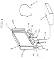
- FIGS. 1, 2 and 3 illustrate a first embodiment in accordance with the present invention. As shown, a color liquid crsytal plate 10 is disposed such that a screen thereof faces observers 12.
- An arrayed convex lens 14 is disposed behind the color liquid crystal plate 10, and a monochrome liquid crystal TV display 16 is disposed such that a screen thereof faces the arrayed convex lens 14 on the plane on which the arrayed convex lens 14 substantially focuses optical images of each observer 12.
- a polarization plate as an analyzer is detached from the monochrome liquid crystal TV display 16.
- An infrared TV camera 18 is disposed under the arrayed convex lens 14 such that arrayed taking lens thereof faces the observers 12.
- the arrayed taking lens has an arrangement similar to that of the arrayed convex lens 14.
- a matrix circuit 20 is connected to the color liquid crystal plate 10 to drive pixels thereof.
- a video tape recorder 22 which outputs a stere-pairs signal 24 is connected to the matrix circuit 20 by way of a stereoscopic synchronizing signal sampling circuit 26, whereby the stereo-pairs signal 24 is input to the matrix circuit 20.
- Observers' face images taken by the infrared TV camera 18 are input to a binary images forming circuit 28 to drive pixels of the monochrome liquid crystal TV display 16 in synchronization with a stereoscopic shynchronizing signal 30 output from the stereoscopic synchronizing signal sampling circuit 26. Furthermore, an infrared light source 32 is disposed on the obliquely right side of the observer 12.
- the color liquid crystal plate 10 serves as the stereo-pairs display means
- the monochrome liquid crystal TV display serves as the observers' face images display means
- the arrayed convex lens 14 serves as the arrayed focusing means.
- the stereo-pairs signal 24 from the video tape recoder 22 is input to the color liquid crystal plate 10 by way of the stereoscopic synchronizing signal sampling circuit 26 and the matrix circuit 20, whereby the color liquid crystal plate 12 displays stereo-pairs, each composed of right and left eye perspectives.
- Each observer 12 illuminated by the infrared light source 32 from the obliquely right side thereof is cntinuously taken by the infrared TV camera 18, and half face images of each observer 12, of which right half faces are bright while left half faces are dark, are obtained. Since the taking lens of the infrared TV camera 18 has an arrayed configuration similarly to the arrayed convex lens 14, the obtained half face images of each observer 12 are arranged similarly to the arrayed convex lens 14.
- the binary images forming circuit 28 outputs a binary and inverted binary images signal 36 based on an observer's face images signal 34 indicating the half face images of each observer 12 to the monochrome liquid crystal TV display 16 in time-interlaced manner in synchronization with the stereoscopic shynchronizing signal 30 from the stereoscopic synchronizing signal sampling circuit 26, whereby the screen of the monochrome liquid crystal TV display 16 displays obeservers' face images composed of binary and inverted binary images in time-interlaced manner.
- the arrayed convex lens 14 focuses plural optical images of each observer 12 substantially on the screen of the monochrome liquid crystal TV display 16.
- the arrayed convex lens 14 and the taking lens of the infrared TV camera 18 are disposed such that the plural optical images of each observer 12 are superimposed on the observer's binary and inverted binary images on the screen of the monochrome liquid crystal TV display 16 in geometrical agreement thereto.
- the monochrome liquid crystal TV display 16 is synchronized with the color liquid crystal plate 10 such that when the color liquid cystal plate 10 displays left eye perspectives, for example, the polarization axes of light rays emitted from the observer's left half face images on the screen of the monochrome liquid crystal TV display 16 are aligned with those of the polarizer of the color liquid crystal plate 10.
- the arrayed convex lens 14 focuses the bright left half face images from the monochrome liquid crystal TV display 16 on a left face of each observer 12 so that the above back light enters a left eye of each observer 12 selectively. This results in the left eye perspectives being seen only by the left eye of each observer 12. Likewise, the right eye perspectives are seen only by his right eye, whereby he can observe stereoscopic images without wearing any special glasses.
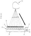
- any observer can observe stereoscopic images without wearing any special glasses provided that he is taken by the infrared TV camera 18 while being illuminated by the infrared light source 32 from his obliquely right side within the area where the arrayed convex lens 14 can focus the observer's optical images substantially on the screen of the monochrome liquid crystal TV display 16. He can also observe the stereoscopic images continuously while moving his location, unless he moves outside of the above area. Furthermore, plural persons can see the stereoscopic images simultaneously, as shown in FIG. 3 (in the drawing, a four-arrayed convex lens 14 is used).
- the analyzer is detached from the monochrome liquid crystal TV display 16.
- a normal monochrome liquid crystal TV display having an analyzer may be employed.
- the polarizer of the color liquid crystal plate 10 is detached therefrom, or the polarization axes of the polarizer of the color liquid crystal plate 10 are substantially aligned with those of the analyzer of the normal monochrome liquid crystal TV display.
- any means capable of outputing two dimensional images including at least three primary colors such as a plasma display, neon tubing display, solid state light emitting element, thin CRT or arrayed CRT, may be employed.
- FIGS. 4 and 5 illustrate a second embodiment in accordance with the present invention.
- a color liquid crystal plate 38 is disposed such that a screen thereof faces observers 12.
- the color liquid crystal plate 38 is connected to a video tape recorder 40 by way of a matrix circuit 20, whereby right and left eye perspectives composing stereo-pairs are output from the video tape recorder 40 to the color liquid crystal plate 38 in time-parallel manner.
- the color liquid crystal plate 38 displays the right and left eye perspectives in time-parallel and spatical-multiplex state. More specifically, alternate rows or columns of pixels (in FIG. 5, every row of pixels) of the color liquid crystal plate 38 display the right and left eye perspectives.
- a polarizer of the color liquid crystal plate 38 has an arrangement that polarization axes thereof are oriented approximately 90° with respect to each other so as to correspond to the above-described row or column of pixels of the color liquid crystal plate 38, whereby right eye perspectives display row or column and left eye perspectives display row or column, each having polarization axes different from each other, are alternately arranged in the polarizer of the color liquid crystal plate 38.
- An arrayed convex lens 14 is disposed behind the color liquid crystal plate 38.
- a monochrome liquid crystal TV display 42 is disposed such that a screen thereof faces the arrayed convex lens 14 on the plane on which the observers' optical images are substantially focused by the arrayed convex lens 14.
- the monochrome liquid crystal TV display 42 has two polarization plates of which polarization axes are alternately oriented approximately 90° with respect to each other so as to correspond to rows or columns of pixels of the monochrome liquid crystal TV display 42 substantially in alignment with the opposed polarization axes of the polarizer of the color liquid crystal plate 38.
- an infrared TV camera 18 having an arrayed taking lens and an infrared light source 32 are disposed in the vicinity of the arrayed convex lens 14 like the first embodiment.
- An observers' face images signal 34 obtained by the infrared TV camera 18 is input to a binary images signal forming circuit 28 to be converted to a binary and inverted binary images signal.
- the circuit 28 outputs a composite signal 37 to the monochrome liquid crystal TV display 42 such that rows or columns of pixels thereof alternately display binary and inverted binary images in time-parallel state. This results in observers' face images, each being composed of binary right and left half face images, being displayed alternately by rows or columns of pixels of the monochrome liquid crystal TV display 38.
- the infrared light source 32 and the binary images forming circuit 28 are adjusted such that the polarization axes of the rows or columns of pixels of the monochrome liquid crystal TV display 38, which display the left half face images, are substantially aligned with those of the left eye perspectives display rows or columns of the color liquid crystal plate 38 while the polarization axes of the rows or columns of pixels which display the right half face images are substantially aligned with those of the right eye perspectives display rows or columns of the color liquid crystal plate 38.
- the positions or the like of the arrayed convex lens 14 and the taking lens of the infrared TV camera 18 are adjusted such that the plural optical images of each observer 12 are superimposed substantially on the observer's half face images of the monochrome liquid crystal TV display 42.
- the light rays emitted from the observers' left half face images on the monochrome TV display 42 are transmitted only by the left eye perspectives display rows or columns of the color liquid crystal plate 38, of which the polarization axes are substantially aligned with those of the light rays emitted from the observers' left half face images of the monochrome TV display 42, thereby serving as back light for the left eye perspectives of the color liquid crystal plate 38.
- the left half face images for example, are focused by the arrayed convex lens 14 on a left half face of each observer 12, the left eye perspectives which are back-lighted by the light rays emitted from the observers' left half face images of the monochrome TV display 42 selectively enter a left eye of each observer 12.
- the right eye perspectives displayed by the color liquid crystal plate 38 selectively enter a right eye of each observer 12.
- each observer 12 can observe stereoscopic images. Furthermore, each observer 12 can observe stereoscopic images continuously while moving his observation position unless he is outside of the area described in the first embodiment. In addition, plural observers can observe stereoscopic images simultaneously like the first embodiment.
- the polarization axes of alternate rows or columns of pixels of the two polarization plates of the monochrome liquid crystal TV display are oriented approximately 90 with respect to each other.
- any other arrangement will do if the polarization axes corresponding to the binary half face images displaying pixels are oriented approximately 90° with respect to those corresponding to the inverted binary half face images displaying pixels.
- a normal monochrome liquid crystal TV display may be employed.
- a polarizing material which enables the rotation of the polarization axes approximately 90° with respect to each other.
- a monochrome CRT may be employed instead of the monochrome liquid crystal TV display.
- a polarization plate of which poralization axes are oriented similarly to the present invention is disposed on a screen of the monochrome CRT.
- the monochrome liquid crystal TV display from which an analyzer is detached may be employed.
- the binary half face images and their inverted binary images need not be displayed on the screen of the monochrome liquid crystal TV display in spatial-multiplexing state. Either the binary half face images or their inverted binary images will do.
- the stereo-pairs are input to the color liquid crystal plate from the video tape recorder in time-parallel manner.
- two image signals may be input in spatial-multiplexing manner.
- FIG. 6 illustrates a third embodiment of the present invention.
- a color liquid crystal plate 48 substantially identical to the color liquid crystal plate 38 of the second embodiment is connected to a video tape recorder (not shown) which is substantially identical to that (40) of the second embodiment via a matrix circuit (not shown).
- Alternate rows or columns of pixels (in FIG. 6, alternate rows of pixels) of the color liquid crystal plate 48 display right and left eye perspectives input from the video tape recorder in spatial-multiplexing and time-parallel state.
- a polarizer disposed on a light input side of the color liquid crystal plate 48 includes right and left eye perspectives display rows or columns of which polarization axes are oriented approximately 90° with respect to each other so as to correspond to the rows or columns of pixels of the color liquid crystal plate 48.
- An arrayed convex lens 14 is disposed behind the color liquid crystal plate 48.
- a normal monochrome liquid crystal TV display 50 is disposed on the plane on which the optical images of each observer 12 are substantially focused by the arrayed convex lens 14 such that the polarization axes of the light rays emitting from the monochrome liquid crystal TV display 50 are substantially aligned with one of two polarization axes of the polarizer of the color liquid crystal plate 48.
- An infrared TV camera 18 and an infrared light source are disposed in the vicinity of the arrayed convex lens 14 like the preceding embodiments.
- An devisver's images signal 34 is input to an binary images signal forming circuit 28.
- the binary images forming circuit 28 converts the observer's images signal 34 to a binary and inverted binary images signal 36 and input it to the monochrome liquid crystal TV display 50 in time-interlaced manner.
- a spatial modulation element 52 is further disposed between the monochrome liquid crystal TV display 50 and the arrayed convex lens 14 for rotating the polarization axes of transmitted light rays approximately 90° so as to be synchronized with the time-interlaced display of the binary and inverted binary images on the monochrome liquid crystal TV display 50.
- the polarization axes of the light rays emitted from a screen of the monochrome liquid crystal TV dsplay 50 in time-interlaced manner are rotated approximately 90° by the spatial modulation element 52.
- the polarization axes thereof are rotated approximately 90° by the spatial modulation element 52 substantially in alignment with those of the left eye perspectives display rows of the polarization plate of the color liquid crystal plate 48.
- the light rays emitted from the observers' left half face images on the monochrome liquid crystal TV display 50 pass the left eye perspectives display rows of the color liquid crystal plate 48 and acts as back light selectively for the color liquid crystal plate 48.
- the observers' left half face images are focused substantially on a left half face of each observer 12 by the arrayed convex lens 14. This causes the light rays emitted from the obserber's left half face images to be converged by the arrayed convex lens 14 and enter a left eye of each observer 12, whereby the left eye perspectives displayed by the color liquid crystal plate 48 are seen only by the left eye of each observer 12. Likewise, the right eye perspectives displayed by the color liquid crystal plate 48 are seen only by a right eye of each observer 12.
- each observer 12 can observe stereoscopic images. Furthermore, he can observe the stereoscopic images continuously if he moves his observation position, and plural observers can observe the stereoscopic images simultaneously like the preceding embodiments.
- the monochrome liquid crystal TV display can be replaced with a monochrome CRT.
- a monochrome CRT either binary half face images or their inverted binary images may be displayed on the monochrome CRT.
- FIG. 7 illustrates a fourth embodiment of the present invention.
- a color liquid crystal plate 54 identical to the color liquid crystal plate 10 of the first embodiment is connected to a video tape recorder (not shown) identical to the video tape recorder 22 of the first embodiment via a matrix circuit (not shown) to display right and left eye perspectives input from the video tape recorder alternately in time-interlaced state.
- An arrayed convex lens 14 is disposed behind the color liquid crystal plate 54.
- a monochrome liquid crystal TV display 56 identical to the monochrome liquid crystal TV display 42 of the second embodiment is disposed on the plane on which optical images of each observer 12 are substantially focused by the arrayed convex lens 14.
- the polarization axes of the two polarization plates of the monochrome liquid crystal TV display 56 are oriented approximately 90° with respect to each other so as to correspond to alternate rows or columns of pixels (in the drawing, alternate rows of pixels) thereof. And one of the polarization axes of the two polarization plates is substantially aligned with the polarization axis of a polarizer of the color liquid crystal plate 54.
- An infrared TV camera 18 and an infrared light source are disposed in the vicinity of the arrayed convex lens 14 to output an observers' face images signal 34 to a binary images forming circuit 28 like the preceding embodiments.
- the signal 34 is converted to binary and inverted binary images, and a composite signal 37 is output to the monochrome liquid crystal TV display 56 such that alternate rows or columns of pixels of the monochrome liquid crystal TV display 56 display binary right half face images and binary left half face images of each observer 12.
- a spatial modulation element 58 is further disposed between the monochrome liquid crystal TV display 56 and the arrayed convex lens 14 for rotating the polarization axes of the light rays emitted from the monochrome liquid crystal TV display 56 approximately 90° so as to be synchronized with the time-interlaced display of the right and left eye perspectives on the color liquid crystal plate 54.
- the polarization axes of the light rays emitted from the screen of the monochrome liquid crystal TV display 56 are rotated approximately 90° by the spatial modulation element 58 in time-interlaced state. Namely, when the color liquid crystal plate 54 displays left eye perspectives, for example, the polarization axes of the light rays emitted from the left half face images are substantially aligned with those of the polarizer of the color liquid crystal plate 54.
- the left half face images act as back light for the color liquid crystal plate 54. Since the observers' left half face images on the monochrome liquid crystal TV display 56 are focused on a left half face of each observer 12 by the arrayed convex lens 14, the light rays emitted from the left half face images as back light for the color liquid crystal plate 54 are converged by the arrayed convex lens 14 and enter a left eye of each observer 12. Thus, the left eye perspectives are seen only by the left eye of each observer 12. Likewise, the right eye perspectives of the color liquid crystal plate 54 are seen only by a right eye of each observer 12. As a result, each observer 12 can observe stereoscopic images similarly to the preceding embodiments. Furthermore, he can observe stereoscopic images continuously even if he moves his observation position, and plural persons can observe stereoscopic images simultaneously like the preceding embodiments.
- the polarization axes of alternate rows or columns of pixels of the two polarization plates of the monochrome liquid crystal TV display are oriented approximately 90° with respect to each other.
- the present invention is not limited to this arrangement provided that the biary half face images and their inverted images are polarized to be oriented approximately 90° with respect to each other.
- the polarization axes of the polarization plates may be oriented approximately 90° so as to correspond to every pixel of the monochrome liquid crystal TV display.
- a normal monochrome liquid crystal TV display provided with polarization plates can be employed. In this case, about one half of the screen of the analyzer thereof is covered with a polarization material capable of rotating the polarization axes thereof approximately 90°.
- the monochrome liquid crystal TV display may be replaced with such a monochrome CRT or the like as exemplified in the first embodiment.
- such a polarization plate as shown in the present embodiment is disposed on a screen of the monochrome CRT.
- the monochrome liquid crystal TV display provided with two polarization plates can be replaced with another monochrome liquid crystal TV display from which an analyzer is detached.
- both binary face images and their inverted images need not be displayed on a screen of the monochrome liquid crystal TV display in spatical-multiplexing state. Either binary face images or their inverted images will do.
- the arrayed convex lens may be replaced with an arrayed Fresnel convex lens or an arrayed Selfoc lens.
- Each arrayed lens is preferably composed of an integral lens, however, is not limited thereto.
- the arrayed convex lens may be replaced with a double integral lens array.
- the infrared TV camera as the taking means may be replaced with another TV camera which is sensitive to visible rays or ultraviolet rays. In this case, a light source emitting such rays is used as the illuminating means. The position and number of light sources can be arbitrarily selected.
- the arrayed lens as the taking lens of the TV camera may be replaced with a normal non-arrayed single lens.
- observers' face images taken by the TV camera are processed such that the monochrome liquid crystal TV display displays plural observers' face images so as to correspond to the observers' optical images focused by the arrayed convex lens.
- the monochrome liquid crystal TV display displays plural observers' face images so as to correspond to the observers' optical images focused by the arrayed convex lens.
- a normal non-arrayed single lens will do as the taking lens, and such processing is not needed.
- a half mirror may be provided on the optical axis of the arrayed lens such that a TV camera takes observers' images on the optical axis of the half mirror.
- the TV camera may be replaced with another taking system using microwave or ultrasonic wave.
- the TV camera may be also replaced with an automatically focusing camera which enables automatical adjustment of the distance between the monochrome liquid crystal TV display and the arrayed lens such that the observers' optical images are focused substantially on a screen of the monochrome liquid crystal TV display.
- the discrimination of the right and left half faces of each observer may be carried out by using image processing technique such as gravity wave detection.
- a large convex lens, Fresnel convex lens, Selfoc lens or arrayed lens thereof may be disposed on a screen of the monochrome liquid crystal TV display.
- pairs of observers' binary face images to be displayed on the screen of the monochrome liquid crystal TV display need not be composed of binary face images and their inverted images.
- two binary face images may be respectively obtained by using two TV cameras.
- the video tape recorder as the stereo-pairs forming means may be replaced with another member.
- the stereoscopic display is used as a display for one-way communication from a video tape recorder.
- the display of the present invention can be used as a TV display, stereoscopic display for domestic, industrial or medical use, and as a display for two-way communication such as multimedia, game machines, TV telephones, virtual reality or the like.
Landscapes
- Physics & Mathematics (AREA)
- Engineering & Computer Science (AREA)
- Multimedia (AREA)
- Signal Processing (AREA)
- General Physics & Mathematics (AREA)
- Optics & Photonics (AREA)
- Testing, Inspecting, Measuring Of Stereoscopic Televisions And Televisions (AREA)
- Liquid Crystal (AREA)
- Stereoscopic And Panoramic Photography (AREA)
Applications Claiming Priority (6)
| Application Number | Priority Date | Filing Date | Title |
|---|---|---|---|
| JP16268494 | 1994-06-20 | ||
| JP162684/94 | 1994-06-20 | ||
| JP270374/94 | 1994-10-06 | ||
| JP27037494 | 1994-10-06 | ||
| JP6312736A JPH08160556A (ja) | 1994-06-20 | 1994-11-22 | 立体映像表示装置 |
| JP312736/94 | 1994-11-22 |
Publications (2)
| Publication Number | Publication Date |
|---|---|
| EP0689081A2 true EP0689081A2 (de) | 1995-12-27 |
| EP0689081A3 EP0689081A3 (de) | 1998-05-20 |
Family
ID=27322040
Family Applications (1)
| Application Number | Title | Priority Date | Filing Date |
|---|---|---|---|
| EP95108264A Withdrawn EP0689081A3 (de) | 1994-06-20 | 1995-05-30 | Stereoskopische Anzeigevorrichtung |
Country Status (3)
| Country | Link |
|---|---|
| US (1) | US6445366B1 (de) |
| EP (1) | EP0689081A3 (de) |
| JP (1) | JPH08160556A (de) |
Cited By (2)
| Publication number | Priority date | Publication date | Assignee | Title |
|---|---|---|---|---|
| CN103747235A (zh) * | 2013-12-19 | 2014-04-23 | 黄松琪 | 利用普通信号形成立体视觉效果的电视机及其制作工艺 |
| CN104185007A (zh) * | 2014-06-07 | 2014-12-03 | 杭州立体世界科技有限公司 | 高清裸眼便携式立体影视播放器光路布局结构及光路线路 |
Families Citing this family (7)
| Publication number | Priority date | Publication date | Assignee | Title |
|---|---|---|---|---|
| US6752498B2 (en) * | 2001-05-14 | 2004-06-22 | Eastman Kodak Company | Adaptive autostereoscopic display system |
| US20050278091A1 (en) * | 2004-06-10 | 2005-12-15 | Visteon Global Technologies, Inc. | Dual image display |
| US7706677B2 (en) * | 2005-01-14 | 2010-04-27 | Samsung Electro-Mechanics Co., Ltd | Mobile communication terminal device |
| US8237779B2 (en) * | 2008-04-04 | 2012-08-07 | Texas Instruments Incorporated | Coding scheme for digital video signals and an image architecture using the same |
| JP4927208B2 (ja) * | 2010-09-30 | 2012-05-09 | 株式会社ナナオ | 立体画像表示装置 |
| JP5149435B1 (ja) * | 2011-11-04 | 2013-02-20 | 株式会社東芝 | 映像処理装置および映像処理方法 |
| KR101294261B1 (ko) * | 2013-01-08 | 2013-08-06 | 동서대학교산학협력단 | 마스크와 시간다중화 방식을 이용한 3차원 집적 영상 표시방법 |
Citations (3)
| Publication number | Priority date | Publication date | Assignee | Title |
|---|---|---|---|---|
| JPH06162684A (ja) | 1992-11-20 | 1994-06-10 | Canon Inc | 情報記録/再生方式 |
| JPH06270374A (ja) | 1993-03-23 | 1994-09-27 | Toppan Printing Co Ltd | 組版システム |
| JPH06312736A (ja) | 1993-04-28 | 1994-11-08 | Sony Corp | 簡易分割可能な包装箱 |
Family Cites Families (17)
| Publication number | Priority date | Publication date | Assignee | Title |
|---|---|---|---|---|
| US3959580A (en) * | 1973-08-20 | 1976-05-25 | Martin Marietta Corporation | Directly viewable stereoscopic projection system |
| US4562463A (en) * | 1981-05-15 | 1985-12-31 | Stereographics Corp. | Stereoscopic television system with field storage for sequential display of right and left images |
| US4649425A (en) * | 1983-07-25 | 1987-03-10 | Pund Marvin L | Stereoscopic display |
| GB8623490D0 (en) | 1986-09-30 | 1986-11-05 | Bass M L | Display means for stereoscopic images |
| US4750014A (en) * | 1986-10-20 | 1988-06-07 | Eastman Kodak Company | Optical device |
| US4945408A (en) * | 1987-06-26 | 1990-07-31 | Antonio Medina | Three dimensional stereoscopic video system with a single image sensor |
| US4799739A (en) * | 1987-08-10 | 1989-01-24 | Advanced Dimensional Displays, Inc. | Real time autostereoscopic displays using holographic diffusers |
| US4893183A (en) * | 1988-08-11 | 1990-01-09 | Carnegie-Mellon University | Robotic vision system |
| US4987487A (en) | 1988-08-12 | 1991-01-22 | Nippon Telegraph And Telephone Corporation | Method of stereoscopic images display which compensates electronically for viewer head movement |
| JP2513316B2 (ja) * | 1989-06-09 | 1996-07-03 | 富士ゼロックス株式会社 | 画像読取装置 |
| US5367315A (en) * | 1990-11-15 | 1994-11-22 | Eyetech Corporation | Method and apparatus for controlling cursor movement |
| JPH05122733A (ja) * | 1991-10-28 | 1993-05-18 | Nippon Hoso Kyokai <Nhk> | 3次元画像表示装置 |
| US5311220A (en) * | 1992-06-10 | 1994-05-10 | Dimension Technologies, Inc. | Autostereoscopic display |
| US5349379A (en) * | 1992-09-09 | 1994-09-20 | Dimension Technologies Inc. | Autostereoscopic display illumination system allowing viewing zones to follow the observer's head |
| JP3311832B2 (ja) | 1992-10-14 | 2002-08-05 | テルモ株式会社 | 立体画像表示装置 |
| GB2272597A (en) | 1992-11-11 | 1994-05-18 | Sharp Kk | 3-D Display apparatus. |
| US5421589A (en) * | 1993-05-14 | 1995-06-06 | The Walt Disney Company | Method and apparatus for displaying an alpha channel virtual image |
-
1994
- 1994-11-22 JP JP6312736A patent/JPH08160556A/ja active Pending
-
1995
- 1995-04-21 US US08/426,131 patent/US6445366B1/en not_active Expired - Fee Related
- 1995-05-30 EP EP95108264A patent/EP0689081A3/de not_active Withdrawn
Patent Citations (3)
| Publication number | Priority date | Publication date | Assignee | Title |
|---|---|---|---|---|
| JPH06162684A (ja) | 1992-11-20 | 1994-06-10 | Canon Inc | 情報記録/再生方式 |
| JPH06270374A (ja) | 1993-03-23 | 1994-09-27 | Toppan Printing Co Ltd | 組版システム |
| JPH06312736A (ja) | 1993-04-28 | 1994-11-08 | Sony Corp | 簡易分割可能な包装箱 |
Cited By (2)
| Publication number | Priority date | Publication date | Assignee | Title |
|---|---|---|---|---|
| CN103747235A (zh) * | 2013-12-19 | 2014-04-23 | 黄松琪 | 利用普通信号形成立体视觉效果的电视机及其制作工艺 |
| CN104185007A (zh) * | 2014-06-07 | 2014-12-03 | 杭州立体世界科技有限公司 | 高清裸眼便携式立体影视播放器光路布局结构及光路线路 |
Also Published As
| Publication number | Publication date |
|---|---|
| JPH08160556A (ja) | 1996-06-21 |
| EP0689081A3 (de) | 1998-05-20 |
| US6445366B1 (en) | 2002-09-03 |
Similar Documents
| Publication | Publication Date | Title |
|---|---|---|
| US6069649A (en) | Stereoscopic display | |
| US5774175A (en) | Stereoscopic television | |
| US6771231B2 (en) | Apparatus for displaying a stereoscopic two-dimensional image and method therefor | |
| US5568314A (en) | Image display apparatus | |
| US5546120A (en) | Autostereoscopic display system using shutter and back-to-back lenticular screen | |
| US5644427A (en) | Image display apparatus | |
| EP0656730B1 (de) | Stereoskopisches Bildanzeigesystem | |
| JPH0954376A (ja) | 立体表示装置 | |
| US5774262A (en) | Optical system for the two- and three-dimensional representation of information | |
| US10310369B2 (en) | Stereoscopic reproduction system using transparency | |
| US6445366B1 (en) | Stereoscopic display | |
| KR100440955B1 (ko) | 2d/3d 겸용 디스플레이 | |
| JPH0340692A (ja) | 立体画像表示方法 | |
| JP3708174B2 (ja) | 立体映像表示装置 | |
| JP2004258594A (ja) | 広角度から鑑賞できる立体画像表示装置 | |
| JP3463960B2 (ja) | 立体画像表示装置 | |
| JP3831853B2 (ja) | 立体映像表示装置 | |
| KR100293692B1 (ko) | 입체영상표시장치 | |
| KR970064285A (ko) | 3차원 영상 표시 장치 | |
| JPH11249593A (ja) | 表示装置および方法 | |
| US20040130506A1 (en) | Image display apparatus | |
| JP2000069505A (ja) | 立体画像表示装置 | |
| JPH08160355A (ja) | 立体映像表示装置 | |
| JPH0862534A (ja) | 立体画像表示装置 | |
| JPH095670A (ja) | 立体画像表示装置 |
Legal Events
| Date | Code | Title | Description |
|---|---|---|---|
| PUAI | Public reference made under article 153(3) epc to a published international application that has entered the european phase |
Free format text: ORIGINAL CODE: 0009012 |
|
| AK | Designated contracting states |
Kind code of ref document: A2 Designated state(s): DE FR IT |
|
| PUAL | Search report despatched |
Free format text: ORIGINAL CODE: 0009013 |
|
| AK | Designated contracting states |
Kind code of ref document: A3 Designated state(s): DE FR IT |
|
| 17P | Request for examination filed |
Effective date: 19981118 |
|
| 17Q | First examination report despatched |
Effective date: 19991213 |
|
| STAA | Information on the status of an ep patent application or granted ep patent |
Free format text: STATUS: THE APPLICATION IS DEEMED TO BE WITHDRAWN |
|
| 18D | Application deemed to be withdrawn |
Effective date: 19991005 |