EP0688713A2 - Fahrradnabenbremse - Google Patents
Fahrradnabenbremse Download PDFInfo
- Publication number
- EP0688713A2 EP0688713A2 EP95303935A EP95303935A EP0688713A2 EP 0688713 A2 EP0688713 A2 EP 0688713A2 EP 95303935 A EP95303935 A EP 95303935A EP 95303935 A EP95303935 A EP 95303935A EP 0688713 A2 EP0688713 A2 EP 0688713A2
- Authority
- EP
- European Patent Office
- Prior art keywords
- brake
- hub
- friction
- braking
- braking force
- Prior art date
- Legal status (The legal status is an assumption and is not a legal conclusion. Google has not performed a legal analysis and makes no representation as to the accuracy of the status listed.)
- Granted
Links
Images


Classifications
-
- B—PERFORMING OPERATIONS; TRANSPORTING
- B62—LAND VEHICLES FOR TRAVELLING OTHERWISE THAN ON RAILS
- B62L—BRAKES SPECIALLY ADAPTED FOR CYCLES
- B62L5/00—Brakes, or actuating mechanisms therefor, controlled by back-pedalling
- B62L5/10—Brakes, or actuating mechanisms therefor, controlled by back-pedalling the brakes being actuated through coacting cams and balls or rollers located in the rear wheel hub
-
- Y—GENERAL TAGGING OF NEW TECHNOLOGICAL DEVELOPMENTS; GENERAL TAGGING OF CROSS-SECTIONAL TECHNOLOGIES SPANNING OVER SEVERAL SECTIONS OF THE IPC; TECHNICAL SUBJECTS COVERED BY FORMER USPC CROSS-REFERENCE ART COLLECTIONS [XRACs] AND DIGESTS
- Y10—TECHNICAL SUBJECTS COVERED BY FORMER USPC
- Y10T—TECHNICAL SUBJECTS COVERED BY FORMER US CLASSIFICATION
- Y10T74/00—Machine element or mechanism
- Y10T74/19—Gearing
- Y10T74/19535—Follow-up mechanism
Definitions
- the present invention is directed to braking devices for bicycles and, more particularly, to a bicycle hub brake which includes a mechanism for preventing overbraking.
- a known bicycle hub brake is disclosed in Japanese Utility Model 2-35897.
- This bicycle hub brake includes a brake frame that supports a pair of brake shoes and a brake operation component.
- the brake shoes are disposed radially within a brake drum which rotates together with the bicycle wheel.
- the brake operation component pivots when a brake wire is pulled, and a cam surface on the brake operation component causes the brake shoes to move radially outwardly and press against the brake drum.
- the brake frame is connected to a support member through a spring so that, when a prescribed braking force is reached, the frictional contact between the brake shoe and the rotating brake drum causes the brake frame and brake shoes to move in the direction of the rotating drum against the force of the spring. This movement causes the brake operation device to move toward the brake wire housing which, in turn, creates slack in the brake wire to automatically reduce the frictional force between the brake shoe and the brake drum.
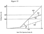
- Fig. 13 Operation of the prior art hub brake is shown graphically in Fig. 13.
- the inner wire operating stroke S is assigned to the horizontal axis, and the braking force B is assigned to the vertical axis.
- the braking force increases at a first angle of slope "a.”
- the braking force increases at a second angle of slope "b," where the slope "b" is smaller than the slope "a.”
- Some hub brakes use grease to control the frictional force between the brake shoe and the brake drum. When the grease is depleted, the frictional braking force increases excessively, and overbraking occurs. Even in brakes which are intended to operate without grease, rusting and dust penetration cause the frictional braking force to increase excessively, and overbraking again occurs. Fortunately, the known brake prevents such overbraking to a limited extent. For example, as indicated in Fig. 13, under normal conditions in which grease depletion or rusting has not occurred, the braking force is indicated by braking force line B2. When abnormal conditions prevail, the braking force is indicated by braking force line B1. The maximum braking force BX occurs in conventional hub brakes which do not have the compensation mechanism described above.
- braking force line B3 the maximum braking force created under abnormal conditions in a hub brake of the type described above is braking force BY, located at the top of braking force line B1, and this maximum braking force BY is lower than the maximum braking force BX which occurs in conventional hub brakes.
- a hub brake which employs the compensation mechanism described above tends to be relatively large, since the brake frame must be constructed to allow some movement, and some accommodation must be made to couple a free end of the brake frame to a spring. Thus, a more compact hub brake which prevents overbraking is desirable.
- the present invention is directed to a relatively compact hub brake which prevents overbraking.
- a rotating member rotates with a bicycle wheel
- a brake actuating mechanism causes a brake member to apply a braking force to a braking surface.
- An intermediate member is disposed between the brake actuating mechanism and the rotating member for moving relative to one of the brake actuating mechanism or the rotating member when a braking force less than a selected value is applied to the braking surface and for moving relative to the other one of the brake actuating mechanism or rotating member when a braking force greater than the selected value is applied to the braking surface.
- the intermediate member is disposed between the brake member and the rotating member, and the braking surface is disposed on the intermediate member.
- the intermediate member includes a surface which frictionally engages a surface of the rotating member
- the brake member includes a surface which frictionally engages the braking surface.
- a coefficient of friction or force of frictional contact between the surface of the intermediate member and the surface of the rotating member is ordinarily greater than a coefficient of friction or force of frictional contact between the surface of the brake member and the braking surface.
- a warning device may be coupled to the brake drum for providing a signal indicating when the brake drum moves relative to the intermediate member.
- the rotating member comprises a wheel hub
- the intermediate member comprises a brake drum having an inner peripheral surface comprising the braking surface.
- a torque limiter is disposed between the brake drum and the hub so that the brake drum rotates relative to the hub when a braking force greater than the selected value is applied to the braking surface.
- the torque limiter comprises a first friction member coupled to one of the brake drum or the hub and a second friction member coupled to the other one of the brake drum or the hub.
- the first friction member has a first friction surface which frictionally engages a second friction surface of the second friction member, and a spring biases the first friction surface and the second friction surface toward each other.
- the first and second friction members thus act as a clutch for allowing the brake drum to rotate relative to the hub when a braking force greater than the selected value is applied to the braking surface
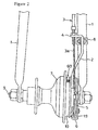
- FIG. 1 One embodiment of a bicycle hub brake according to the present invention is constructed as illustrated in Figures 1 and 2.
- a fixed component 2 is fixed to the bicycle front wheel fork 1 so that it does not move even when subjected to braking reaction force.
- the outer wire of a brake wire 3 is mounted in an outer holder 4 provided to the fixed component 2.
- An inner wire 3a is linked to a wire coupler 6 provided to a brake operation component 5 so that when the inner wire 3a is pulled or released, the brake operation component 5 slides so that the front wheel hub 7 is braked and the front wheel is in turn braked, or so that the brake is released from the front wheel hub 7 so that the brake is released from the front wheel.
- the fixed component 2 is constructed so as to be fixed to the front wheel fork 1 by a clamping band 8 at one end, as shown in Figure 1 and Figure 2, and by a mounting boss component 2a at the other, as shown in Figure 4. Specifically, it is constructed so that the mounting boss component 2a fits around the hub spindle 9 and so that the other end of the fixed component 2 is supported by the front wheel fork 1 via the hub spindle 9 .
- the clamping band 8 is mounted on the front wheel fork 1, and the fixed component 2 is attached to the front wheel fork 1 so that it does not rotate around the axis of the hub spindle 9 .
- the mounting boss component 2a is attached to the hub spindle 9 and the clamping band 8 is attached to the front wheel fork 1 so that the fixed component 2 is fixed to the front wheel fork 1 so as not to move even when subjected to braking reaction force.
- one end of the front wheel hub 7 is provided with an integrally formed brake drum 10 so that the brake drum 10 and the front wheel hub 7 rotate as an integrated unit.
- the space between the inside perimeter surface 10a of the brake drum 10 and the operating cam component 5a of the aforementioned brake operation component 5 is provided with a plurality of brake shoes 11 that are distributed along the perimeter of the brake drum 10 , a plurality of rollers 12 that are distributed along the perimeter of the brake drum 10 , such that two are located at the inside perimeter surface side of each brake shoe 11 , a roller case 13 which serves to maintain the intervals between the positioned rollers 12 at a prescribed interval and to retain the rollers 12 so that locational shift along the brake drum perimeter is prevented, and a ring-shaped sliding member 14 located on the outside perimeter surface side of the of brake shoes 11 .
- the brake operation component 5 comprises the aforementioned operating cam component 5a (which fits around a cone 15 and a cone fitting nut 16 ) and an operation arm component 5b that is capable of integrated motion extending from the operating cam component 5a whose protruding end side, as shown in Figure 3, extends past the fixed component 2 and the waterproof cap 17 through hole, is located on the lateral exterior bicycle frame side of the fixed component 2 , and is linked to the aforementioned wire coupler 6 .
- the tensing operation force of the aforementioned inner wire 3a shuttles the switch position around the axis of the hub spindle 9 from the off position OFF to the on position ON, and the action of a return spring 19 attached to the aforementioned mounting boss component 2a between the aforementioned waterproof cap 17 and a decorative cap 18 and with one end connected to the aforementioned wire coupler 6 serves to return to the brake off position OFF.
- a roller case fixing pin 20 extends from the roller case, passing through the fixed component 2 and waterproof cap 17 through holes and coming into contact with the fixed component 2 at the pin hole 2b end of the fixed component 2 . Since the fixed component 2 supports the rollers 12 via the roller case fixing pin 20 and the roller case 13 , and since a shoe pressing spring 21 that is wrapped around all of the brake shoes 11 pushes and forces the brake shoes 11 against the rollers 12 , some of the rollers 12 enter convex sections located on the inside perimeter surface side of the brake shoes 11 , engaging the brake shoes 11 , with the result that a braking operation in which the brake shoes 11 and the rollers 12 are applied against the rotation of the brake drum 10 in a stroke defined by the roller case fixing pin 20 moving within the pin hole 2b in opposition to the return spring 22 , without any additional movement.
- the aforementioned sliding member 14 is formed as a component separate from the brake shoes 11 and the brake drum 10 , and is inserted slidably in the brake drum 10 .
- the inside perimeter surface side of the sliding member 14 which faces the brake shoes 11 , is provided with a grease groove 23 as shown in Figure 7, break grease is stored between the brake shoes 11 and the sliding member 14 in the aforementioned grease groove 23 so that the brake shoes 11 rub against the sliding member 14 , with brake grease interposed, to effect braking action.
- the brake shoes 11 are fabricated from a chromium-molybdenum steel material, the sliding member 14 is fabricated from carbon steel, and the brake drum 10 is fabricated from an aluminum alloy.
- the sliding member 14 is inserted into the brake drum 10 so that relatively high frictional force between it and the inside perimeter surface 10a of the brake drum 10 can be readily obtained, and the outside perimeter surface of the sliding member 14 that is in contact with the brake drum 10 is coated with a solid lubricant 24 to stabilize the coefficient of friction, examples of which are hard chrome plating and molybdenum disulfide coating.
- the relationship between the coefficient of friction between the brake shoes 11 and the sliding member 14 when brake grease is present, f1, the coefficient of friction between the brake shoes 11 and the sliding member 14 when the brake grease is depleted, f3, and the coefficient of friction between the sliding member 14 and the brake drum 10 , f2, is set to conform to the equation: coefficient of friction f1 ⁇ coefficient of friction f2 ⁇ coefficient of friction f3.
- the brake operation component 5 presses the brake shoes 11 against the sliding member 14 via the rollers 12 with the operating cam component 5a .
- the frictional force F1 between the brake shoes 11 and the sliding member 14 is lower then the frictional force F2 between the sliding member 14 and the brake drum 10 , so the sliding member 14 rotates in conjunction with the brake drum 10 and the brake shoes 11 apply frictional braking force to the sliding member 14 , as a result of which the brake shoes 11 exert a braking action on the brake drum 10 via the sliding member 14 so that the front wheel is braked.
- the frictional force F3 between the brake shoes 11 and the sliding member 14 is greater then the frictional force F2 between the sliding member 14 and the brake drum 10 , the brake shoes 11 hold by friction the sliding member 14 so that it does not rotate in conjunction with the brake drum 10 , and the sliding member 14 applies frictional braking force to the brake drum 10 so that the front wheel is braked.
- the breaking operation can be conducted without overbraking.
- braking force B is generated by frictional force F2 between the sliding member 14 and the brake drum 10 and this frictional force F2 is greater than the aforementioned frictional force F1, so the braking force B in this event increases along braking force line B1, reaching a maximum at the maximum braking force BX1 afforded by tensing the inner wire 3a to the limit. Since the aforementioned frictional force F2 is greater than F1, the aforementioned maximum braking force BX1 is greater than the aforementioned maximum braking force BX2.
- the brake shoes 11 When the brake shoes 11 are made to perform direct braking action on the brake drum 10 in the absence of a sliding member 14 and the brake grease becomes depleted, the brake shoes 11 perform direct braking action on the brake drum 10 at the aforementioned frictional force F3, so an increase in the inner wire 3a tensing operation stroke S is accompanied by an increase in braking action B along braking force line B3, and when the inner wire 3a is pulled to the limit, the braking action B reaches the maximum braking force BX3.
- the maximum braking force BX3 at this time is a breaking force greater than the maximum braking force BX1 due to the relationship of magnitude between the aforementioned frictional forces F3 and F2.
- the aforementioned maximum braking force BX1 is set to afford a tire tangential force of approximately 45 kg, and maximum braking force BX2 to afford a tire tangential force of approximately 35 kg.
- a warning device 60 is constructed from a sphere 61 inserted into an attachment hole in the brake drum 10, a sphere pressing spring 63 that is constructed so as to subject the sphere 61 to pressing force towards the outer perimeter surface of the brake drum 10 and that is attached to the outer perimeter surface of the brake drum 10 by an attachment screw 62 , and a plurality of incised grooves 64 , as shown in Figure 7, that are formed on the outside perimeter surface side of the sliding member 14 at locations distributed along the circumference of the sliding member 14 .
- the sphere 61 does not undergo rotary motion with respect to the sliding member 14 and does not produce noise, and the warning device 60 is in non-operating mode.
- the brake grease is depleted, slip is produced between the sliding member 14 and brake drum 10 and the sliding member 14 and brake drum 10 rotate in relation to each other, whereupon the brake drum 10 rotates with respect to the sliding member 14 while retaining the sphere 61 so that the sphere 61 moves along the outer perimeter side of the sliding member 14 in the circumferential direction, passing the incised grooves 64 in the sliding member 14 .
- the pressing action of the sphere pressing spring 63 causes it to drop into the incised grooves 64 and collide with the sliding member 14 so that the collision of the sphere 61 with the sliding member 14 produces sound.
- the warning device 60 is placed in operating mode, and the sound of the collision of the sphere 61 with the sliding member 14 indicates grease depletion.
- the sliding member 14 and the brake shoes 11 are located inside the brake drum 10 , so the overall brake is compact. This is advantageous in terms of the space required for installation and in terms of the ease of handling with which it can be installed on the bicycle frame.
- an external fitting configuration in which the brake shoe is of band form and the brake shoe and sliding member are installed on the outside of the brake drum can be adopted.
- the sliding member is of ring shape, as in the embodiment described above, so it can simply be inserted into the brake drum without the use of any special mounting components or pressing operation component and installed so as to press against the brake drum to produce the desired frictional force.
- the brake is afforded with the advantage of structural simplicity.
- a plurality of sliding members may be installed distributed along the circumference of the brake drum.
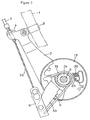
- Figures 9 and 10 show an alternative embodiment of a bicycle hub brake according to the present invention.
- the bicycle hub brake comprises a brake chassis 30 furnished with a brake drum 31 constructed so as to be located at one end of the bicycle front wheel hub 7 , and with brake shoes 11 , rollers 12 , a roller case 13 , a brake operation component 5 , and a fixed component 2 similar to those of the hub brake shown in Figures 2 through 5, and a torque limiter 40 , located between the aforementioned brake drum 31 of the chassis 30 and the aforementioned front wheel hub 7 and constructed so as to link the brake drum 31 to the front wheel hub 7 in integrated rotating fashion.
- the inside perimeter surface side (facing the brake shoes 11 ) of the brake drum 31 is provided with grease grooves 23 , as shown in Figure 9.
- Brake grease is stored between the brake drum 31 and the brake shoes 11 in the aforementioned grease grooves 23 so that the brake shoes 11 rub against the brake drum 31 and exert braking action in the presence of intervening brake grease.
- a ring member 41 that is designed to be connected to the front wheel hub 7 via a structure comprising a cylindrical member 50 for forming a ball receiver component 50a inside one end of the front wheel hub 7 which is connected by a screw connection at the connector section 50b of this member so as to rotate in integrated fashion, that is designed so that one of its ends fits into one end of the front wheel hub 7, and that is designed to fit over the end of the aforementioned cylindrical member 50 and to be stopped by the stopper surface 50c of the cylindrical member 50 , a friction plate 42 that fits further inside one end of the front wheel hub 7 than does the aforementioned ring member 41 and that fits over the aforementioned cylindrical member 50 , and a spring 43 that is located further inside the front wheel hub 7 than is the friction plate 42 and that fits around the outside of the cylindrical member 50 between the friction plate 42 and the aforementioned edge surface 7a of the front wheel hub 7 constitute the aforementioned torque limiter 40 .
- the ring member 41 fits so as to be capable of relative rotation with respect to the hub 7 and the cylindrical member 50 , and is engaged with the brake drum 31 via a spline component 31b so as to be capable of relative motion with respect to the hub 7 and so as to rotate together with the brake drum 31 .
- the friction plate 42 is engaged by a spline component 42a so as to be capable of integrated rotation and sliding with respect to the hub 7 and fits so as to be capable of relative rotation and sliding with respect to the cylindrical member 50 , so that, with respect to the hub 7 , it can slide in the direction of the hub axis only while rotating in integrated fashion with the hub 7 .
- the spring 43 presses the friction plate 42 against the side surface 41b of the ring member 41 , making it possible for the hub 7 rotational torque to be transmitted to the brake drum 31 by friction of the friction plate 42 and the ring member 41, and so that when the hub 7 rotational torque equals or exceeds the set torque value T determined by the coefficient of friction between the friction plate 42 and the ring member 41 and the pressing force of the spring 43 , the friction plate 42 and the ring member 41 experience slip and undergo relative rotation. That is, when the rotational torque of the front wheel hub 7 is lower than the set torque value T, the torque limiter 40 is activated so that the brake drum 31 and the hub 7 are frictionally linked so as to rotate in integrated fashion. If the hub 7 rotational torque equals or exceeds the set torque value T, the torque limiter 40 is deactivated so that the brake drum 31 and the hub 7 rotate in relation to each other.
- the torque limiter 40 is designed with a hub-housed configuration in which it is located inside one end of the hub 7 .
- the hub brake is compact and is easily attached to the bicycle frame in terms of the space required for attachment and in terms of ease of handling.
- This type of torque limiter can also be implemented by attaching the friction plate to the brake drum and attaching the ring member to the hub.
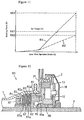
- the brake chassis 30 and the torque limiter 40 are constructed so that when brake grease is present and the brake shoes 11 contact the brake drum 31 with interposed brake grease, the brake chassis 30 yields the braking force curve B2 shown in Figure 11 and so that when the brake grease is depleted and the brake shoes 11 contact the brake drum 31 without interposed brake grease, the relationship between the braking force curve B yielded by the brake chassis 30 and the aforementioned set torque T torque limiter 40 is as illustrated in Figure 11.
- a warning device 70 is constructed from noise emitters 71 provided to the brake drum 31 at locations distributed along its circumference and a plurality of protrusions 72 provided to the hub 7 at locations distributed along its circumference.
- the torque limiter 40 When the torque limiter 40 is not in activated mode, the brake drum 31 and the hub 7 rotate in tandem due to friction plate 42 and ring member 41 friction so that the hub 7 does not undergo rotary motion with respect to the noise emitters 71.
- the warning device 70 is in non-operating mode.
- slip is produced between the friction plate 42 and the ring member 41 , and the brake drum 31 and the hub 7 rotate in relation to each other so that the hub 7 undergoes rotary motion with respect to the noise emitters 71 .
- the noise emitters 71 are bent by the protrusions 72 and vibrate so as to emit noise.
- the noise emitted by the noise emitters 71 serves to warn that the grease is depleted.
- FIG 12 shows another alternative embodiment of a bicycle hub brake according to the present invention which employs a torque limiter 80 .
- Torque limiter 80 comprises a ring component 81 housed in one end of the hub 7 , two hub-side friction plates 82 , two brake-side friction plates 83 , and a disc spring 84 located further towards the inside of the hub 7 than the friction plate pairs 82 and 83 .
- the ring component 81 is designed to be rotatably supported by the hub spindle 9 via a ball 85 and a cone 86 , fits in relatively rotating fashion inside one end of the hub 1 , and is linked in integrated rotating fashion to the brake drum 31 by a spline member 81a .
- the hub-side friction plates 82 are linked so as to be rotated in integrated fashion with respect to the hub 7 by a spline member 82a and so as to slide in the hub axis direction.
- the brake-side friction plates 83 are linked so as to be rotated in integrated fashion with respect to the ring component 81 by a spline member 83a and so as to slide in the hub axis direction.
- the spring 84 using a spring bracket 87 screwed onto the end of the ring component 81 as the reaction force component, exerts pressing force directly or indirectly on the hub-side friction plates 82 and the brake-side friction plates 83 against the side surface 81a of the ring component 81 so that the hub-side friction plates 82 and the brake-side friction plates 83 are pressed and friction is produced between the friction plate pairs 82 and 83 .
- the aforementioned set torque T is determined by the strength of the frictional force of the friction plates 82 and 83.
- the torque limiter 80 is thereby placed in non-operational mode and the brake drum 31 and the hub move in integrated fashion.
- rotation torque of the front wheel hub 7 is equal to or greater than the set torque T
- the friction plates 82 and 83 experience slip so that the hub 7 and the ring component 81 undergo relative rotation.
- the torque limiter 80 is thereby placed in operational mode and the brake drum 31 and the hub 7 undergo relative rotation
- the torque limiter can also be implemented using a positive-type clutch and a spring that biases the clutch towards the on position and sets the torque when the clutch is switched off.
- a hub-exterior type located on the outside of the hub can also be adopted.
- the warning device 60 or 70 can be omitted.
- the present invention can be implemented for hub brakes that are supplied with brake grease during use, as well as for hub brakes that are designed to be used without brake grease.
- the present invention can be implemented for brakes in which the brake shoes are pressed against the side of the brake drum by rollers, as in the foregoing embodiments, as well as for internal expanding brakes designed so that a plurality of brake shoes are pressed against or released from the inside of the brake drum by a rotating cam.
- the hub brake can be designed such that, under normal conditions, the frictional force between the sliding member and the brake shoes is greater than the frictional force between the sliding member and the brake drum. Furthermore, a means could be designed so that the coefficient of friction between the sliding member and the brake shoes and the coefficient of friction between the sliding member and the brake drum are the same, while the force of frictional contact of the brake shoes with the sliding member and the force of frictional contact of the sliding member with the brake drum are different. The effective result would be essentially the same.
Applications Claiming Priority (2)
| Application Number | Priority Date | Filing Date | Title |
|---|---|---|---|
| JP14131494A JP3638309B2 (ja) | 1994-06-23 | 1994-06-23 | 自転車用ハブブレーキ |
| JP141314/94 | 1994-06-23 |
Publications (3)
| Publication Number | Publication Date |
|---|---|
| EP0688713A2 true EP0688713A2 (de) | 1995-12-27 |
| EP0688713A3 EP0688713A3 (de) | 1997-05-14 |
| EP0688713B1 EP0688713B1 (de) | 1999-05-12 |
Family
ID=15289027
Family Applications (1)
| Application Number | Title | Priority Date | Filing Date |
|---|---|---|---|
| EP95303935A Expired - Lifetime EP0688713B1 (de) | 1994-06-23 | 1995-06-08 | Fahrradnabenbremse |
Country Status (6)
| Country | Link |
|---|---|
| US (1) | US5535855A (de) |
| EP (1) | EP0688713B1 (de) |
| JP (1) | JP3638309B2 (de) |
| CN (2) | CN1061613C (de) |
| DE (1) | DE69509588T2 (de) |
| TW (1) | TW277039B (de) |
Cited By (10)
| Publication number | Priority date | Publication date | Assignee | Title |
|---|---|---|---|---|
| EP1184276A3 (de) * | 2000-09-01 | 2003-01-08 | SRAM Deutschland GmbH | Bremseinrichtung für ein Fahrrad |
| EP1375330A1 (de) * | 2002-06-11 | 2004-01-02 | Shimano Inc. | Fahrradnabe mit daran angebrachter Kühlungsscheibe |
| EP1391325A2 (de) * | 2002-08-22 | 2004-02-25 | Shimano Inc. | Fahrradnabe mit einem von aussen regelbaren Bremsmechanismus |
| EP1733962A3 (de) * | 2005-06-17 | 2007-09-05 | Shimano Inc. | Antriebsvorrichtung für das Rad eines Fahrrads |
| EP1733957A3 (de) * | 2005-06-17 | 2007-12-12 | Shimano Inc. | Montageadapter für Rollenbremse |
| US7540361B2 (en) | 2005-06-17 | 2009-06-02 | Shimano Inc. | Roller brake mounting adapter |
| US7575106B2 (en) | 2005-06-17 | 2009-08-18 | Shimano Inc. | Bicycle wheel driving device |
| EP2228291A1 (de) * | 2009-03-11 | 2010-09-15 | Shimano, Inc. | Fahrradnabenbremse |
| NL1036445C2 (en) * | 2008-03-20 | 2010-10-26 | Hl Corp Shen Zhen | Bicycle front fork roller location structure. |
| EP1375935B2 (de) † | 2002-06-11 | 2010-11-24 | Shimano Inc. | Betätigungsvorrichtung für eine Fahrradsteuerungsvorrichtung |
Families Citing this family (20)
| Publication number | Priority date | Publication date | Assignee | Title |
|---|---|---|---|---|
| US5673773A (en) * | 1996-01-16 | 1997-10-07 | Valisum Industries Ltd. | Structure of a drum brake for bicycles |
| JPH09301256A (ja) * | 1996-05-09 | 1997-11-25 | Toshiba Tungaloy Co Ltd | 車両用ローラーブレーキ |
| JP3832909B2 (ja) * | 1996-10-04 | 2006-10-11 | 株式会社シマノ | 自転車用ブレーキ |
| JP3948501B2 (ja) * | 1997-08-07 | 2007-07-25 | Nskワーナー株式会社 | ブレーキドラム |
| SE515030C2 (sv) * | 1999-12-28 | 2001-05-28 | Tarmo Sjoeberg | Generator |
| JP3477134B2 (ja) | 2000-01-31 | 2003-12-10 | 株式会社シマノ | 自転車用ハブ |
| JP3626681B2 (ja) | 2000-12-27 | 2005-03-09 | 株式会社シマノ | 自転車用制動ケーブル係止具及び自転車用制動レバー |
| JP3654846B2 (ja) | 2001-03-22 | 2005-06-02 | 株式会社シマノ | 自転車用変速補助装置 |
| US6641500B2 (en) | 2001-12-27 | 2003-11-04 | Shimano, Inc. | Bicycle hub transmission with a power control mechanism for a shift assist mechanism |
| JP3740092B2 (ja) * | 2002-06-11 | 2006-01-25 | 株式会社シマノ | 自転車用ハブブレーキ装置 |
| JP3703780B2 (ja) * | 2002-06-11 | 2005-10-05 | 株式会社シマノ | 自転車用ハブブレーキ装置 |
| US20050269166A1 (en) * | 2004-06-08 | 2005-12-08 | Jui-Pin Chen | Adjustable disk brake assembly for a bicycle |
| ATE544861T1 (de) * | 2005-08-24 | 2012-02-15 | Pioneer Hi Bred Int | Verfahren und zusammensetzungen für den ausdruck eines polynukleotid von interesse |
| CA2530782A1 (en) * | 2005-12-14 | 2007-06-14 | Oil Lift Technology Inc. | Cam actuated centrifugal brake for wellhead drives |
| DE102009032844A1 (de) * | 2009-07-13 | 2011-01-20 | Maquet Gmbh & Co. Kg | Vorrichtung zur drehbaren Lagerung mindestens eines medizinischen Gerätes auf einem Boden und Verfahren zum Bremsen und/oder Feststellen einer Dreheinheit der Vorrichtung |
| US9651138B2 (en) | 2011-09-30 | 2017-05-16 | Mtd Products Inc. | Speed control assembly for a self-propelled walk-behind lawn mower |
| US9334908B2 (en) * | 2012-10-26 | 2016-05-10 | Kudu International Inc. | Centrifugal backspin brake |
| CN107839825B (zh) * | 2017-03-15 | 2023-04-07 | 慈溪市凯质车业有限公司 | 自行车涨刹花鼓总成 |
| JP6822931B2 (ja) * | 2017-09-28 | 2021-01-27 | 株式会社シマノ | ブレーキ装置 |
| JP7210154B2 (ja) * | 2018-04-10 | 2023-01-23 | 株式会社シマノ | 人力駆動車の回転装置 |
Citations (1)
| Publication number | Priority date | Publication date | Assignee | Title |
|---|---|---|---|---|
| JPH0235897U (de) | 1988-08-31 | 1990-03-08 |
Family Cites Families (6)
| Publication number | Priority date | Publication date | Assignee | Title |
|---|---|---|---|---|
| JPS5444912Y2 (de) * | 1977-03-11 | 1979-12-24 | ||
| JPH0138358Y2 (de) * | 1981-01-20 | 1989-11-16 | ||
| US4597477A (en) * | 1984-04-16 | 1986-07-01 | Sundstrand Corporation | Bidirectional brake |
| JP2742423B2 (ja) * | 1988-07-26 | 1998-04-22 | 松下電工株式会社 | パターン設定用端末器 |
| JP2934077B2 (ja) * | 1990-10-20 | 1999-08-16 | 株式会社シマノ | 自転車用動作装置に対する操作力取出装置 |
| JP2702350B2 (ja) * | 1992-03-23 | 1998-01-21 | 株式会社シマノ | 自転車用ブレーキ装置 |
-
1994
- 1994-06-23 JP JP14131494A patent/JP3638309B2/ja not_active Expired - Fee Related
-
1995
- 1995-02-28 TW TW084101938A patent/TW277039B/zh not_active IP Right Cessation
- 1995-06-02 US US08/456,641 patent/US5535855A/en not_active Expired - Lifetime
- 1995-06-08 DE DE69509588T patent/DE69509588T2/de not_active Expired - Lifetime
- 1995-06-08 EP EP95303935A patent/EP0688713B1/de not_active Expired - Lifetime
- 1995-06-22 CN CN95107690A patent/CN1061613C/zh not_active Expired - Fee Related
-
2000
- 2000-06-01 CN CN00117931.4A patent/CN1255299C/zh not_active Expired - Fee Related
Patent Citations (1)
| Publication number | Priority date | Publication date | Assignee | Title |
|---|---|---|---|---|
| JPH0235897U (de) | 1988-08-31 | 1990-03-08 |
Cited By (13)
| Publication number | Priority date | Publication date | Assignee | Title |
|---|---|---|---|---|
| EP1184276A3 (de) * | 2000-09-01 | 2003-01-08 | SRAM Deutschland GmbH | Bremseinrichtung für ein Fahrrad |
| EP1375935B2 (de) † | 2002-06-11 | 2010-11-24 | Shimano Inc. | Betätigungsvorrichtung für eine Fahrradsteuerungsvorrichtung |
| EP1375330A1 (de) * | 2002-06-11 | 2004-01-02 | Shimano Inc. | Fahrradnabe mit daran angebrachter Kühlungsscheibe |
| US6978867B2 (en) | 2002-06-11 | 2005-12-27 | Shimano, Inc. | Bicycle hub with an attached cooling disk |
| EP1391325A2 (de) * | 2002-08-22 | 2004-02-25 | Shimano Inc. | Fahrradnabe mit einem von aussen regelbaren Bremsmechanismus |
| EP1391325A3 (de) * | 2002-08-22 | 2005-05-04 | Shimano Inc. | Fahrradnabe mit einem von aussen regelbaren Bremsmechanismus |
| US7032719B2 (en) | 2002-08-22 | 2006-04-25 | Shimano, Inc. | Bicycle hub with an outside-accessible brake force adjusting mechanism |
| EP1733962A3 (de) * | 2005-06-17 | 2007-09-05 | Shimano Inc. | Antriebsvorrichtung für das Rad eines Fahrrads |
| US7540361B2 (en) | 2005-06-17 | 2009-06-02 | Shimano Inc. | Roller brake mounting adapter |
| US7575106B2 (en) | 2005-06-17 | 2009-08-18 | Shimano Inc. | Bicycle wheel driving device |
| EP1733957A3 (de) * | 2005-06-17 | 2007-12-12 | Shimano Inc. | Montageadapter für Rollenbremse |
| NL1036445C2 (en) * | 2008-03-20 | 2010-10-26 | Hl Corp Shen Zhen | Bicycle front fork roller location structure. |
| EP2228291A1 (de) * | 2009-03-11 | 2010-09-15 | Shimano, Inc. | Fahrradnabenbremse |
Also Published As
| Publication number | Publication date |
|---|---|
| JPH082471A (ja) | 1996-01-09 |
| US5535855A (en) | 1996-07-16 |
| EP0688713A3 (de) | 1997-05-14 |
| DE69509588D1 (de) | 1999-06-17 |
| CN1061613C (zh) | 2001-02-07 |
| CN1290628A (zh) | 2001-04-11 |
| CN1255299C (zh) | 2006-05-10 |
| CN1122299A (zh) | 1996-05-15 |
| EP0688713B1 (de) | 1999-05-12 |
| JP3638309B2 (ja) | 2005-04-13 |
| TW277039B (de) | 1996-06-01 |
| DE69509588T2 (de) | 2000-01-20 |
Similar Documents
| Publication | Publication Date | Title |
|---|---|---|
| EP0688713B1 (de) | Fahrradnabenbremse | |
| US4854423A (en) | Hydraulic disc brake drum-in-hat parking brake assembly | |
| US6378665B1 (en) | Pad retraction spring for disc brake assembly | |
| JP2008527278A (ja) | 高摩擦ブレーキシューアセンブリ | |
| CA1054957A (en) | Automatic brake adjusting mechanism | |
| JP2702350B2 (ja) | 自転車用ブレーキ装置 | |
| US4745992A (en) | Brake shoe assembly retainer and lining wear sensor | |
| US6719105B1 (en) | Pad retraction spring for disc brake assembly | |
| US20080087507A1 (en) | Disc brake assembly and method of assembly | |
| WO2014205176A1 (en) | Shared anchor bracket for a disc brake assembly having separate service and parking brake assemblies | |
| EP0628474B1 (de) | Fahrradbremsvorrichtung | |
| US5630486A (en) | Mechanical actuation device for drum brake | |
| US6196360B1 (en) | Automatic shoe clearance adjustment device for drum brakes | |
| US4350229A (en) | Disc brake having a slidably supported caliper | |
| JPS5831495B2 (ja) | ドラムブレ−キ | |
| EP0337320B1 (de) | Mechanismus zum Entriegeln der automatischen Verstellvorrichtung in einer Trommelbremse | |
| WO1998006608A2 (en) | Electro-mechanical actuation mechanism for disc brake assembly | |
| US6371257B1 (en) | Piston assembly for use in a wheel cylinder of a drum brake assembly | |
| JPH0122496B2 (de) | ||
| JPH0517410B2 (de) | ||
| JPS5838655B2 (ja) | ノリモノヨウエンバンブレ−キ | |
| US4371059A (en) | Automatic adjusting device in a disc brake | |
| US5226511A (en) | Spring activated automatic drum brake adjuster | |
| JPS643855Y2 (de) | ||
| US6241061B1 (en) | Reduced noise brake shoe assembly |
Legal Events
| Date | Code | Title | Description |
|---|---|---|---|
| PUAI | Public reference made under article 153(3) epc to a published international application that has entered the european phase |
Free format text: ORIGINAL CODE: 0009012 |
|
| AK | Designated contracting states |
Kind code of ref document: A2 Designated state(s): DE FR GB IT |
|
| PUAL | Search report despatched |
Free format text: ORIGINAL CODE: 0009013 |
|
| AK | Designated contracting states |
Kind code of ref document: A3 Designated state(s): DE FR GB IT |
|
| 17P | Request for examination filed |
Effective date: 19970531 |
|
| 17Q | First examination report despatched |
Effective date: 19980625 |
|
| GRAG | Despatch of communication of intention to grant |
Free format text: ORIGINAL CODE: EPIDOS AGRA |
|
| GRAG | Despatch of communication of intention to grant |
Free format text: ORIGINAL CODE: EPIDOS AGRA |
|
| GRAH | Despatch of communication of intention to grant a patent |
Free format text: ORIGINAL CODE: EPIDOS IGRA |
|
| GRAH | Despatch of communication of intention to grant a patent |
Free format text: ORIGINAL CODE: EPIDOS IGRA |
|
| GRAA | (expected) grant |
Free format text: ORIGINAL CODE: 0009210 |
|
| AK | Designated contracting states |
Kind code of ref document: B1 Designated state(s): DE FR GB IT |
|
| REF | Corresponds to: |
Ref document number: 69509588 Country of ref document: DE Date of ref document: 19990617 |
|
| ET | Fr: translation filed | ||
| PLBE | No opposition filed within time limit |
Free format text: ORIGINAL CODE: 0009261 |
|
| STAA | Information on the status of an ep patent application or granted ep patent |
Free format text: STATUS: NO OPPOSITION FILED WITHIN TIME LIMIT |
|
| 26N | No opposition filed | ||
| REG | Reference to a national code |
Ref country code: GB Ref legal event code: IF02 |
|
| PGFP | Annual fee paid to national office [announced via postgrant information from national office to epo] |
Ref country code: GB Payment date: 20050608 Year of fee payment: 11 |
|
| PG25 | Lapsed in a contracting state [announced via postgrant information from national office to epo] |
Ref country code: GB Free format text: LAPSE BECAUSE OF NON-PAYMENT OF DUE FEES Effective date: 20060608 |
|
| PGFP | Annual fee paid to national office [announced via postgrant information from national office to epo] |
Ref country code: IT Payment date: 20060630 Year of fee payment: 12 |
|
| GBPC | Gb: european patent ceased through non-payment of renewal fee |
Effective date: 20060608 |
|
| PGFP | Annual fee paid to national office [announced via postgrant information from national office to epo] |
Ref country code: FR Payment date: 20070608 Year of fee payment: 13 |
|
| REG | Reference to a national code |
Ref country code: FR Ref legal event code: ST Effective date: 20090228 |
|
| PG25 | Lapsed in a contracting state [announced via postgrant information from national office to epo] |
Ref country code: FR Free format text: LAPSE BECAUSE OF NON-PAYMENT OF DUE FEES Effective date: 20080630 |
|
| PG25 | Lapsed in a contracting state [announced via postgrant information from national office to epo] |
Ref country code: IT Free format text: LAPSE BECAUSE OF NON-PAYMENT OF DUE FEES Effective date: 20070608 |
|
| PGFP | Annual fee paid to national office [announced via postgrant information from national office to epo] |
Ref country code: DE Payment date: 20120607 Year of fee payment: 18 |
|
| REG | Reference to a national code |
Ref country code: DE Ref legal event code: R119 Ref document number: 69509588 Country of ref document: DE Effective date: 20140101 |
|
| PG25 | Lapsed in a contracting state [announced via postgrant information from national office to epo] |
Ref country code: DE Free format text: LAPSE BECAUSE OF NON-PAYMENT OF DUE FEES Effective date: 20140101 |