EP0685861B1 - Installationsschalter zur Befehlsgabe - Google Patents
Installationsschalter zur Befehlsgabe Download PDFInfo
- Publication number
- EP0685861B1 EP0685861B1 EP95107756A EP95107756A EP0685861B1 EP 0685861 B1 EP0685861 B1 EP 0685861B1 EP 95107756 A EP95107756 A EP 95107756A EP 95107756 A EP95107756 A EP 95107756A EP 0685861 B1 EP0685861 B1 EP 0685861B1
- Authority
- EP
- European Patent Office
- Prior art keywords
- switch according
- installation
- installation switch
- further operating
- elements
- Prior art date
- Legal status (The legal status is an assumption and is not a legal conclusion. Google has not performed a legal analysis and makes no representation as to the accuracy of the status listed.)
- Expired - Lifetime
Links
Images

Classifications
-
- H—ELECTRICITY
- H01—ELECTRIC ELEMENTS
- H01H—ELECTRIC SWITCHES; RELAYS; SELECTORS; EMERGENCY PROTECTIVE DEVICES
- H01H3/00—Mechanisms for operating contacts
- H01H3/02—Operating parts, i.e. for operating driving mechanism by a mechanical force external to the switch
-
- H—ELECTRICITY
- H01—ELECTRIC ELEMENTS
- H01H—ELECTRIC SWITCHES; RELAYS; SELECTORS; EMERGENCY PROTECTIVE DEVICES
- H01H23/00—Tumbler or rocker switches, i.e. switches characterised by being operated by rocking an operating member in the form of a rocker button
- H01H23/02—Details
- H01H23/04—Cases; Covers
-
- H—ELECTRICITY
- H02—GENERATION; CONVERSION OR DISTRIBUTION OF ELECTRIC POWER
- H02J—CIRCUIT ARRANGEMENTS OR SYSTEMS FOR SUPPLYING OR DISTRIBUTING ELECTRIC POWER; SYSTEMS FOR STORING ELECTRIC ENERGY
- H02J13/00—Circuit arrangements for providing remote indication of network conditions, e.g. an instantaneous record of the open or closed condition of each circuitbreaker in the network; Circuit arrangements for providing remote control of switching means in a power distribution network, e.g. switching in and out of current consumers by using a pulse code signal carried by the network
- H02J13/00006—Circuit arrangements for providing remote indication of network conditions, e.g. an instantaneous record of the open or closed condition of each circuitbreaker in the network; Circuit arrangements for providing remote control of switching means in a power distribution network, e.g. switching in and out of current consumers by using a pulse code signal carried by the network characterised by information or instructions transport means between the monitoring, controlling or managing units and monitored, controlled or operated power network element or electrical equipment
-
- H—ELECTRICITY
- H02—GENERATION; CONVERSION OR DISTRIBUTION OF ELECTRIC POWER
- H02J—CIRCUIT ARRANGEMENTS OR SYSTEMS FOR SUPPLYING OR DISTRIBUTING ELECTRIC POWER; SYSTEMS FOR STORING ELECTRIC ENERGY
- H02J13/00—Circuit arrangements for providing remote indication of network conditions, e.g. an instantaneous record of the open or closed condition of each circuitbreaker in the network; Circuit arrangements for providing remote control of switching means in a power distribution network, e.g. switching in and out of current consumers by using a pulse code signal carried by the network
- H02J13/00032—Systems characterised by the controlled or operated power network elements or equipment, the power network elements or equipment not otherwise provided for
- H02J13/00036—Systems characterised by the controlled or operated power network elements or equipment, the power network elements or equipment not otherwise provided for the elements or equipment being or involving switches, relays or circuit breakers
-
- H—ELECTRICITY
- H01—ELECTRIC ELEMENTS
- H01H—ELECTRIC SWITCHES; RELAYS; SELECTORS; EMERGENCY PROTECTIVE DEVICES
- H01H2300/00—Orthogonal indexing scheme relating to electric switches, relays, selectors or emergency protective devices covered by H01H
- H01H2300/03—Application domotique, e.g. for house automation, bus connected switches, sensors, loads or intelligent wiring
-
- Y—GENERAL TAGGING OF NEW TECHNOLOGICAL DEVELOPMENTS; GENERAL TAGGING OF CROSS-SECTIONAL TECHNOLOGIES SPANNING OVER SEVERAL SECTIONS OF THE IPC; TECHNICAL SUBJECTS COVERED BY FORMER USPC CROSS-REFERENCE ART COLLECTIONS [XRACs] AND DIGESTS
- Y02—TECHNOLOGIES OR APPLICATIONS FOR MITIGATION OR ADAPTATION AGAINST CLIMATE CHANGE
- Y02B—CLIMATE CHANGE MITIGATION TECHNOLOGIES RELATED TO BUILDINGS, e.g. HOUSING, HOUSE APPLIANCES OR RELATED END-USER APPLICATIONS
- Y02B90/00—Enabling technologies or technologies with a potential or indirect contribution to GHG emissions mitigation
- Y02B90/20—Smart grids as enabling technology in buildings sector
-
- Y—GENERAL TAGGING OF NEW TECHNOLOGICAL DEVELOPMENTS; GENERAL TAGGING OF CROSS-SECTIONAL TECHNOLOGIES SPANNING OVER SEVERAL SECTIONS OF THE IPC; TECHNICAL SUBJECTS COVERED BY FORMER USPC CROSS-REFERENCE ART COLLECTIONS [XRACs] AND DIGESTS
- Y04—INFORMATION OR COMMUNICATION TECHNOLOGIES HAVING AN IMPACT ON OTHER TECHNOLOGY AREAS
- Y04S—SYSTEMS INTEGRATING TECHNOLOGIES RELATED TO POWER NETWORK OPERATION, COMMUNICATION OR INFORMATION TECHNOLOGIES FOR IMPROVING THE ELECTRICAL POWER GENERATION, TRANSMISSION, DISTRIBUTION, MANAGEMENT OR USAGE, i.e. SMART GRIDS
- Y04S20/00—Management or operation of end-user stationary applications or the last stages of power distribution; Controlling, monitoring or operating thereof
- Y04S20/14—Protecting elements, switches, relays or circuit breakers
-
- Y—GENERAL TAGGING OF NEW TECHNOLOGICAL DEVELOPMENTS; GENERAL TAGGING OF CROSS-SECTIONAL TECHNOLOGIES SPANNING OVER SEVERAL SECTIONS OF THE IPC; TECHNICAL SUBJECTS COVERED BY FORMER USPC CROSS-REFERENCE ART COLLECTIONS [XRACs] AND DIGESTS
- Y04—INFORMATION OR COMMUNICATION TECHNOLOGIES HAVING AN IMPACT ON OTHER TECHNOLOGY AREAS
- Y04S—SYSTEMS INTEGRATING TECHNOLOGIES RELATED TO POWER NETWORK OPERATION, COMMUNICATION OR INFORMATION TECHNOLOGIES FOR IMPROVING THE ELECTRICAL POWER GENERATION, TRANSMISSION, DISTRIBUTION, MANAGEMENT OR USAGE, i.e. SMART GRIDS
- Y04S40/00—Systems for electrical power generation, transmission, distribution or end-user application management characterised by the use of communication or information technologies, or communication or information technology specific aspects supporting them
- Y04S40/12—Systems for electrical power generation, transmission, distribution or end-user application management characterised by the use of communication or information technologies, or communication or information technology specific aspects supporting them characterised by data transport means between the monitoring, controlling or managing units and monitored, controlled or operated electrical equipment
Definitions
- the invention relates to an installation switch the programmable building system technology, which with at least one main operating element in cooperation with at least one further control element to operate electrical command transmitters.
- an installation switch is known (EP-A-0 446 396).
- the known device for commanding for programmable building system technology made possible by smaller buttons preselect functions by one larger control element can be switched.
- installation switches in building system technology can without a preselection like conventional installation switches be executed. They can be arranged side by side become flat for surface mounting or for installation in usual Flush-mounted boxes. Such installation switches can in particular via a bus in one Building system work together.
- EP-A-0 446 396 is therefore a Manual control element highlighted against the others, whereby the other manual controls each with a selection function are pre-assigned. This can be done by pre-assigning certain object, or certain devices, can be addressed and the highlighted manual control element then an electrical control function, for example Switch, be carried out.
- an electrical control function for example Switch
- the invention has for its object installation switches to develop so that switches, buttons and general commanders of conventional installation technology at least with regard to their covers, in particular of the design, can continue to be used.
- the further control element or the further control elements, that can work on electrical command devices are advantageous electrically with the command device of the main operating organ connected or to a common connection, especially bus connection.
- the other controls can be arranged in the main control unit.
- the electrical connection of another control element can be done to the main control panel below the cover frame.
- the electrical connection of additional controls to Main control element can also be made using contact elements in the cover frame respectively.
- Controls For certain applications, it is advantageous to use the others Controls to be provided with locks, which can be activated of the main control panel can be unlocked. It will ensures that a set function is executed first becomes.
- the other controls can be provided with a sensor surface.
- At least one of the Additional controls can function also be pre-assigned, be it in terms of construction or hardware through software.
- the pre-assignment can be used for many applications can advantageously be reset by means of a timer device be.
- At least one of the other controls can be used with a Device for wireless reception or transmission be executed. In a manner known per se, at least one of the other controls with a display for ads be provided.
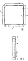
- FIG. 1 An operator control with laterally attached further control elements of various types is shown in supervision.
- 2 shows an arrangement according to FIG 1 in side view.
- 3 shows the connection of a further control element to the frame of the main control element as a detail. Another embodiment of the type of FIG. 3 is illustrated in FIG.
- the installation switch according to FIG 1 is used to issue commands for programmable building system technology. It has an operating element 1 for actuating electronic command devices and is arranged in a cover frame 3. In the area of Cover frame 3 are further small-area controls 2 trained that functional with the main control element 1 work together. The arrangement of the other controls 2 on or in frame 3 can be inserted in the manner of a slide-in technique an appropriately designed cover frame.
- the electrical connection of the other controls 2 to Main control element 1 can be located below the cover frame according to Art of foil conductors 4 according to FIG. 4.
- the electrical Connection of the other control elements 2 to the main control element 1 can also by means of contact elements 5 in a cover frame 3 take place according to FIG. Electrical commanders can be arranged on a circuit board 6 according to FIG.
- the further control elements 2 can have locks that can be unlocked by operating the main control unit 1.
- the other controls can be with a sensor surface be provided. At least one of the other controls can be pre-assigned with regard to the function. It is then ensures that the pre-assigned function by pressing of the main control element 1 is carried out. The default can be reset by means of a timer device. At least one of the other controls 2 can with a Device for wireless reception or wireless transmission be provided. By means of display devices the most varied States and functions are displayed.
Landscapes
- Engineering & Computer Science (AREA)
- Power Engineering (AREA)
- Switch Cases, Indication, And Locking (AREA)
- Power-Operated Mechanisms For Wings (AREA)
- Push-Button Switches (AREA)
- Application Of Or Painting With Fluid Materials (AREA)
- Selective Calling Equipment (AREA)
Description
In FIG 1 ist ein Bedienorgan mit seitlich angebauten weiteren Bedienelementen verschiedenartiger Ausführung in Aufsicht wiedergegeben.
In FIG 2 ist eine Anordnung nach FIG 1 in Seitenansicht dargestellt.
In FIG 3 ist der Anschluß eines weiteren Bedienelements am Rahmen des Hauptbedienorgans als Einzelheit veranschaulicht. In FIG 4 ist eine andere Ausführung nach Art von FIG 3 veranschaulicht.
Claims (10)
- Installationsschalter der programmierbaren Gebäudesystemtechnik, der mit zumindest einem Hauptbedienorgan (1) im Zusammenwirken mit zumindest einem weiteren Bedienelement (2) zur Betätigung elektrischer Befehlsgeber arbeitet,
dadurch gekennzeichnet,
daß er mit einem gesonderten Abdeckrahmen (3) nach Art der Installationstechnik versehen ist, in dessen Bereich zumindest ein weiteres kleinflächigeres Bedienelement (2) ausgebildet ist, das mit dem Hauptbedienorgan (1) funktionell zusammenarbeitet. - Installationsschalter nach Anspruch 1,
dadurch gekennzeichnet,
daß das weitere Bedienelement (2) oder die weiteren Bedienelemente (2), die auf elektrische Befehlsgeber arbeiten, elektrisch mit dem Befehlsgeber des Hauptbedienorgans (1) verbunden sind oder zu einem gemeinsamen Anschluß, insbesondere Busanschluß, geführt sind, nach Art einer Einschubtechnik an entsprechend gestalteten Abdeckrahmen (3) des Hauptbedienorgans (1) angeordnet ist. - Installationsschalter nach Anspruch 2,
dadurch gekennzeichnet,
daß die elektrische Verbindung der weiteren Bedienelemente (2) zum Hauptbedienorgan (1) unterhalb des Abdeckrahmens durch einen Folienleiter (4) erfolgt. - Installationsschalter nach Anspruch 2,
dadurch gekennzeichnet,
daß die elektrische Verbindung der weiteren Bedienelemente (2) zum Hauptbedienorgan (1) mittels Kontaktelementen (5) im Abdeckrahmen (3) erfolgt. - Installationsschalter nach Anspruch 1 oder einem der vorhergehenden Ansprüche,
dadurch gekennzeichnet,
daß die weiteren Bedienelemente (2) Sperren aufweisen, die durch Betätigen des Hauptbedienorgans (1) entsperrbar sind. - Installationsschalter nach Anspruch 1 oder einem der vorhergehenden Ansprüche,
dadurch gekennzeichnet,
daß die weiteren Bedienelemente (2) mit einer Sensorfläche versehen sind. - Installationsschalter nach Anspruch 1 oder einem der vorhergehenden Ansprüche,
dadurch gekennzeichnet,
daß zumindest eines der weiteren Bedienelemente (2) hinsichtlich der Funktion vorbelegt ist. - Installationsschalter nach Anspruch 7,
dadurch gekennzeichnet,
daß die Vorbelegung mittels einer Timereinrichtung zurücksetzbar ist. - Installationsschalter nach Anspruch 1 oder einem der vorhergehenden Ansprüche,
dadurch gekennzeichnet,
daß zumindest eines der weiteren Bedienelemente (2) mit einer Vorrichtung für drahtlosen Empfang oder drahtloses Senden ausgeführt ist. - Installationsschalter nach Anspruch 1 oder einem der vorhergehenden Ansprüche,
dadurch gekennzeichnet,
daß zumindest eines der weiteren Bedienelemente (2) mit einem Display für Anzeigen versehen ist.
Applications Claiming Priority (2)
| Application Number | Priority Date | Filing Date | Title |
|---|---|---|---|
| DE9408899U | 1994-05-31 | ||
| DE9408899U DE9408899U1 (de) | 1994-05-31 | 1994-05-31 | Installationsschalter zur Befehlsgabe |
Publications (2)
| Publication Number | Publication Date |
|---|---|
| EP0685861A1 EP0685861A1 (de) | 1995-12-06 |
| EP0685861B1 true EP0685861B1 (de) | 1999-01-13 |
Family
ID=6909308
Family Applications (1)
| Application Number | Title | Priority Date | Filing Date |
|---|---|---|---|
| EP95107756A Expired - Lifetime EP0685861B1 (de) | 1994-05-31 | 1995-05-19 | Installationsschalter zur Befehlsgabe |
Country Status (3)
| Country | Link |
|---|---|
| EP (1) | EP0685861B1 (de) |
| AT (1) | ATE175809T1 (de) |
| DE (2) | DE9408899U1 (de) |
Family Cites Families (10)
| Publication number | Priority date | Publication date | Assignee | Title |
|---|---|---|---|---|
| US3701869A (en) * | 1971-04-01 | 1972-10-31 | Gen Instrument Corp | Touch switch array panel |
| DE2334241C3 (de) * | 1973-07-05 | 1980-01-17 | Brown, Boveri & Cie Ag, 6800 Mannheim | Kombination eines bistabilen Stromstoßschalters mit einem elektrischen Tastschalter |
| GB2093274A (en) * | 1981-02-13 | 1982-08-25 | Coal Industry Patents Ltd | Electrical Keyboard Switch Devices |
| DE3418509A1 (de) * | 1984-05-18 | 1985-11-21 | Blaupunkt-Werke Gmbh, 3200 Hildesheim | Elektronisches geraet mit bedienelementen |
| US4609791A (en) * | 1984-12-20 | 1986-09-02 | Itt Corporation | Flexible diaphragm keypad and method of manufacture |
| US4866221A (en) * | 1988-06-06 | 1989-09-12 | Eaton Corporation | Remote power mirror switch assembly |
| DE59009587D1 (de) * | 1990-03-15 | 1995-10-05 | Siemens Ag | Einrichtung zur Befehlsgabe für programmierbare Gebäudesystemtechnik. |
| DE4115741A1 (de) * | 1991-05-14 | 1992-11-19 | Hartmut S Engel | Schalter |
| DE4137888A1 (de) * | 1991-11-18 | 1993-05-19 | Kostal Leopold Gmbh & Co Kg | Elektrische schalteranordnung fuer die stellantriebe von fahrzeugsitzteilen |
| DE9218404U1 (de) * | 1992-10-08 | 1994-01-27 | Siemens Ag | Bedienungskörper |
-
1994
- 1994-05-31 DE DE9408899U patent/DE9408899U1/de not_active Expired - Lifetime
-
1995
- 1995-05-19 DE DE59504780T patent/DE59504780D1/de not_active Expired - Fee Related
- 1995-05-19 EP EP95107756A patent/EP0685861B1/de not_active Expired - Lifetime
- 1995-05-19 AT AT95107756T patent/ATE175809T1/de not_active IP Right Cessation
Also Published As
| Publication number | Publication date |
|---|---|
| EP0685861A1 (de) | 1995-12-06 |
| DE9408899U1 (de) | 1994-09-08 |
| DE59504780D1 (de) | 1999-02-25 |
| ATE175809T1 (de) | 1999-01-15 |
Similar Documents
| Publication | Publication Date | Title |
|---|---|---|
| DE4440102C1 (de) | Modulare Steuerungsanlage mit integriertem Feldbusanschluß | |
| DE19801526C2 (de) | Kombinationsschaltvorrichtung | |
| DE19622256A1 (de) | Sitzkombinationsschalter | |
| EP0802471B1 (de) | Elektronische Anzeigevorrichtung mit einer Programmeingabe- und/oder Schaltvorrichtung für Schalt- und/oder Regelgeräte, insbesondere für Raumthermostatuhren | |
| DE60214672T2 (de) | Haushaltsgerät | |
| EP0853022B1 (de) | Funktionsmodul für Kraftfahrzeuge | |
| DE19706536C2 (de) | Montageanordnung für ein elektrisches Modul | |
| DE60203361T2 (de) | Elektronische Einrichtung und Steuerverfahren für elektronische Einrichtung | |
| EP1696710B1 (de) | Einbaudimmer | |
| EP1912828A1 (de) | Lenksäulenmodul | |
| DE10157434B4 (de) | Schaltungsanordnung zum Steuern elektrischer Vorrichtungen in einem Fahrzeug | |
| DE112006003312T5 (de) | Elektrischer Schalter | |
| DE10016180C2 (de) | Multifunktionsbedienelement | |
| EP0685861B1 (de) | Installationsschalter zur Befehlsgabe | |
| EP3799534B1 (de) | Funktionsmodul | |
| WO1994027196A1 (de) | Elektronisches gerät, insbesondere automatisierungsgerät | |
| DE10060981B4 (de) | Betätigungseinrichtung zum Auslösen wenigstens einer Funktion eines Kraftfahrzeugs | |
| EP0819331B1 (de) | Elektromechanische steuereinheit für verstelleinrichtungen in kraftfahrzeugen | |
| DE10031487B4 (de) | Schaltungsverbindungsanordnung in einer Fahrzeugtür | |
| DE19821302B4 (de) | Passiv-Infrarot-Bewegungsmelder | |
| EP0962122A1 (de) | Regler, insbesondere temperaturregler wie raumtemperaturregler | |
| DE3333081A1 (de) | Fernbedieneinheit zur steuerung verschiedener funktionen eines oder mehrerer geraete | |
| DE3728756C1 (en) | Switch block with a plurality of control switches, in particular for a motor vehicle | |
| EP0966826B1 (de) | Eingabevorrichtung für funkbetriebene kommunikationsendgeräte | |
| EP2043118A2 (de) | Elektrisches/elektronisches Installationsgerät |
Legal Events
| Date | Code | Title | Description |
|---|---|---|---|
| PUAI | Public reference made under article 153(3) epc to a published international application that has entered the european phase |
Free format text: ORIGINAL CODE: 0009012 |
|
| AK | Designated contracting states |
Kind code of ref document: A1 Designated state(s): AT CH DE FR IT LI |
|
| 17P | Request for examination filed |
Effective date: 19960520 |
|
| 17Q | First examination report despatched |
Effective date: 19970423 |
|
| GRAG | Despatch of communication of intention to grant |
Free format text: ORIGINAL CODE: EPIDOS AGRA |
|
| GRAG | Despatch of communication of intention to grant |
Free format text: ORIGINAL CODE: EPIDOS AGRA |
|
| GRAH | Despatch of communication of intention to grant a patent |
Free format text: ORIGINAL CODE: EPIDOS IGRA |
|
| GRAH | Despatch of communication of intention to grant a patent |
Free format text: ORIGINAL CODE: EPIDOS IGRA |
|
| GRAA | (expected) grant |
Free format text: ORIGINAL CODE: 0009210 |
|
| AK | Designated contracting states |
Kind code of ref document: B1 Designated state(s): AT CH DE FR IT LI |
|
| REF | Corresponds to: |
Ref document number: 175809 Country of ref document: AT Date of ref document: 19990115 Kind code of ref document: T |
|
| REG | Reference to a national code |
Ref country code: CH Ref legal event code: NV Representative=s name: SIEMENS SCHWEIZ AG Ref country code: CH Ref legal event code: EP |
|
| ET | Fr: translation filed | ||
| REF | Corresponds to: |
Ref document number: 59504780 Country of ref document: DE Date of ref document: 19990225 |
|
| ITF | It: translation for a ep patent filed |
Owner name: STUDIO JAUMANN P. & C. S.N.C. |
|
| PLBE | No opposition filed within time limit |
Free format text: ORIGINAL CODE: 0009261 |
|
| STAA | Information on the status of an ep patent application or granted ep patent |
Free format text: STATUS: NO OPPOSITION FILED WITHIN TIME LIMIT |
|
| 26N | No opposition filed | ||
| PGFP | Annual fee paid to national office [announced via postgrant information from national office to epo] |
Ref country code: AT Payment date: 20010411 Year of fee payment: 7 |
|
| PGFP | Annual fee paid to national office [announced via postgrant information from national office to epo] |
Ref country code: FR Payment date: 20010522 Year of fee payment: 7 |
|
| PGFP | Annual fee paid to national office [announced via postgrant information from national office to epo] |
Ref country code: DE Payment date: 20010720 Year of fee payment: 7 |
|
| PGFP | Annual fee paid to national office [announced via postgrant information from national office to epo] |
Ref country code: CH Payment date: 20010813 Year of fee payment: 7 |
|
| PG25 | Lapsed in a contracting state [announced via postgrant information from national office to epo] |
Ref country code: AT Free format text: LAPSE BECAUSE OF NON-PAYMENT OF DUE FEES Effective date: 20020519 |
|
| PG25 | Lapsed in a contracting state [announced via postgrant information from national office to epo] |
Ref country code: LI Free format text: LAPSE BECAUSE OF NON-PAYMENT OF DUE FEES Effective date: 20020531 Ref country code: CH Free format text: LAPSE BECAUSE OF NON-PAYMENT OF DUE FEES Effective date: 20020531 |
|
| PG25 | Lapsed in a contracting state [announced via postgrant information from national office to epo] |
Ref country code: DE Free format text: LAPSE BECAUSE OF NON-PAYMENT OF DUE FEES Effective date: 20021203 |
|
| REG | Reference to a national code |
Ref country code: CH Ref legal event code: PL |
|
| PG25 | Lapsed in a contracting state [announced via postgrant information from national office to epo] |
Ref country code: FR Free format text: LAPSE BECAUSE OF NON-PAYMENT OF DUE FEES Effective date: 20030131 |
|
| REG | Reference to a national code |
Ref country code: FR Ref legal event code: ST |
|
| PG25 | Lapsed in a contracting state [announced via postgrant information from national office to epo] |
Ref country code: IT Free format text: LAPSE BECAUSE OF NON-PAYMENT OF DUE FEES;WARNING: LAPSES OF ITALIAN PATENTS WITH EFFECTIVE DATE BEFORE 2007 MAY HAVE OCCURRED AT ANY TIME BEFORE 2007. THE CORRECT EFFECTIVE DATE MAY BE DIFFERENT FROM THE ONE RECORDED. Effective date: 20050519 |