EP0685664B1 - Schaltvorrichtung für ein automatisches Getriebe - Google Patents
Schaltvorrichtung für ein automatisches Getriebe Download PDFInfo
- Publication number
- EP0685664B1 EP0685664B1 EP95108062A EP95108062A EP0685664B1 EP 0685664 B1 EP0685664 B1 EP 0685664B1 EP 95108062 A EP95108062 A EP 95108062A EP 95108062 A EP95108062 A EP 95108062A EP 0685664 B1 EP0685664 B1 EP 0685664B1
- Authority
- EP
- European Patent Office
- Prior art keywords
- selector
- gate
- shift
- shift device
- selector lever
- Prior art date
- Legal status (The legal status is an assumption and is not a legal conclusion. Google has not performed a legal analysis and makes no representation as to the accuracy of the status listed.)
- Expired - Lifetime
Links
Images
Classifications
-
- F—MECHANICAL ENGINEERING; LIGHTING; HEATING; WEAPONS; BLASTING
- F16—ENGINEERING ELEMENTS AND UNITS; GENERAL MEASURES FOR PRODUCING AND MAINTAINING EFFECTIVE FUNCTIONING OF MACHINES OR INSTALLATIONS; THERMAL INSULATION IN GENERAL
- F16H—GEARING
- F16H59/00—Control inputs to control units of change-speed- or reversing-gearings for conveying rotary motion
- F16H59/02—Selector apparatus
- F16H59/0204—Selector apparatus for automatic transmissions with means for range selection and manual shifting, e.g. range selector with tiptronic
-
- B—PERFORMING OPERATIONS; TRANSPORTING
- B60—VEHICLES IN GENERAL
- B60W—CONJOINT CONTROL OF VEHICLE SUB-UNITS OF DIFFERENT TYPE OR DIFFERENT FUNCTION; CONTROL SYSTEMS SPECIALLY ADAPTED FOR HYBRID VEHICLES; ROAD VEHICLE DRIVE CONTROL SYSTEMS FOR PURPOSES NOT RELATED TO THE CONTROL OF A PARTICULAR SUB-UNIT
- B60W50/00—Details of control systems for road vehicle drive control not related to the control of a particular sub-unit, e.g. process diagnostic or vehicle driver interfaces
- B60W2050/0001—Details of the control system
- B60W2050/0043—Signal treatments, identification of variables or parameters, parameter estimation or state estimation
- B60W2050/0057—Frequency analysis, spectral techniques or transforms
-
- F—MECHANICAL ENGINEERING; LIGHTING; HEATING; WEAPONS; BLASTING
- F16—ENGINEERING ELEMENTS AND UNITS; GENERAL MEASURES FOR PRODUCING AND MAINTAINING EFFECTIVE FUNCTIONING OF MACHINES OR INSTALLATIONS; THERMAL INSULATION IN GENERAL
- F16H—GEARING
- F16H59/00—Control inputs to control units of change-speed- or reversing-gearings for conveying rotary motion
- F16H2059/006—Overriding automatic control
-
- F—MECHANICAL ENGINEERING; LIGHTING; HEATING; WEAPONS; BLASTING
- F16—ENGINEERING ELEMENTS AND UNITS; GENERAL MEASURES FOR PRODUCING AND MAINTAINING EFFECTIVE FUNCTIONING OF MACHINES OR INSTALLATIONS; THERMAL INSULATION IN GENERAL
- F16H—GEARING
- F16H59/00—Control inputs to control units of change-speed- or reversing-gearings for conveying rotary motion
- F16H59/02—Selector apparatus
- F16H59/08—Range selector apparatus
- F16H2059/082—Range selector apparatus for different transmission modes
-
- F—MECHANICAL ENGINEERING; LIGHTING; HEATING; WEAPONS; BLASTING
- F16—ENGINEERING ELEMENTS AND UNITS; GENERAL MEASURES FOR PRODUCING AND MAINTAINING EFFECTIVE FUNCTIONING OF MACHINES OR INSTALLATIONS; THERMAL INSULATION IN GENERAL
- F16H—GEARING
- F16H59/00—Control inputs to control units of change-speed- or reversing-gearings for conveying rotary motion
- F16H59/02—Selector apparatus
- F16H59/08—Range selector apparatus
- F16H2059/082—Range selector apparatus for different transmission modes
- F16H2059/084—Economy mode
-
- F—MECHANICAL ENGINEERING; LIGHTING; HEATING; WEAPONS; BLASTING
- F16—ENGINEERING ELEMENTS AND UNITS; GENERAL MEASURES FOR PRODUCING AND MAINTAINING EFFECTIVE FUNCTIONING OF MACHINES OR INSTALLATIONS; THERMAL INSULATION IN GENERAL
- F16H—GEARING
- F16H59/00—Control inputs to control units of change-speed- or reversing-gearings for conveying rotary motion
- F16H59/02—Selector apparatus
- F16H59/08—Range selector apparatus
- F16H2059/082—Range selector apparatus for different transmission modes
- F16H2059/085—Power mode
-
- F—MECHANICAL ENGINEERING; LIGHTING; HEATING; WEAPONS; BLASTING
- F16—ENGINEERING ELEMENTS AND UNITS; GENERAL MEASURES FOR PRODUCING AND MAINTAINING EFFECTIVE FUNCTIONING OF MACHINES OR INSTALLATIONS; THERMAL INSULATION IN GENERAL
- F16H—GEARING
- F16H59/00—Control inputs to control units of change-speed- or reversing-gearings for conveying rotary motion
- F16H59/02—Selector apparatus
- F16H59/08—Range selector apparatus
- F16H2059/082—Range selector apparatus for different transmission modes
- F16H2059/086—Adaptive mode, e.g. learning from the driver
-
- F—MECHANICAL ENGINEERING; LIGHTING; HEATING; WEAPONS; BLASTING
- F16—ENGINEERING ELEMENTS AND UNITS; GENERAL MEASURES FOR PRODUCING AND MAINTAINING EFFECTIVE FUNCTIONING OF MACHINES OR INSTALLATIONS; THERMAL INSULATION IN GENERAL
- F16H—GEARING
- F16H61/00—Control functions within control units of change-speed- or reversing-gearings for conveying rotary motion ; Control of exclusively fluid gearing, friction gearing, gearings with endless flexible members or other particular types of gearing
- F16H2061/0075—Control functions within control units of change-speed- or reversing-gearings for conveying rotary motion ; Control of exclusively fluid gearing, friction gearing, gearings with endless flexible members or other particular types of gearing characterised by a particular control method
- F16H2061/0081—Fuzzy logic
-
- F—MECHANICAL ENGINEERING; LIGHTING; HEATING; WEAPONS; BLASTING
- F16—ENGINEERING ELEMENTS AND UNITS; GENERAL MEASURES FOR PRODUCING AND MAINTAINING EFFECTIVE FUNCTIONING OF MACHINES OR INSTALLATIONS; THERMAL INSULATION IN GENERAL
- F16H—GEARING
- F16H61/00—Control functions within control units of change-speed- or reversing-gearings for conveying rotary motion ; Control of exclusively fluid gearing, friction gearing, gearings with endless flexible members or other particular types of gearing
- F16H2061/0075—Control functions within control units of change-speed- or reversing-gearings for conveying rotary motion ; Control of exclusively fluid gearing, friction gearing, gearings with endless flexible members or other particular types of gearing characterised by a particular control method
- F16H2061/0096—Control functions within control units of change-speed- or reversing-gearings for conveying rotary motion ; Control of exclusively fluid gearing, friction gearing, gearings with endless flexible members or other particular types of gearing characterised by a particular control method using a parameter map
-
- F—MECHANICAL ENGINEERING; LIGHTING; HEATING; WEAPONS; BLASTING
- F16—ENGINEERING ELEMENTS AND UNITS; GENERAL MEASURES FOR PRODUCING AND MAINTAINING EFFECTIVE FUNCTIONING OF MACHINES OR INSTALLATIONS; THERMAL INSULATION IN GENERAL
- F16H—GEARING
- F16H59/00—Control inputs to control units of change-speed- or reversing-gearings for conveying rotary motion
- F16H59/02—Selector apparatus
- F16H59/08—Range selector apparatus
- F16H59/10—Range selector apparatus comprising levers
Definitions
- the invention relates to a switching device for an automatic transmission of a motor vehicle, with a selector lever, which in a first shift gate between the automatic selection levels is pivotable, and with which the automatic transmission gears according to a the first driving program can be preselected and the over a cross alley into an H-shaped shift gate a switching lane and further switching lanes are transferred can to shift the gears of the transmission manually.
- a switching device for an automatic transmission has become known in which the Selector lever can be pivoted in two shift gates.
- a first shift gate are the selector positions P, R, N, D, 3, 2, 1 preselectable.
- the selector lever can have a cross alley be transferred to the second shift gate.
- By Longitudinal swiveling in this switch alley is the individual To shift gears of the transmission manually.
- a comparable one Switching device is also known from EP-B 0 331 797.
- DE 40 42 045 A1 describes a switching device for an automatic transmission for a motor vehicle known, which Guide grooves to limit the movement of the shift lever having.
- the guide grooves are in the form of an or several H schemes arranged so that the shift lever in several parallel switching lanes and in one cross lane can be moved.
- a switching device is also from the generic JP-A 61-157855 known for an automatic transmission in which the Shift gate for preselection of the automatic gears or driving programs another shifting gate assigned.
- This shift gate is H-shaped and therefore offers the same as the switching device of the aforementioned DE 40 42 045 A1 the driver that him from Manual gearbox familiar picture. For the driver this has the advantage that when changing from a vehicle with manual transmission on a vehicle with an automatic transmission has no transition problems.
- this known solutions go beyond this advantage Aggregation of a shift gate to select the automatic functions with a shift gate for manual gear selection not out.
- the present invention is based on the object a switching device for an automatic transmission type mentioned so that in the connection a shift gate to pre-select the automatic functions with a shift gate for manual gear shifting additional Synergy effects can be achieved.
- the object underlying the invention is thereby solved that in a position of the selector lever within the H-shaped shifting gate generates a signal which activates another driving program.
- This position corresponds to the area in which the Selector gate and a shift gate of the H-shaped shift gate cross.
- the proposed solution is known to the person skilled in the art the crucial hint given as a functional Fusion of a shift or selection gate for automatic functions with a switching gate for the manual functions can be done.
- the solution is therefore exhausted not in the mere aggregation of a switching or Selector lane for automatic functions and an H-shaped one Shifting gate, but allows driving in all Automatic gearbox with two gears different driving programs.
- the first driving program is advantageously a consumption-optimized driving program D_E and one performance-oriented driving program D_S as another Driving program provided.
- the activated driving program is a driving program, in which all gears with a performance-oriented driving style be available.
- the shift gate preferably connects to this shift gate so that the driving programs D_E and D_S opposite. Their spatial location is through a cross alley Cut.
- the selector lever for manual Gear shift generates a gear shift signal that from an electronic control unit for admissibility or Plausibility is checked and further processed. So there is an advantageous way of doing that Accept gear shift signal only if the selected one Gear is in a permissible speed range.
- the driver has a particularly good shift feeling convey when an accepted gear shift signal to the Driver is communicated haptically. It has proven to be very elegant proven if with an unaccepted gear shift signal the selector lever in its starting position D_S is automatically returned.
- One way to generate a haptic signal consists of locking the selector lever in the selected one Gear shift position.
- the switching device becomes a manually shifted gear when driving at low speed solved automatically.
- the selector lever is released and returned to its starting position D_S. Subsequently the driving program D_S is activated, which automatically required downshift executes.
- the driving program D_S is only activated after a predefinable time interval.
- the driving program D_S by the activated time window not called when the selector lever only the selected position D_S passes over.
- the proposed switching device can of course undergo further modifications without this the essence of the invention is left.
- the driving program that is activated when the Selector lever in a defined position within the H-shaped Shifting gate is located, according to any strategies work.
- This driving program can - at least in part - according to fuzzy logic methods, according to neural network technology, according to analytical strategies or a combination several strategies using switching points, lines and maps work.
- a first embodiment of the invention is as follows using the example of an electrohydraulically controlled automatic 4-speed gearbox with the programs "Drive_ economy, D_E "and the switch positions N (neutral), R (reverse) and P (parking) explained in more detail.
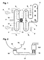
- Fig. 1 is a selector lever 1 with a circular Cross-section shown hatched. Selector lever 1 is over a pivot point, not shown, is articulated pivoted and supported by the driver in a first Weggasse 2 can be pivoted. At the first Heidelberggasse 2 is followed by an H-shaped shift gate 3.
- the automatic shift alley is the arrangement of the individual selector lever positions Automatic standard.
- This shift gate contains the shift positions P, R, N and D_E (driving program with consumption-oriented Driving style).
- the shift gate 2 can also be the usual automatic Switch positions 3, 2 and 1 can be added. Be here the possible upshifts limited or not allowed, where in position 1 the clutch for the Power transmission closed when overrun in first gear becomes.
- the selector lever 1 is from the shift gate 2 from the Switch position or program selection D_E via a cross alley 4 convertible into the H-shaped shift gate 3.
- the H-shaped shift gate 3 consists of two further switching lanes 5 and 6, which have a selector lane 7 connected together, together.
- the shift gate 3 offers the driver one of a four-speed manual transmission her usual picture.
- the Gear shift 3 if necessary around an alley for at least another gear, for example a fifth gear, be expanded.
- gear alley 5 In the shift alley 5 are the manually switchable Gears 1 and 2 and in gear alley 6 gears 3 and 4 diametrically opposite.
- the springs F their directions of action in the longitudinal direction of the switching lanes 5 and 6 are by at least added another spring F on the side, to the aforementioned starting position of the selector lever 1 in the Ensure shift gate 3.
- the direction of action of this Another spring F runs in the same direction as the direction der Wählgasse 7.
- the springs F can be tension and / or compression springs. Instead of the proposed springs equivalent elastic elements can be used be that ensure that the selector lever 1 in a certain Starting position transferred within the shift gate 3 becomes.
- the gear shift signal generated by the latching of selector lever 1 acknowledged. With the locking magnets or other suitable means will not only lock this ensured. Through this process, the driver rather, a haptic signal is also transmitted. Herewith a very good shift feeling can be realized.
- the switching device For a low-revving Driving style in a manually shifted gear the electronic control unit unlocks the Selector lever 1 triggered. Then the selector lever when falling below a lower speed limit automatically in the Starting position returned within the shift gate 3. This action can be followed by another step like below, connect.
- the arrows 10, 11, 12 and 13 shown in FIG. 1 illustrate the return of the selector lever 1 in his Starting position in the shift gate 3.
- An essential feature of the present invention now consists in the area in which the Weggasse 6 of the corridors 3 and 4 with the selection alley 7 and the Cross Quergasse 4, another function of the automatic Gearbox is assigned. In this switch position Another driving program is called. This driving program can also be automatic in itself.
- This switching position or driving program is in an area of the shift gate 3, i.e. the manual shift gate, shifted.
- This can be a functional Achieve a fusion of the automatic and manual functions, because this switching position or this driving program both from shift gate 2 and from the shift gate 3 off (here also under the given conditions automatically) can be reached.
- the starting position of the selector lever 1 mentioned several times within the shift gate 3 corresponds to this additional Switch position, so that the selector lever 1 without external influence in this starting position in the intersection area the selector lane 7 and the switching lane 6 resiliently centered is.
- the associated driving program is is a driving program in which all gears of the automatic Gearboxes are available and that on a performance-oriented (sporty) driving style is coordinated.
- the driving programs D_E (Schaltgasse 2) and D_S are located opposite, so that a driving program change always from D_E after D_S or vice versa.
- This driving program D_S can also - depending on driving behavior of the driver - can be generated adaptively.
- the switching device explained above is for of great advantage to the driver in several ways: On the one hand, there is a targeted intervention by the driver for manual Gear selection possible. The driver can take special road tours or special traffic situations intuitively and react effectively. On the other hand, there is the atypical Positioning of the additional driving program D_S in the Gear shift 3 against the driver's intentions if this from Heidelberg 2, the automatic functions is reserved, in the shift gate for manual gear selection changes: Even if the driver of the given Option of manual gear selection does not make use of is a performance-oriented driving style (which in most Cases of triggers for a desired manual Gear selection is nevertheless given. In this respect, the proposed one Solution no mere addition of a shift gate with automatic functions and an H-shaped shift gate for manual gear selection.
- Fig. 2 is a way to lock the Selector lever 1 indicated schematically.
- the selector lever 1 notches 15 and 16 are incorporated. This can be assigned to third and fourth gear, for example his.
- a two-armed angle lever 17 carries on his free end of a locking ball 18. The other end is - under Interposition of a compression spring 19 - with the locking magnet 8 or 9 connected.
- the schematically indicated locking device provides a locking or latching the selector lever 1 in one of the possible gear shift positions for sure. On the other hand, this locking is at a gear change by overcoming the force of the compression spring 19 can be suppressed.
- the shifting gate is one for five or more manually shiftable gears, it is advantageous, the proposed starting position of the selector lever 1 in the intersection of Weggasse 6 and the Maintain 7 Wahlgasse. So when you leave the shift position for fifth gear also the driving program D_S activated unless another gear is switched manually.
- a driving program is activated when the selector lever is in a specified range is located within the H-shaped shift gate 3.
- This The area can correspond to the position in which the Selective lane 7 and Wegasse 6 of the H-shaped Cross shift gate 3.
- the drive program that can be activated - at least partially - according to fuzzy logic methods, more neural Network technology, analytical strategies or one Combining Multiple Strategies Using Switching points, lines and maps can work.
Landscapes
- Engineering & Computer Science (AREA)
- General Engineering & Computer Science (AREA)
- Mechanical Engineering (AREA)
- Arrangement Or Mounting Of Control Devices For Change-Speed Gearing (AREA)
- Control Of Transmission Device (AREA)
Description
Es zeigen:
- Fig. 1
- eine schematische Ansicht einer Schaltvorrichtung mit einem Wählhebel und
- Fig. 2
- eine Einzelheit der Schaltvorrichtung nach Fig. 1 in ebenfalls stark vereinfachter, schematischer Darstellung.
- 1
- Wählhebel
- 2
- Schaltgasse
- 3
- Schaltkulisse
- 4
- Quergasse
- 5
- Schaltgasse
- 6
- Schaltgasse
- 7
- Wählgasse
- 8
- Riegelmagnet
- 9
- Riegelmagnet
- 10
- Pfeil
- 11
- Pfeil
- 12
- Pfeil
- 13
- Pfeil
- 14
- Nockenbahn
- 15
- Kerben
- 16
- Kerben
- 17
- Winkelhebel
- 18
- Rastkugel
- 19
- Druckfeder
Claims (15)
- Schaltvorrichtung für ein automatisches Getriebe eines Kraftfahrzeugs, mit einem Wählhebel (1), der in einer ersten Schaltgasse (2) zwischen den Automatik-Wahlstufen verschwenkbar ist, und mit welchem die automatisch zu schaltenden Getriebegänge gemäß einem ersten Fahrprogramm vorwählbar sind und der über eine Quergasse (4) in eine H-förmige Schaltkulisse (3) mit einer Wählgasse (7) und weiteren Schaltgassen (5, 6) überführt werden kann, um die Getriebegänge manuell zu schalten, dadurch gekennzeichnet, daß, wenn der Wählhebel (1) sich in einer Stellung befindet, in der sich die Wählgasse (7) und die Schaltgasse (6) der H-förmigen Schaltkulisse (3) kreuzen, ein Signal generiert wird, durch das ein weiteres Fahrprogramm aktiviert wird.
- Schaltvorrichtung nach Anspruch 1, dadurch gekennzeichnet, daß das erste Fahrprogramm ein verbrauchsoptimiertes Fahrprogramm D_E und das weitere Fahrprogramm ein leistungsorientiertes Fahrprogramm D_S ist.
- Schaltvorrichtung nach Anspruch 2, dadurch gekennzeichnet, daß in der ersten Schaltgasse (2) die Wählstellungen P, R, N und D_E liegen.
- Schaltvorrichtung nach den Ansprüchen 1 bis 3, dadurch gekennzeichnet, daß sich die Fahrprogramme D_E und D_S, getrennt durch die Quergasse (4) gegenüberliegen.
- Schaltvorrichtung nach Anspruch 1, dadurch gekennzeichnet, daß der Wählhebel (1) im Kreuzungsbereich der Wählgasse (7) und der Schaltgasse (6) federnd zentriert ist.
- Schaltvorrichtung nach Anspruch 2, dadurch gekennzeichnet, daß der Wählhebel (1) zur manuellen Schaltung eines Ganges ein Gangschaltsignal generiert, das von einem elektronischen Steuergerät akzeptiert wird, sofern der angewählte Gang im erlaubten Drehzahlbereich liegt.
- Schaltvorrichtung nach Anspruch 6, dadurch gekennzeichnet, daß ein akzeptiertes Gangschaltsignal dem Fahrer haptisch mitgeteilt wird, während bei einem nicht akzeptierten Gangschaltsignal der Wählhebel (1) in seine Ausgangsstellung D_S selbsttätig zurückgeführt wird.
- Schaltvorrichtung nach Anspruch 7, dadurch gekennzeichnet, daß das haptische Signal durch Verrasten des Wählhebels (1) in der angewählten Gangschaltstellung (I, II, III oder IV) generiert wird.
- Schaltvorrichtung nach Anspruch 2, dadurch gekennzeichnet, daß ein manuell geschalteter Gang bei Erreichen einer unteren Drehzahlgrenze selbsttätig dadurch gelöst wird, daß der Wählhebel (1) entrastet und in seine Ausgangsstellung D_S zurückgeführt wird und anschließend durch das aktivierte Fahrprogramm D_S eine Rückschaltung ausgeführt wird.
- Schaltvorrichtung nach Anspruch 2, dadurch gekennzeichnet, daß ein Zeitfenster aktiviert wird, wenn der Wählhebel die Wählstellung D_S erreicht, so daß das Fahrprogramm D_S nach Ablauf eines vorgebbaren Zeitintervalls aktiviert bzw. nicht aktiviert wird, wenn der Wählhebel die Wählstellung D_S lediglich überfährt.
- Schaltvorrichtung nach den Ansprüchen 1 und 2, dadurch gekennzeichnet, daß das Fahrprogramm D_S adaptiv, bzw. selbstlernend ist.
- Schaltvorrichtung nach Anspruch 8, dadurch gekennzeichnet, daß die Verrastungen des Wählhebels (1) in den Gangschaltstellungen (I bis IV) der Schaltkulisse (3) durch Handkraft außer Funktion gebracht werden können.
- Schaltvorrichtung nach Anspruch 1 gekennzeichnet durch ein automatisches Getriebe mit mehr als fünf Gängen.
- Schaltvorrichtung nach Anspruch 1 dadurch gekennzeichnet, daß die erste Schaltgasse (2) die Wählstellungen P, R, N, D, 5, 4, 3, 2 aufweist.
- Schaltvorrichtung nach den Ansprüchen 1 oder 11, oder 13, dadurch gekennzeichnet, daß das aktivierte Fahrprogramm zumindest teilweise nach Fuzzy-Logik-Methoden, neuronaler Netz-Technik, analytischer Strategien oder einer Kombination mehrerer Strategien unter Verwendung von Schaltpunkten, -linien und -kennfeldern arbeitet.
Applications Claiming Priority (2)
| Application Number | Priority Date | Filing Date | Title |
|---|---|---|---|
| DE4419212 | 1994-06-01 | ||
| DE4419212A DE4419212A1 (de) | 1994-06-01 | 1994-06-01 | Schaltvorrichtung für ein automatisches Getriebe |
Publications (3)
| Publication Number | Publication Date |
|---|---|
| EP0685664A2 EP0685664A2 (de) | 1995-12-06 |
| EP0685664A3 EP0685664A3 (de) | 1997-07-23 |
| EP0685664B1 true EP0685664B1 (de) | 2001-02-14 |
Family
ID=6519562
Family Applications (1)
| Application Number | Title | Priority Date | Filing Date |
|---|---|---|---|
| EP95108062A Expired - Lifetime EP0685664B1 (de) | 1994-06-01 | 1995-05-26 | Schaltvorrichtung für ein automatisches Getriebe |
Country Status (2)
| Country | Link |
|---|---|
| EP (1) | EP0685664B1 (de) |
| DE (2) | DE4419212A1 (de) |
Cited By (2)
| Publication number | Priority date | Publication date | Assignee | Title |
|---|---|---|---|---|
| CN101193773B (zh) * | 2005-06-09 | 2010-05-19 | Zf腓德烈斯哈芬股份公司 | 具有快速信号处理的信号处理系统 |
| EP4224038A3 (de) * | 2021-09-07 | 2024-12-25 | Toyota Jidosha Kabushiki Kaisha | Schaltvorrichtung für ein fahrzeug |
Families Citing this family (17)
| Publication number | Priority date | Publication date | Assignee | Title |
|---|---|---|---|---|
| DE19547750A1 (de) * | 1995-12-20 | 1997-06-26 | Bayerische Motoren Werke Ag | Schalteinrichtung für ein Kraftfahrzeug mit automatischem Getriebe |
| DE19637533B4 (de) * | 1996-09-14 | 2007-03-22 | Zf Friedrichshafen Ag | Elektrischer Fahrschalter |
| DE19736406B4 (de) * | 1997-08-21 | 2007-05-16 | Siemens Ag | Einrichtung zum Steuern eines automatischen Getriebes für ein Kraftfahrzeug |
| DE19744598B4 (de) * | 1997-10-09 | 2006-06-08 | Volkswagen Ag | Verfahren zum Steuern eines Automatikgetriebes eines Kraftfahrzeuges |
| DE19755096A1 (de) * | 1997-12-11 | 1999-06-17 | Volkswagen Ag | Verfahren und Steuervorrichtung zum Steuern eines Automatikgetriebes oder eines automatisierten Schaltgetriebes eines Kraftfahrzeuges |
| SE513585C2 (sv) * | 1998-06-12 | 2000-10-02 | Kongsberg Automotive Ab | Manöveranordning innefattande en manöverspak och en manöverkonsol |
| DE10059279B4 (de) * | 1999-12-08 | 2013-07-25 | Schaeffler Technologies AG & Co. KG | Kraftfahrzeug mit Getriebe |
| NO312564B1 (no) | 2000-01-25 | 2002-05-27 | Kongsberg Automotive Asa | Girskifteanordning for kjöretöyer |
| JP3792586B2 (ja) * | 2002-03-12 | 2006-07-05 | 本田技研工業株式会社 | 車両の変速操作装置 |
| EP1567625A4 (de) * | 2002-11-15 | 2006-02-08 | Stepan Co | Kerzenmischungen mit alkylestern natürlicher herkunft |
| JP4199714B2 (ja) | 2004-09-02 | 2008-12-17 | 本田技研工業株式会社 | シフト装置及びその制御方法 |
| DE102006016780A1 (de) | 2006-04-10 | 2007-10-11 | Ford Global Technologies, LLC, Dearborn | Verfahren und Vorrichtung zur Auswahl von Fahrprogrammen bei Automatikgetrieben |
| DE102008030232A1 (de) * | 2008-06-25 | 2009-12-31 | GM Global Technology Operations, Inc., Detroit | Schaltungs-Getriebe-Einheit |
| DE102008044787A1 (de) * | 2008-08-28 | 2010-03-04 | GM Global Technology Operations, Inc., Detroit | Automatisiertes Schaltgetriebeaggregat |
| DE102014017175B4 (de) * | 2014-11-20 | 2016-11-10 | Audi Ag | Verfahren und Vorrichtung zum Betreiben eines Kraftfahrzeugs |
| DE102017203848B4 (de) * | 2017-03-08 | 2024-03-14 | Bayerische Motoren Werke Aktiengesellschaft | Bedienelement für ein Fahrzeug mit Automatikgetriebe |
| CN113309850B (zh) * | 2021-05-21 | 2022-06-07 | 福建金汉科技有限公司 | 一种可靠性好的车辆换档装置 |
Family Cites Families (8)
| Publication number | Priority date | Publication date | Assignee | Title |
|---|---|---|---|---|
| JPS61157855A (ja) | 1984-12-27 | 1986-07-17 | Nissan Motor Co Ltd | 自動変速機の手動変速装置 |
| DE3717675C5 (de) | 1987-05-26 | 2005-12-15 | Bayerische Motoren Werke Ag | Schalteinrichtung für ein Kraftfahrzeug mit automatischem Getriebe |
| US5080207A (en) * | 1987-07-22 | 1992-01-14 | Zahnradfabrik Friedrichshafen Ag | Servo-assisted gear selector |
| DE3807881A1 (de) | 1988-03-10 | 1989-09-21 | Porsche Ag | Schaltvorrichtung fuer ein automatikgetriebe eines kraftfahrzeugs |
| DE3832971A1 (de) * | 1988-09-29 | 1990-04-12 | Porsche Ag | Anzeigevorrichtung fuer ein automatisches kraftfahrzeuggetriebe |
| US5179867A (en) * | 1989-12-28 | 1993-01-19 | Aisin Aw Co., Ltd. | Automatic transmission for vehicle |
| FR2664959B1 (fr) | 1990-07-17 | 1995-06-16 | Renault | Dispositif de commande manuelle de boite de vitesses automatique. |
| US5415056A (en) * | 1992-09-21 | 1995-05-16 | Toyota Jidosha Kabushiki Kaisha | Shift control system for manually shiftable automatic transmission |
-
1994
- 1994-06-01 DE DE4419212A patent/DE4419212A1/de not_active Withdrawn
-
1995
- 1995-05-26 EP EP95108062A patent/EP0685664B1/de not_active Expired - Lifetime
- 1995-05-26 DE DE59509016T patent/DE59509016D1/de not_active Expired - Fee Related
Cited By (2)
| Publication number | Priority date | Publication date | Assignee | Title |
|---|---|---|---|---|
| CN101193773B (zh) * | 2005-06-09 | 2010-05-19 | Zf腓德烈斯哈芬股份公司 | 具有快速信号处理的信号处理系统 |
| EP4224038A3 (de) * | 2021-09-07 | 2024-12-25 | Toyota Jidosha Kabushiki Kaisha | Schaltvorrichtung für ein fahrzeug |
Also Published As
| Publication number | Publication date |
|---|---|
| DE4419212A1 (de) | 1995-12-07 |
| EP0685664A2 (de) | 1995-12-06 |
| EP0685664A3 (de) | 1997-07-23 |
| DE59509016D1 (de) | 2001-03-22 |
Similar Documents
| Publication | Publication Date | Title |
|---|---|---|
| EP0444250B1 (de) | Schaltvorrichtung für ein automatisches Getriebe | |
| EP0685664A2 (de) | Schaltvorrichtung für ein automatisches Getriebe | |
| DE3000577C2 (de) | Schalteinrichtung für ein aus einem Haupt- und einem Zweibereichs-Gruppengetriebe bestehenden Zahnräder-Wechselgetriebe | |
| EP1141587B1 (de) | Schaltvorrichtung für ein elektronisch gesteuertes automatikgetriebe eines kraftfahrzeuges | |
| DE102008028619A1 (de) | Schaltvorrichtung für ein Getriebe | |
| DE3237509A1 (de) | Gangschaltung fuer ein fremdkraftbetaetigtes getriebe | |
| EP1338831A2 (de) | Getriebeschalteinrichtung | |
| DE4332265C1 (de) | Anordnung zum Steuern des Gangwechsels eines selbsttätig schaltenden Gangwechselgetriebes eines Kraftfahrzeuges | |
| DE102009039113A1 (de) | Schalteinheit für ein insbesondere elektronisch geschaltetes Getriebe eines Kraftfahrzeugs | |
| EP1199498A2 (de) | Steuervorrichtung für ein Getriebe eines Kraftfahrzeuges | |
| DE102007047120B4 (de) | Schalteinheit für ein insbesondere elektronisch geschaltetes Getriebe eines Kraftfahrzeugs | |
| DE10217614A1 (de) | Bedienelement zum Anwählen von Betriebszuständen eines Getriebes | |
| EP1801463B1 (de) | Schaltvorrichtung für ein Getriebe | |
| DE3439161A1 (de) | Getriebesteuerung | |
| DE19756034A1 (de) | Wählvorrichtung für ein Fahrzeuggetriebe | |
| EP0699853A1 (de) | Bestätigungseinrichtung zum Steuern des Gangwechsels eines Kraftfahrzeuggetriebes | |
| EP0999384A1 (de) | Schaltvorrichtung für Wechselgetriebe von Kraftfahrzeugen | |
| EP1304513B1 (de) | Schaltgetriebe mit Verriegelungseinrichtung zur Verriegelung einzelner Gänge | |
| DE3228790A1 (de) | Mechanismus fuer ein manuell schaltbares getriebe | |
| EP1611375A2 (de) | Shift by wire-schaltung mit p-position | |
| DE3337930A1 (de) | Waehlschalter in einer schaltsteuerung fuer automatgetriebe | |
| DE102004060232A1 (de) | Elektrische Schalteinrichtung für ein automatisiertes Getriebe | |
| EP0696698B1 (de) | Betätigungseinrichtung zum Steuern des Gangwechsels eines Getriebes für ein Kraftfahrzeug | |
| DE69401212T2 (de) | Bedien- und steuereinrichtung eines automatischen getriebes | |
| DE19849076A1 (de) | Wähleinrichtung für ein automatisch geschaltetes Getriebe eines Kraftfahrzeugs |
Legal Events
| Date | Code | Title | Description |
|---|---|---|---|
| PUAI | Public reference made under article 153(3) epc to a published international application that has entered the european phase |
Free format text: ORIGINAL CODE: 0009012 |
|
| AK | Designated contracting states |
Kind code of ref document: A2 Designated state(s): DE FR GB IT |
|
| GRAH | Despatch of communication of intention to grant a patent |
Free format text: ORIGINAL CODE: EPIDOS IGRA |
|
| 17P | Request for examination filed |
Effective date: 19960104 |
|
| R17P | Request for examination filed (corrected) |
Effective date: 19951219 |
|
| PUAL | Search report despatched |
Free format text: ORIGINAL CODE: 0009013 |
|
| AK | Designated contracting states |
Kind code of ref document: A3 Designated state(s): DE FR GB IT |
|
| 17Q | First examination report despatched |
Effective date: 19981207 |
|
| GRAG | Despatch of communication of intention to grant |
Free format text: ORIGINAL CODE: EPIDOS AGRA |
|
| GRAG | Despatch of communication of intention to grant |
Free format text: ORIGINAL CODE: EPIDOS AGRA |
|
| GRAH | Despatch of communication of intention to grant a patent |
Free format text: ORIGINAL CODE: EPIDOS IGRA |
|
| GRAH | Despatch of communication of intention to grant a patent |
Free format text: ORIGINAL CODE: EPIDOS IGRA |
|
| GRAA | (expected) grant |
Free format text: ORIGINAL CODE: 0009210 |
|
| AK | Designated contracting states |
Kind code of ref document: B1 Designated state(s): DE FR GB IT |
|
| PG25 | Lapsed in a contracting state [announced via postgrant information from national office to epo] |
Ref country code: IT Free format text: LAPSE BECAUSE OF FAILURE TO SUBMIT A TRANSLATION OF THE DESCRIPTION OR TO PAY THE FEE WITHIN THE PRE;WARNING: LAPSES OF ITALIAN PATENTS WITH EFFECTIVE DATE BEFORE 2007 MAY HAVE OCCURRED AT ANY TIME BEFORE 2007. THE CORRECT EFFECTIVE DATE MAY BE DIFFERENT FROM THE ONE RECORDED.SCRIBED TIME-LIMIT Effective date: 20010214 Ref country code: GB Free format text: LAPSE BECAUSE OF FAILURE TO SUBMIT A TRANSLATION OF THE DESCRIPTION OR TO PAY THE FEE WITHIN THE PRESCRIBED TIME-LIMIT Effective date: 20010214 Ref country code: FR Free format text: LAPSE BECAUSE OF FAILURE TO SUBMIT A TRANSLATION OF THE DESCRIPTION OR TO PAY THE FEE WITHIN THE PRESCRIBED TIME-LIMIT Effective date: 20010214 |
|
| REF | Corresponds to: |
Ref document number: 59509016 Country of ref document: DE Date of ref document: 20010322 |
|
| EN | Fr: translation not filed | ||
| GBV | Gb: ep patent (uk) treated as always having been void in accordance with gb section 77(7)/1977 [no translation filed] |
Effective date: 20010214 |
|
| PLBE | No opposition filed within time limit |
Free format text: ORIGINAL CODE: 0009261 |
|
| STAA | Information on the status of an ep patent application or granted ep patent |
Free format text: STATUS: NO OPPOSITION FILED WITHIN TIME LIMIT |
|
| 26N | No opposition filed | ||
| PG25 | Lapsed in a contracting state [announced via postgrant information from national office to epo] |
Ref country code: DE Free format text: LAPSE BECAUSE OF NON-PAYMENT OF DUE FEES Effective date: 20020301 |