EP0685414A1 - Transporteur hélicoidal - Google Patents
Transporteur hélicoidal Download PDFInfo
- Publication number
- EP0685414A1 EP0685414A1 EP95103906A EP95103906A EP0685414A1 EP 0685414 A1 EP0685414 A1 EP 0685414A1 EP 95103906 A EP95103906 A EP 95103906A EP 95103906 A EP95103906 A EP 95103906A EP 0685414 A1 EP0685414 A1 EP 0685414A1
- Authority
- EP
- European Patent Office
- Prior art keywords
- spiral
- conveyor according
- passage
- brush
- transport
- Prior art date
- Legal status (The legal status is an assumption and is not a legal conclusion. Google has not performed a legal analysis and makes no representation as to the accuracy of the status listed.)
- Granted
Links
Images


Classifications
-
- B—PERFORMING OPERATIONS; TRANSPORTING
- B65—CONVEYING; PACKING; STORING; HANDLING THIN OR FILAMENTARY MATERIAL
- B65G—TRANSPORT OR STORAGE DEVICES, e.g. CONVEYORS FOR LOADING OR TIPPING, SHOP CONVEYOR SYSTEMS OR PNEUMATIC TUBE CONVEYORS
- B65G33/00—Screw or rotary spiral conveyors
- B65G33/24—Details
- B65G33/26—Screws
- B65G33/265—Screws with a continuous helical surface
-
- E—FIXED CONSTRUCTIONS
- E03—WATER SUPPLY; SEWERAGE
- E03F—SEWERS; CESSPOOLS
- E03F5/00—Sewerage structures
- E03F5/14—Devices for separating liquid or solid substances from sewage, e.g. sand or sludge traps, rakes or grates
Definitions
- the invention relates to a spiral conveyor for transporting solids according to the preamble of claim 1.
- Spiral conveyors of the type mentioned here are known. They have a rotating screw conveyor, that is to say rotating about a rotational or central axis, which is designed, at least in sections, as a shaftless spiral. This rotates within a shell that extends at least over a region of the envelope of the spiral.
- Such spiral conveyors are used to transport dry, moist, wet, pasty, adhesive, dusty and / or coarse material.
- the jacket can surround the spiral of the screw more or less. It is therefore also possible to enclose the screw conveyor on all sides to avoid dust, scatter and odor problems.
- the spiral and the jacket can be made of metal, but also of plastic.
- the spiral conveyors can extend over great lengths of up to over 40 m, with diameters from less than 20 to over 2000 mm.
- the central axis of the screw conveyor can be arranged in a range from 0 ° to approximately 35 ° with respect to the horizontal. It has been found in many cases that the amount of transportable solids depends strongly on the angle of inclination. In particular at angles of inclination of more than 35 °, the solids fall back through the free interior of the shaftless spiral of the screw conveyor, so that the conveying capacity of the spiral conveyor drops to 0.
- a spiral conveyor is known from WO / 90/5100, which has a shaftless spiral with at least two spiral paths which run essentially in the form of a band along an imaginary helical line.
- a special type of spiral conveyor is used to discharge solids from a solid-liquid mixture that flows in a channel.
- channels are understood to mean a transport route for transporting the solid-liquid mixture.
- Known channels can be made of concrete, steel, stainless steel, aluminum, plastic and other suitable materials, for example.
- the spiral conveyor can be arranged on a container in which the solid-liquid mixture is contained.
- the container can serve as a collecting container, intermediate storage container, storage container or the like and can consist of any suitable material.
- the casing of such spiral conveyors is preferably permeable to the flowing liquid and designed as a sieve jacket that dips into the channel at an angle of inclination.
- spiral conveyor which has the features mentioned in claim 1. It is distinguished by the fact that the spiral passage at the front in the transport direction has a smaller distance from the central axis of the spiral than the spiral passage at the rear and that the brush is arranged in a step formed by two spiral passages on the transport side of the spiral.
- the individual spiral paths form an angle of approx. 90 ° with the rotation or central axis of the spiral. They are arranged in such a way that they form a step, the step formed by the mutually offset spiral passages, that is to say seen from the central axis of the spiral, falling towards the jacket.
- the brush arranged in the step formed by the outer spiral passages very advantageously ensures that the brush, preferably also of a spiral design, cooperating with the inside of the screen casing is arranged in a quasi-recessed manner, in that the spiral passage closest to the screen casing runs in some areas next to the brush. This arrangement ensures that the frictional resistance of the spiral brush acting on the material to be screened is significantly reduced and thus a sliding of the conveyed material on the spiral flank is facilitated.
- the brush with its side surface running in the direction of transport is aligned with a transport surface of the second outermost spiral gear which runs essentially radially to the central axis.
- the frictional resistance on the jacket surrounding the spiral acts as a counterforce.
- the formation of the continuous smooth surface now ensures that the frictional resistance of the material to be conveyed on the jacket is greater than the frictional resistance of the material being conveyed on the transport surface of the spiral. This reliably prevents the material to be conveyed from remaining on the spiral and only moving around in a circle without being conveyed by the spiral along the jacket in the conveying direction.
- a spiral conveyor is preferred in which the width of the innermost spiral passage is very small in relation to its length or height measured in the axial direction of the spiral. This results in a weight saving for the spiral without foregoing the formation of a step between the innermost and the second innermost spiral passage. This relatively long step in the axial direction results in an improvement in the conveying behavior of the spiral. Due to the small width in the radial direction of the innermost spiral passage, this essentially does not contribute to material being introduced into the spiral, while it certainly prevents the backing of transport goods that have already got into the spiral into the space between the spiral aisles.
- spiral conveyor is preferred in which the narrow side of a spiral passage facing away from the central axis forms a step which preferably slopes perpendicularly to the surface of the adjacent recessed spiral passage. This design prevents solids discharged from the spiral from being pressed against the jacket, which would lead to increased frictional forces, and possibly also to a transport jam due to jammed materials.
- the spiral conveyor in which the jacket is designed as a screen jacket and which can therefore be used to discharge solids from a solid-liquid mixture from a channel or a container.
- a spiral conveyor is characterized in that the screw conveyor can be arranged at an angle of more than 35 ° with respect to the horizontal.
- the spiral conveyor according to the invention can generally be used to transport solids. If the casing surrounding the screw conveyor is designed as a sieve casing at least over a portion of the envelope, the spiral conveyor can also serve as a sieve conveyor to remove solids from a solid-liquid mixture from a channel or a container (according to the design variants mentioned at the beginning).
- the following Explanations are based on the special form of the spiral conveyor on a channel, but this in no way means a restriction to this special form of the spiral conveyor.
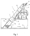
- the spiral conveyor 1 shown in FIG. 1 has a screw conveyor which is introduced into a channel 3 and which is surrounded by a screen jacket 5 in the region which projects into the channel.
- This is essentially cylindrical and, as indicated, provided with openings.
- a number and a cross section of the openings can be selected depending on the operational and operating requirements of the spiral conveyor 1.
- the openings are usually formed by round holes. Depending on the application, however, elongated holes or so-called slotted sieve bottoms can also be formed.
- the selection of the cross section of the openings is not relevant for the explanation of the invention, so that their detailed description is omitted.
- the screen jacket 5 has a plurality of substantially symmetrically arranged round holes.
- the screen jacket 5 can be formed by an essentially cylindrically shaped sheet metal part or slotted screen, which is not completely closed, but is open against the flow prevailing in the channel, indicated by an arrow.
- the solid-liquid mixture flowing in the channel can thus enter the sieve jacket through this opening, the liquid being able to escape through the openings in the sieve jacket while catch the solids there.
- These are discharged from the area of the screen jacket by a screw conveyor (not visible in FIG. 1) and conveyed further via a conical tube section 7 into a cylindrical tube area 9 and pass through this through a pressing zone 10 to an ejector 11 which opens into a suitable container 13.
- the container 13 stands outside the channel 3.
- the solids discharged from the channel 3 are increasingly compressed in the pressing zone 10.
- the water escaping is returned to the channel 3 via a drainage pipe 15.
- the spiral conveyor 1 is supported in a suitable manner by a holder 17 which is anchored outside the channel 3.
- the rotational or central axis 19 of the spiral conveyor 1 is inclined with respect to the bottom 21 of the channel 3.
- an angle of inclination ⁇ of 45 ° is realized.
- the screen jacket 5 extends to the bottom 21.
- lateral guide plates 25 are provided which extend to the lateral boundary walls of the channel 3 and ensure that all the water flows through the screen jacket 5 is directed.
- a suitable drive 27 is provided at the top, which drives the conveyor screw running inside the spiral conveyor 1 via a gear 29.
- FIG. 2 shows a section of the screw conveyor running in the interior of the spiral conveyor 1, specifically the area that is located in the interior of the screen jacket 5 (see FIG. 1) and is designed as a spiral 31.
- the spiral 31 is formed here, that is to say in the region of the screen jacket 5, as a shaftless spiral 31. Its outer diameter is selected so that it touches the screen jacket 5 on its inner surface.
- the spiral 31 has at least two, here for example four mutually stepped spiral paths 33, 35, 37 and 39, which are essentially band-shaped. Since the spiral 31, which is shown in a view in FIG.
- spiral gears 33 to 39 are arranged so that each of their broad sides shown in the sectional view encloses approximately a right angle with the central axis 19.
- the individual spiral paths 33 to 39 are arranged along an imaginary helix, so that the spiral 31 of the screw conveyor results.
- the outside diameter of the individual spiral gears is not the same.
- the spiral gear 33 with the smallest outside diameter lies on the inside of the closest spiral passage 35 so that these spiral passages overlap in regions.
- the outside diameter of the spiral passage 35 is somewhat larger than the inside diameter of the spiral passage 37, so that these two spiral passages also overlap in regions.
- the outside diameter of the spiral passage 37 is correspondingly somewhat larger than the inside diameter of the spiral passage 39, so that here too there is an overlap of the two spiral passages.
- the outer diameter of the individual spiral gears 33 to 39 is constant over the entire longitudinal extent of the spiral 31, as seen in the direction of the central axis 19, so that there is a cylindrical envelope for each individual spiral gear 33 to 39 when the spiral 31 rotates about the central axis 19 , wherein the outer diameter of the outermost spiral passage 39 is slightly smaller than the inner diameter of the screen jacket 5.
- the foremost spiral passage 33 as seen in the direction of the conveying direction, therefore has a smaller distance from the central axis 19 than the recessed next spiral passage 35.
- the steps 41 to 45 thus reliably prevent materials from escaping into the inner free space of the spiral 31.
- quasi conveyor pockets are formed, which ensure an improved discharge of the solids from the channel 3, even when the spiral conveyor 1 is inserted with an installation angle of more than 35 ° into a channel 3.
- the individual spiral ducts 33 to 39 have a simple structure, so that the spiral 31 can be produced inexpensively.
- a brush 47 which interacts with the inner surface of the screen jacket 5 and serves to clean the screen jacket 5, projects over the outer circumference of the outermost spiral passage 39.
- the brush 47 protrudes above Spiral 31 is not free, rather it is covered in regions by the outermost spiral passage 39.
- the brush 47 is thus arranged in the area of the last step 45 between the outermost spiral gear 39 and the second outermost spiral gear 37 - as will be explained in more detail with reference to FIG.
- the material discharged from the channel 3 by the spiral 31 can therefore reach the outermost spiral circumference during the circulation of the spiral 31 in the screen jacket 5.
- the frictional resistance of the spiral 31 or the spiral brush 47 which also acts on the solids also known as screenings, is significantly reduced, so that sliding of the conveyed material on the spiral flank is facilitated.
- the individual elements that is to say the spiral passages 33 to 39, from which the spiral 31 is composed, are of very simple design. Band-shaped materials that run along an imaginary helix are preferably used here.
- the connection of the individual spiral gears 33 to 39 is very simple possible, for example by conventional welding processes in which the spiral passages 33 to 39 are welded to one another along their underlying edges or else in a spot welding process. It is ensured by the spiral 31 that the spiral conveyor 1 can be inserted at a steeper angle into a channel 3 without the material 31 discharged from the spiral 31 in the area of the screen jacket 5 falling back through the free interior of the shaftless spiral 31, thereby increasing the efficiency of the spiral conveyor 1 is at least reduced, possibly even reduced to zero.
- the radial, that is, perpendicular to the central axis 19 measured width of the individual spiral passages 33 to 39 can be varied in order to arrange the steps 41, 43 and 45 on the solids to be discharged, but also, for example, on the total -Adjust the outer diameter of the spiral 31. It was assumed above that the spiral gears 33 to 39 are made of metal. Of course, for the transport of appropriate materials and with a selection of suitable substances, it is also possible to manufacture the individual spiral passages 33 to 39 from plastic.
- FIGS. 3, 4 and 5 embodiments of the spiral are explained on the basis of schematic diagrams, in which a different type of overlap is given, as shown in FIG. 1. This is because in the transition area between each two adjacent spiral paths, which are designed in the form of a band, the central plane of these spiral paths being perpendicular to the central axis of the spiral, spiral paths are used, the central plane of which runs parallel to the central axis 19.
- the brush 47 has not been shown here, but it is clear that this is in the respective of the two outer spiral gears trained stage is arranged.
- the outermost spiral passage 139 is again arranged in a partial overlap with respect to the middle spiral passage 137, as has already been explained with reference to FIG. 2.
- the height of step 41 can be increased by the quasi-vertical spiral gear 135.
- a further embodiment of the spiral results from FIG. 5, in which a quasi vertical spiral duct 135 is provided between the spiral ducts 133 and 137, the narrow sides of the spiral ducts 133 and 137 being attached to the side surfaces running in the direction of the central axis 19.
- An outer spiral passage 139 in turn adjoins radially outward.
- step 41 is formed by the quasi-vertical spiral passage 135, which has already been discussed in more detail with reference to FIG. 2.
- the spiral can also be produced from individual spiral paths that have no overlap.
- the spiral passages touching at their edges can be connected to one another in a suitable manner, for example welded.
- stabilizing elements are attached to the back of the spiral facing away from the transported solids at more or less large intervals.
- this is also possible in the exemplary embodiments explained with reference to FIGS. 2 to 5.
- FIG. 6 shows three adjacent spiral paths 133, 137 and 139, the two inner spiral paths 133 and 137 having approximately the same width and thickness, while the spiral path 139 - seen from the central axis 19 - is narrower and thinner.
- the spiral passages touch each other in their edge regions, since the outside diameter of the spiral passage 133 is as large as the inside diameter of the spiral passage 137 and the outside diameter of the spiral passage 137 is the same size as the inside diameter of the spiral passage 139.
- the height of the step 41 is determined by the thickness of the spiral passage 133.
- a quasi-vertical spiral duct 135 can be introduced between the innermost spiral duct 133 and the further spiral duct 137, the spiral ducts 133 and 137 each with only one Edge touched.
- a spiral path 139 which touches the spiral path 137 which adjoins the inside with its edge.
- FIGS. 3 to 7 are intended to make it clear that the structure of the spiral can be varied within a wide range without the basic principle being abandoned.
- the choice of the width and thickness of the individual spiral passages is adapted to the desired circumstances.
- FIG. 8 shows a sectional illustration of the spiral 31 according to a particularly preferred exemplary embodiment.
- the same parts as in Figure 2 are provided with the same reference numerals in spite of a partially different structure in order to clarify the idea of the invention.
- the spiral 31 has a total of four spiral paths 33 to 39.
- the innermost spiral passage 33 that is to say the spiral passage 33 facing the indicated central axis 19, is designed as a web 49 running in the axial direction of the spiral 31.
- the web 49 has a narrow width in relation to its axial length or height.
- the spiral passage 35 lies with its surface facing the central axis 19 on the surface of the spiral passage 33 facing the screen jacket.
- a weld 51 indicated here can give the necessary mechanical hold between the spiral gears 33 and 35.
- the spiral passages 35 and 37 touch - as in FIG. 2 - on surfaces running radially to the central axis 19, the front surface of the spiral passage 37 in the transport direction partially covering the surface of the spiral passage 35 directed counter to the transport direction.
- a weld seam 51 is again provided for connection and stabilization.
- the spiral passage 39 lies with its surface facing the central axis 19 in regions on the surface of the spiral passage 37 facing the screen jacket.
- a connection can in turn be stabilized by a weld seam 51.
- a step 53 is formed, within which the brush 47 is arranged.
- the brush 47 has a brush base 55 in which the bristles 57, which are only schematically indicated here, are locked.
- the bristles 57 here run essentially parallel to the surface of the outermost spiral passage 39.
- the base body 55 is also designed in the form of a band and follows the spiral line predetermined by the spiral passages 37 and 39, respectively.
- the essentially U-shaped basic body 55 has an approximately square cross-section, the surface 58 lying at the front in the conveying direction being aligned with the surface 59 of the spiral passage 37 lying at the front in the conveying direction. That is, the surfaces 58 and 59 form a practically continuous, smooth, flat surface.
- the essentially square cross section of the base body 55 is only ideally assumed here. For manufacturing reasons, it may be possible that the legs of the U-shaped base body 55 that clamp the bristles 57 are folded over, that is, point slightly inwards in the direction of the bristles 57. The result of this is that the surface 58 of the base body 55 lying at the front in the conveying direction drops slightly in the direction of the screen jacket relative to the surface 59.
- a clamping device 61 which has at least one clamping element 65 designed as a holding clip 63. Viewed over the spiral line of the spiral 31, a sufficiently large number of clamping devices 61 are provided at a distance from one another, which ensure a secure locking of the brush 47.
- the holding clip 63 which overlaps the surface 58 of the base body 55, the base body 55 is pressed against the spiral gear 39, so that the latter is immovable between the spiral gear 39 and the holding clip 63 is clamped.
- a clamping element 67 which applies the clamping force, is provided for tensioning the holding clip 63.
- This is designed, for example, as a clamping screw 69 which passes through a corresponding through opening of the holding clip 63 and the spiral passage 37.
- the clamping screw 69 is fixed here by means of a nut 71.
- the clamping screw 69 has a countersunk head which is arranged sunk in a corresponding recess in the holding clip 63.
- the holding clip 63 also has rounded edges which prevent the transport goods transported with the spiral 31 from getting caught.
- the entire clamping device 61 can be arranged recessed in a corresponding recess in the spiral passage 37 and the base body 55, so that there is a smooth plane of the transport surfaces formed by the surfaces 58 and 59, respectively. Finally, it is possible to attach the brush 47 directly to the spiral 39 by means of a screw penetrating the base body 55.
- the surface 58 is set back slightly from the surface 59 or is arranged slightly protruding. This leads to an additional sloping or slightly rising step. This additional step results from the fact that the axial extent of the base body 55 is smaller or larger than the axial extent of the step 53.
- the surface of the spiral passages serving the solids is arranged perpendicular to the central axis 19, while the steps formed by two adjacent spiral passages are in turn perpendicular to the side surfaces of the spiral passages and thus run parallel to the central axis 19. It is therefore impossible for the steps between the individual spiral ducts to exert radially outward compressive forces on the solids to be transported, so that the friction losses are minimal and seizing of the spiral can be excluded with a high degree of certainty.
- the number, width and height of the individual spiral ducts can be adapted to the particular design of the screw conveyor, the inner diameter of the free space of the shaftless spiral and the outer diameter of the screw conveyor playing a role.
Applications Claiming Priority (2)
| Application Number | Priority Date | Filing Date | Title |
|---|---|---|---|
| DE4419612A DE4419612A1 (de) | 1994-06-03 | 1994-06-03 | Spiralförderer |
| DE4419612 | 1994-06-03 |
Publications (2)
| Publication Number | Publication Date |
|---|---|
| EP0685414A1 true EP0685414A1 (fr) | 1995-12-06 |
| EP0685414B1 EP0685414B1 (fr) | 1997-10-22 |
Family
ID=6519829
Family Applications (1)
| Application Number | Title | Priority Date | Filing Date |
|---|---|---|---|
| EP95103906A Expired - Lifetime EP0685414B1 (fr) | 1994-06-03 | 1995-03-17 | Transporteur hélicoidal |
Country Status (5)
| Country | Link |
|---|---|
| US (1) | US5573660A (fr) |
| EP (1) | EP0685414B1 (fr) |
| AT (1) | ATE159499T1 (fr) |
| DE (2) | DE4419612A1 (fr) |
| HU (1) | HUT70823A (fr) |
Families Citing this family (13)
| Publication number | Priority date | Publication date | Assignee | Title |
|---|---|---|---|---|
| US6029290A (en) * | 1998-10-26 | 2000-02-29 | Skimmer Valet, Inc. | Swimming pool skimmer cleaner |
| US6182817B1 (en) * | 1998-11-30 | 2001-02-06 | Maumee Research & Engineering, Inc. | Field replaceable helical flight |
| AU2003900362A0 (en) * | 2003-01-29 | 2003-02-13 | Wm Olds And Sons Pty Ltd | Screw conveyor |
| US6915896B2 (en) * | 2003-02-25 | 2005-07-12 | Dippin' Dots, Inc. | Cleaning drain apparatus for an auger assembly |
| US7137503B2 (en) * | 2004-03-12 | 2006-11-21 | Emerson Electric Co. | Auger brush |
| DE102010013186B4 (de) * | 2010-03-26 | 2017-02-09 | Johann Schweiger | Reinigungsvorrichtung und Reinigungsverfahren zur Reinigung von Gewässern sowie technische Anlage mit solcher Reinigungsvorrichtung |
| US10214362B2 (en) | 2011-04-19 | 2019-02-26 | Cnh Industrial America Llc | Grain unloading system |
| AT511826B1 (de) * | 2011-11-08 | 2013-03-15 | Wildfellner Ges M B H | Befülleinrichtung für schüttgut |
| AT12361U3 (de) * | 2011-11-08 | 2013-01-15 | Wildfellner Ges M B H | Befülleinrichtung für schüttgut |
| AT13133U1 (de) * | 2012-02-23 | 2013-07-15 | Wildfellner Ges M B H | Befülleinrichtung für Schüttgut |
| US9346626B1 (en) * | 2014-12-10 | 2016-05-24 | Mohammad Fakhrizadeh | Screw conveyor |
| EP3581756A1 (fr) | 2018-06-11 | 2019-12-18 | HILTI Aktiengesellschaft | Dispositif de forage |
| CN113003118B (zh) * | 2021-03-15 | 2022-06-07 | 长兴悍将环保机械制造有限公司 | 一种用于城市垃圾处理的无轴螺旋输送机 |
Citations (5)
| Publication number | Priority date | Publication date | Assignee | Title |
|---|---|---|---|---|
| DE2115791A1 (de) * | 1971-04-01 | 1972-10-12 | Schmidt, Fritz R., Dr.-Ing., 1000 Berlin | Förderschnecke |
| DE2628015A1 (de) * | 1975-07-01 | 1977-01-27 | Immanuel Straub | Wendelflaechenfoermiges maschinenteil |
| WO1990005100A1 (fr) * | 1988-11-10 | 1990-05-17 | Spirac Engineering Ab | Transporteur helicoidal |
| DE3915529A1 (de) * | 1989-05-12 | 1990-11-15 | Noggerath & Co | Vorrichtung zum entfernen von rechen- und/oder siebgut aus einem gerinne stroemender fluessigkeiten |
| DE3915528C1 (en) * | 1989-05-12 | 1990-12-13 | Noggerath & Co, 3061 Ahnsen, De | Screw conveyor with material moisture reduction - has spiral brush in grate region, matching pitch of conveyor screw |
Family Cites Families (11)
| Publication number | Priority date | Publication date | Assignee | Title |
|---|---|---|---|---|
| US2665796A (en) * | 1949-11-19 | 1954-01-12 | James E Axeman | Coal feed tube |
| US3688687A (en) * | 1970-11-16 | 1972-09-05 | Wascon Systems Inc | Press |
| US3695173A (en) * | 1972-01-28 | 1972-10-03 | Clyde Harold Cox | Sludge dewatering |
| US4424129A (en) * | 1982-06-28 | 1984-01-03 | Bunger Richard E | Dewatering apparatus for waste recovery systems |
| WO1988009301A1 (fr) * | 1987-05-19 | 1988-12-01 | Spirac Engineering Ab | Dispositif de transport |
| SE450104B (sv) * | 1985-10-18 | 1987-06-09 | Spirac Engineering Ab | Anordning for komprimering av material och reduktion av dess vetskeinnehall |
| DE3716434C1 (de) * | 1987-05-16 | 1988-12-08 | Hans-Georg Huber | Vorrichtung zum Entfernen von Rechen- und/oder Siebgut aus in einem Gerinne stroemender Fluessigkeit |
| SE460399B (sv) * | 1988-02-29 | 1989-10-09 | Spirac Engineering Ab | Saett och anordning foer rening av ett vaetskefloede medelst ett silgaller med rengoeringsanordning |
| SE462681B (sv) * | 1988-02-29 | 1990-08-13 | Spirac Engineering Ab | Foerflyttningsanordning |
| DE4136401A1 (de) * | 1990-11-05 | 1993-01-21 | Branko Klasnic | Geraet fuer die mechanische reinigung von schmutzbehafteten fluessigkeiten |
| US5421251A (en) * | 1991-11-19 | 1995-06-06 | Spirac Engineering Ab | Apparatus for compacting material |
-
1994
- 1994-06-03 DE DE4419612A patent/DE4419612A1/de not_active Withdrawn
-
1995
- 1995-03-17 AT AT95103906T patent/ATE159499T1/de active
- 1995-03-17 DE DE59500834T patent/DE59500834D1/de not_active Expired - Fee Related
- 1995-03-17 EP EP95103906A patent/EP0685414B1/fr not_active Expired - Lifetime
- 1995-06-01 US US08/457,071 patent/US5573660A/en not_active Expired - Fee Related
- 1995-06-02 HU HU9501630A patent/HUT70823A/hu unknown
Patent Citations (5)
| Publication number | Priority date | Publication date | Assignee | Title |
|---|---|---|---|---|
| DE2115791A1 (de) * | 1971-04-01 | 1972-10-12 | Schmidt, Fritz R., Dr.-Ing., 1000 Berlin | Förderschnecke |
| DE2628015A1 (de) * | 1975-07-01 | 1977-01-27 | Immanuel Straub | Wendelflaechenfoermiges maschinenteil |
| WO1990005100A1 (fr) * | 1988-11-10 | 1990-05-17 | Spirac Engineering Ab | Transporteur helicoidal |
| DE3915529A1 (de) * | 1989-05-12 | 1990-11-15 | Noggerath & Co | Vorrichtung zum entfernen von rechen- und/oder siebgut aus einem gerinne stroemender fluessigkeiten |
| DE3915528C1 (en) * | 1989-05-12 | 1990-12-13 | Noggerath & Co, 3061 Ahnsen, De | Screw conveyor with material moisture reduction - has spiral brush in grate region, matching pitch of conveyor screw |
Also Published As
| Publication number | Publication date |
|---|---|
| ATE159499T1 (de) | 1997-11-15 |
| HUT70823A (en) | 1995-11-28 |
| DE4419612A1 (de) | 1995-12-07 |
| HU9501630D0 (en) | 1995-07-28 |
| US5573660A (en) | 1996-11-12 |
| DE59500834D1 (de) | 1997-11-27 |
| EP0685414B1 (fr) | 1997-10-22 |
Similar Documents
| Publication | Publication Date | Title |
|---|---|---|
| EP0685414B1 (fr) | Transporteur hélicoidal | |
| EP0389789B1 (fr) | Dispositif pour extraire des déchets d'un liquide courant dans un égout | |
| DE3122052C2 (de) | Zyklonseparator zum Abtrennen oder Sammeln von Festkörperpartikeln aus einem Fluid | |
| DE2362674A1 (de) | Vorrichtung zum abtrennen der festen und der fluessigen bestandteile aus einer schlamm fuehrenden fluessigkeit | |
| DE1294935B (de) | Abscheider fuer mitgefuehrte Fluessigkeitstropfen aus einem Gasstrom | |
| DE2030618B2 (de) | Schrägklärer | |
| EP2065173B1 (fr) | Surface d'arbre de vis sans fin | |
| DE69730619T2 (de) | Siebvorrichtung | |
| WO2008145079A1 (fr) | Séparateur à vis à pression | |
| EP1382554B1 (fr) | Installation de transport pneumatique ou hydraulique de matériaux en vrac | |
| DE60318833T2 (de) | Dekantierzentrifuge | |
| CH681617A5 (fr) | ||
| EP2605864A2 (fr) | Dispositif de tri | |
| WO2001012298A1 (fr) | Dispositif destine a separer des particules d'un fluide | |
| DE3216473C1 (de) | Vorrichtung zur Herstellung von Brucheis | |
| DE3616554C2 (de) | Messerwalzen-Abstreifvorrichtung für Aktenvernichter oder dgl. | |
| DE4138825C2 (de) | Vorrichtung zum Entfernen von Rechen- und/oder Siebgut aus in einem Gerinne strömender Flüssigkeit | |
| DE3830618C2 (de) | Reaktor zum Reinigen von Industrieabgasen | |
| DE3915528C1 (en) | Screw conveyor with material moisture reduction - has spiral brush in grate region, matching pitch of conveyor screw | |
| DE3920196A1 (de) | Vorrichtung zum entfernen von rechen- und/oder siebgut aus in einem gerinne stroemender fluessigkeit | |
| DE3033423C2 (de) | Blatt für Scheibenfilter | |
| CH628570A5 (de) | Plastifiziermaschine zur verarbeitung bandfoermigen rohmaterials. | |
| DE3105732C2 (de) | Schrämwalze für eine Gewinnungsmaschine des Untertagebergbaus | |
| AT400853B (de) | Sieb für papierzellstoff-splitterfänger und klassierer | |
| WO2001085298A1 (fr) | Procede et dispositif pour separer par sedimentation des particules detectables physiquement, contenues dans un flux de particules |
Legal Events
| Date | Code | Title | Description |
|---|---|---|---|
| PUAI | Public reference made under article 153(3) epc to a published international application that has entered the european phase |
Free format text: ORIGINAL CODE: 0009012 |
|
| AK | Designated contracting states |
Kind code of ref document: A1 Designated state(s): AT BE CH DE DK ES FR GB IT LI NL SE |
|
| 17P | Request for examination filed |
Effective date: 19951104 |
|
| 17Q | First examination report despatched |
Effective date: 19960906 |
|
| GRAG | Despatch of communication of intention to grant |
Free format text: ORIGINAL CODE: EPIDOS AGRA |
|
| GRAH | Despatch of communication of intention to grant a patent |
Free format text: ORIGINAL CODE: EPIDOS IGRA |
|
| GRAH | Despatch of communication of intention to grant a patent |
Free format text: ORIGINAL CODE: EPIDOS IGRA |
|
| GRAA | (expected) grant |
Free format text: ORIGINAL CODE: 0009210 |
|
| AK | Designated contracting states |
Kind code of ref document: B1 Designated state(s): AT BE CH DE DK ES FR GB IT LI NL SE |
|
| PG25 | Lapsed in a contracting state [announced via postgrant information from national office to epo] |
Ref country code: NL Free format text: LAPSE BECAUSE OF FAILURE TO SUBMIT A TRANSLATION OF THE DESCRIPTION OR TO PAY THE FEE WITHIN THE PRESCRIBED TIME-LIMIT Effective date: 19971022 Ref country code: IT Free format text: LAPSE BECAUSE OF FAILURE TO SUBMIT A TRANSLATION OF THE DESCRIPTION OR TO PAY THE FEE WITHIN THE PRESCRIBED TIME-LIMIT;WARNING: LAPSES OF ITALIAN PATENTS WITH EFFECTIVE DATE BEFORE 2007 MAY HAVE OCCURRED AT ANY TIME BEFORE 2007. THE CORRECT EFFECTIVE DATE MAY BE DIFFERENT FROM THE ONE RECORDED. Effective date: 19971022 Ref country code: GB Free format text: LAPSE BECAUSE OF FAILURE TO SUBMIT A TRANSLATION OF THE DESCRIPTION OR TO PAY THE FEE WITHIN THE PRESCRIBED TIME-LIMIT Effective date: 19971022 Ref country code: FR Free format text: LAPSE BECAUSE OF FAILURE TO SUBMIT A TRANSLATION OF THE DESCRIPTION OR TO PAY THE FEE WITHIN THE PRESCRIBED TIME-LIMIT Effective date: 19971022 Ref country code: ES Free format text: THE PATENT HAS BEEN ANNULLED BY A DECISION OF A NATIONAL AUTHORITY Effective date: 19971022 Ref country code: DK Free format text: LAPSE BECAUSE OF NON-PAYMENT OF DUE FEES Effective date: 19971022 |
|
| REF | Corresponds to: |
Ref document number: 159499 Country of ref document: AT Date of ref document: 19971115 Kind code of ref document: T |
|
| REG | Reference to a national code |
Ref country code: CH Ref legal event code: EP |
|
| REF | Corresponds to: |
Ref document number: 59500834 Country of ref document: DE Date of ref document: 19971127 |
|
| REG | Reference to a national code |
Ref country code: CH Ref legal event code: NV Representative=s name: TROESCH SCHEIDEGGER WERNER AG |
|
| PG25 | Lapsed in a contracting state [announced via postgrant information from national office to epo] |
Ref country code: SE Effective date: 19980122 |
|
| PG25 | Lapsed in a contracting state [announced via postgrant information from national office to epo] |
Ref country code: AT Free format text: LAPSE BECAUSE OF NON-PAYMENT OF DUE FEES Effective date: 19980317 |
|
| EN | Fr: translation not filed | ||
| PG25 | Lapsed in a contracting state [announced via postgrant information from national office to epo] |
Ref country code: BE Free format text: LAPSE BECAUSE OF NON-PAYMENT OF DUE FEES Effective date: 19980331 |
|
| NLV1 | Nl: lapsed or annulled due to failure to fulfill the requirements of art. 29p and 29m of the patents act | ||
| GBV | Gb: ep patent (uk) treated as always having been void in accordance with gb section 77(7)/1977 [no translation filed] |
Effective date: 19971022 |
|
| PLBE | No opposition filed within time limit |
Free format text: ORIGINAL CODE: 0009261 |
|
| STAA | Information on the status of an ep patent application or granted ep patent |
Free format text: STATUS: NO OPPOSITION FILED WITHIN TIME LIMIT |
|
| BERE | Be: lapsed |
Owner name: NOGGERATH HOLDING G.M.B.H. & CO. K.G. Effective date: 19980331 |
|
| 26N | No opposition filed | ||
| PG25 | Lapsed in a contracting state [announced via postgrant information from national office to epo] |
Ref country code: LI Free format text: LAPSE BECAUSE OF NON-PAYMENT OF DUE FEES Effective date: 19990331 Ref country code: CH Free format text: LAPSE BECAUSE OF NON-PAYMENT OF DUE FEES Effective date: 19990331 |
|
| REG | Reference to a national code |
Ref country code: CH Ref legal event code: PL |
|
| PGFP | Annual fee paid to national office [announced via postgrant information from national office to epo] |
Ref country code: DE Payment date: 20050324 Year of fee payment: 11 |
|
| PG25 | Lapsed in a contracting state [announced via postgrant information from national office to epo] |
Ref country code: DE Free format text: LAPSE BECAUSE OF NON-PAYMENT OF DUE FEES Effective date: 20061003 |