EP0685337A2 - Dispositif pour régler la surface d'appui des pinces d'un ensemble à pinces pour feuilles dans un cylindre de retournement d'une machine d'impression recto-verso - Google Patents
Dispositif pour régler la surface d'appui des pinces d'un ensemble à pinces pour feuilles dans un cylindre de retournement d'une machine d'impression recto-verso Download PDFInfo
- Publication number
- EP0685337A2 EP0685337A2 EP95105578A EP95105578A EP0685337A2 EP 0685337 A2 EP0685337 A2 EP 0685337A2 EP 95105578 A EP95105578 A EP 95105578A EP 95105578 A EP95105578 A EP 95105578A EP 0685337 A2 EP0685337 A2 EP 0685337A2
- Authority
- EP
- European Patent Office
- Prior art keywords
- gripper
- adjusting
- bar
- grippers
- turning drum
- Prior art date
- Legal status (The legal status is an assumption and is not a legal conclusion. Google has not performed a legal analysis and makes no representation as to the accuracy of the status listed.)
- Granted
Links
Images



Classifications
-
- B—PERFORMING OPERATIONS; TRANSPORTING
- B41—PRINTING; LINING MACHINES; TYPEWRITERS; STAMPS
- B41F—PRINTING MACHINES OR PRESSES
- B41F21/00—Devices for conveying sheets through printing apparatus or machines
- B41F21/10—Combinations of transfer drums and grippers
- B41F21/106—Combinations of transfer drums and grippers for reversing sheets, e.g. for perfecting machine
Definitions
- the invention relates to a device for height adjustment of the gripper bar for sheet grippers in a turning drum of a perfecting machine.
- a device of this type is known from DE 3 508 699 C2.
- the gripper pads can then be adjusted in height by means of an actuating shaft integrated in the swivel shaft using multi-stage setting levels.
- This version is structurally complex and requires a larger space.
- the object of the invention is to carry out the gripper pads for sheet grippers in a reversing drum of a perfecting machine, depending on the printing material thickness to be processed, in a height-adjustable manner with minimal space requirement, in a compact design with appropriate register stability.
- the invention is suitable for turning drums in which the space available for adjusting the gripper pads is limited. With the present solution, the assembly effort is reduced and the gripper supports are adjusted continuously or in steps plane-parallel to the swivel shaft. Another advantage is the higher rigidity of the adjusting device, which is formed from a thrust cam mechanism, and the improvement of the plane parallelism of the gripper supports to the swivel shaft. The present solution reduces the mass forces, which is a further advantage with pivoting bearing plates.
- the invention is suitable for gripper pad adjustment for straight printing as well as for counterpressure grippers.
- a sheet-fed offset printing machine is shown in series.
- a double-sized turning drum 18 is arranged between two double-sized printing cylinders 17.
- a rubber blanket cylinder 19 and a plate cylinder 20 are associated with each printing cylinder 17 in a known manner.
- the turning drum 18 carries on each half a gripping device 21, which is formed by a suction system 22, a first gripper system 23 (counter pressure gripper) and a second gripper system 24 (fine pressure gripper) (FIG. 5).
- a height-adjustable gripper bar 4 of the second gripper system 24 is to be explained in more detail.
- the first gripper system 23 can be designed analogously.
- a pivot shaft 1 is rotatably fixed to the turning drum 18 in a plurality of bearing blocks 25 arranged transversely to the sheet running direction.
- the pivot shaft 1 carries a plurality of holding plates 2 arranged at a uniform distance, in which a gripper shaft 16 is mounted.
- Each holding plate 2 has a groove 3 aligned in approximately radial direction (with respect to the turning drum 18) axially parallel to the pivot shaft 1.
- the gripper bar 4 which runs axially parallel to the turning drum 18 or the pivot shaft 1, is accommodated in each groove 3.
- the height adjustment is integrated in a groove 7 in the gripper bar 4.
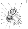
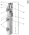
- the height adjustment consists of a flat thrust cam mechanism, which is formed in Fig. 1 and 3 from a fixed wedge 6 and a pull bar 8 and represents the adjusting device.
- Each wedge 6 is fixed in the groove 3 on the holding plate 2.
- the pull bar 8 represents the cam carrier and runs parallel to the gripper bar 4.
- Each cam joint is thus formed by the wedge 6 and the associated curve of the pull bar 8.
- the gripper bar 4 is designed in two parts, such that a part is detachably connected to the holding plate 2 with a connecting element 10, for example a screw.
- a connecting element 10 for example a screw.
- On the first part of the gripper bar 4 a compression spring 9 is arranged, which is received on the second part of the gripper bar 4. Due to the spring force, the positive movement is guaranteed on each cam joint.
- a number of gripper supports are arranged on the gripper bar 4 at defined intervals and are assigned to the respective gripper of a row of grippers (not shown) on the gripper shaft 16.
- each cam joint of the thrust cam mechanism is formed according to FIG. 2 by the fixed wedge 6 and an associated roller 12, which is rotatably mounted on a pin 11 fixed to the gripper bar 4.
- a threaded bolt 13 is fastened on the end face of the drawing strip 8 and forms a screw gear with a threaded sleeve 26.
- the threaded bolt 13 has a handle 14 at its free end, which is preferably designed as a knurled handle.
- the screw gear is guided in a bush 15.
- the mode of operation is as follows: If substrates with different thicknesses (paper, cardboard) are to be processed, the height of the gripper bar 4 must be adjusted. When processing relatively thick substrates, the gripper bar 4 is set lower; when processing relatively thin substrates, the gripper bar 4 is raised.
- the gripper bar 4 can be adjusted continuously or in switching stages.
- the threaded bolt 13 is made to rotate in relation to the threaded sleeve 26 fixed to the frame (relative movement in the screw joint). Since the threaded bolt 13 is coupled to the drawing strip 8, the drawing strip 8 is moved forwards or backwards in the axial direction.
- the manual actuation of the drawing strip 8 can also be carried out by an actuator.
Landscapes
- Feeding Of Articles By Means Other Than Belts Or Rollers (AREA)
- Supply, Installation And Extraction Of Printed Sheets Or Plates (AREA)
- Rotary Presses (AREA)
Applications Claiming Priority (2)
| Application Number | Priority Date | Filing Date | Title |
|---|---|---|---|
| DE9408714U DE9408714U1 (de) | 1994-05-27 | 1994-05-27 | Vorrichtung zur Verstellung der Greiferaufschlagleiste für Bogengreifer in einer Wendetrommel einer Schön- und Widerdruckmaschine |
| DE9408714U | 1994-05-27 |
Publications (3)
| Publication Number | Publication Date |
|---|---|
| EP0685337A2 true EP0685337A2 (fr) | 1995-12-06 |
| EP0685337A3 EP0685337A3 (fr) | 1996-12-27 |
| EP0685337B1 EP0685337B1 (fr) | 2000-01-26 |
Family
ID=6909182
Family Applications (1)
| Application Number | Title | Priority Date | Filing Date |
|---|---|---|---|
| EP95105578A Expired - Lifetime EP0685337B1 (fr) | 1994-05-27 | 1995-04-13 | Dispositif pour régler la surface d'appui des pinces d'un ensemble à pinces pour feuilles dans un cylindre de retournement d'une machine d'impression recto-verso |
Country Status (3)
| Country | Link |
|---|---|
| EP (1) | EP0685337B1 (fr) |
| AT (1) | ATE189161T1 (fr) |
| DE (2) | DE9408714U1 (fr) |
Cited By (2)
| Publication number | Priority date | Publication date | Assignee | Title |
|---|---|---|---|---|
| EP0835754A3 (fr) * | 1996-10-12 | 1998-12-16 | MAN Roland Druckmaschinen AG | Réglage décentralisé individuel des surfaces d'appui des pinces dans les cylindres de transport de feuilles des presses rotatives |
| DE19739571B4 (de) * | 1996-12-17 | 2007-05-31 | Heidelberger Druckmaschinen Ag | Stellvorrichtung für eine Höhenverstellung von diametral gegenüberliegend angeordneten Greiferaufschlagleisten an bogenführenden Zylindern von Druckmaschinen |
Family Cites Families (8)
| Publication number | Priority date | Publication date | Assignee | Title |
|---|---|---|---|---|
| US1208731A (en) * | 1916-04-06 | 1916-12-19 | Miehle Printing Press & Mfg | Adjustable gripper-pad. |
| DE812431C (de) * | 1949-12-13 | 1951-08-30 | Johannisberg G M B H Maschf | Einstellbare Greiferunterlagen an Schwinganlagen von Bogendruckmaschinen |
| DE1259904B (de) * | 1964-12-17 | 1968-02-01 | Roland Offsetmaschf | Vorrichtung an den Bogenfuehrungseinrichtungen einer Mehrfarben-Bogenrotationsdruckmaschine zum Beeinflussen der Passerhaltigkeit der Aufdrucke |
| US4503772A (en) * | 1981-04-21 | 1985-03-12 | Komori Printing Machine Co., Ltd. | Gripper pad height adjusting device for sheet-fed rotary printing presses |
| DE3447596A1 (de) * | 1984-12-28 | 1986-07-03 | Heidelberger Druckmaschinen Ag, 6900 Heidelberg | Bogenuebertragungszylinder fuer bogenrotationsdruckmaschinen |
| DE3508699A1 (de) * | 1985-03-12 | 1986-09-25 | M.A.N.- Roland Druckmaschinen AG, 6050 Offenbach | Hoehenverstellbare greiferauflagen fuer wendetrommelgreifer in wendetrommeln von schoen- und widerdruckmaschinen |
| DD253009A1 (de) * | 1986-09-30 | 1988-01-06 | Polygraph Leipzig | Bogengreifereinrichtung |
| JPH0641201B2 (ja) * | 1987-12-07 | 1994-06-01 | 株式会社篠原鉄工所 | 枚葉式印刷機の爪座高さ調整装置 |
-
1994
- 1994-05-27 DE DE9408714U patent/DE9408714U1/de not_active Expired - Lifetime
-
1995
- 1995-04-13 DE DE59507678T patent/DE59507678D1/de not_active Expired - Fee Related
- 1995-04-13 AT AT95105578T patent/ATE189161T1/de not_active IP Right Cessation
- 1995-04-13 EP EP95105578A patent/EP0685337B1/fr not_active Expired - Lifetime
Cited By (2)
| Publication number | Priority date | Publication date | Assignee | Title |
|---|---|---|---|---|
| EP0835754A3 (fr) * | 1996-10-12 | 1998-12-16 | MAN Roland Druckmaschinen AG | Réglage décentralisé individuel des surfaces d'appui des pinces dans les cylindres de transport de feuilles des presses rotatives |
| DE19739571B4 (de) * | 1996-12-17 | 2007-05-31 | Heidelberger Druckmaschinen Ag | Stellvorrichtung für eine Höhenverstellung von diametral gegenüberliegend angeordneten Greiferaufschlagleisten an bogenführenden Zylindern von Druckmaschinen |
Also Published As
| Publication number | Publication date |
|---|---|
| DE59507678D1 (de) | 2000-03-02 |
| DE9408714U1 (de) | 1994-07-21 |
| ATE189161T1 (de) | 2000-02-15 |
| EP0685337B1 (fr) | 2000-01-26 |
| EP0685337A3 (fr) | 1996-12-27 |
Similar Documents
| Publication | Publication Date | Title |
|---|---|---|
| EP0238804B1 (fr) | Dispositif de fixation des clichés souples sur les cylindres de clichés dans les rotatives | |
| EP0527424B1 (fr) | Cylindre pour transporter des feuilles | |
| EP0170111B1 (fr) | Tambour de transfert pour machine à imprimer des feuilles, en particulier pour machines de cartonnerie | |
| AT396457B (de) | Bogengreifer für bogenverarbeitende maschinen | |
| DE1611240B1 (de) | Nockenbetaetigte Greifereinrichtung an Bogen fuehrenden Zylindern von Druckmaschinen | |
| EP0372237B1 (fr) | Dispositif de correction du repérage de la surimpression sur une feuille dans une rotative à feuilles | |
| EP0652105B1 (fr) | Cylindre de transfert de feuilles pour machine à imprimer | |
| EP0154843B1 (fr) | Dispositif de tension des plaques d'impression | |
| DE69502233T2 (de) | Hilfsantriebsvorrichtung zum Transportieren von Bögen aus Papier oder Karton | |
| EP0606569A1 (fr) | Dispositif de correction des formes d'impression a fin de compenser l'allongement de leur supports | |
| DE3508699A1 (de) | Hoehenverstellbare greiferauflagen fuer wendetrommelgreifer in wendetrommeln von schoen- und widerdruckmaschinen | |
| DE2713994A1 (de) | Bogenhaltevorrichtung einer bogen- rotations-druckmaschine, welche den druckbogen geringfuegig zu verformen vermag | |
| DE3123990A1 (de) | Einstellvorrichtung fuer farb- u. feuchtwalzen an druckmaschinen | |
| DE10035354B4 (de) | Offsetdruckmaschine | |
| EP0685337B1 (fr) | Dispositif pour régler la surface d'appui des pinces d'un ensemble à pinces pour feuilles dans un cylindre de retournement d'une machine d'impression recto-verso | |
| EP0374496B1 (fr) | Positionneurs pour les bords avant de feuilles | |
| DE3320552A1 (de) | Offset-druckpresse mit zwei druckwerken | |
| EP0703073B1 (fr) | Cylindre de transfer de feuilles pour machine à imprimer | |
| DE19611124B4 (de) | Bogenübertragungseinrichtung einer Bogenrotationsdruckmaschine | |
| EP1543967A2 (fr) | Procédé pour tendre un habillage sur un cylindre et procédé pour détendre l'habillage d'un cylindre d'une machine à imprimer | |
| DE2314302B2 (de) | Verfahren und einrichtung zum erzielen eines einwandfreien druckes in einem doppeldruckwerk einer mehrfarben- bogenrotations-offsetdruckmaschine | |
| DE19757815C1 (de) | Walze | |
| CH656834A5 (de) | Vorrichtung zum diagonalverstellen eines plattenzylinders einer druckmaschine. | |
| DE69313243T2 (de) | Vorrichtung zum Spannen von Druckplatten an Offsetdruckmaschinen | |
| EP0703074B1 (fr) | Cylindre de transfer de feuilles pour machine à imprimer |
Legal Events
| Date | Code | Title | Description |
|---|---|---|---|
| PUAI | Public reference made under article 153(3) epc to a published international application that has entered the european phase |
Free format text: ORIGINAL CODE: 0009012 |
|
| 17P | Request for examination filed |
Effective date: 19950505 |
|
| AK | Designated contracting states |
Kind code of ref document: A2 Designated state(s): AT CH DE FR GB IT LI |
|
| PUAL | Search report despatched |
Free format text: ORIGINAL CODE: 0009013 |
|
| AK | Designated contracting states |
Kind code of ref document: A3 Designated state(s): AT CH DE FR GB IT LI |
|
| 17Q | First examination report despatched |
Effective date: 19971024 |
|
| GRAG | Despatch of communication of intention to grant |
Free format text: ORIGINAL CODE: EPIDOS AGRA |
|
| GRAG | Despatch of communication of intention to grant |
Free format text: ORIGINAL CODE: EPIDOS AGRA |
|
| GRAH | Despatch of communication of intention to grant a patent |
Free format text: ORIGINAL CODE: EPIDOS IGRA |
|
| GRAH | Despatch of communication of intention to grant a patent |
Free format text: ORIGINAL CODE: EPIDOS IGRA |
|
| ITF | It: translation for a ep patent filed | ||
| GRAA | (expected) grant |
Free format text: ORIGINAL CODE: 0009210 |
|
| AK | Designated contracting states |
Kind code of ref document: B1 Designated state(s): AT CH DE FR GB IT LI |
|
| REF | Corresponds to: |
Ref document number: 189161 Country of ref document: AT Date of ref document: 20000215 Kind code of ref document: T |
|
| REG | Reference to a national code |
Ref country code: CH Ref legal event code: NV Representative=s name: E. BLUM & CO. PATENTANWAELTE Ref country code: CH Ref legal event code: EP |
|
| ET | Fr: translation filed | ||
| GBT | Gb: translation of ep patent filed (gb section 77(6)(a)/1977) |
Effective date: 20000127 |
|
| REF | Corresponds to: |
Ref document number: 59507678 Country of ref document: DE Date of ref document: 20000302 |
|
| PLBE | No opposition filed within time limit |
Free format text: ORIGINAL CODE: 0009261 |
|
| STAA | Information on the status of an ep patent application or granted ep patent |
Free format text: STATUS: NO OPPOSITION FILED WITHIN TIME LIMIT |
|
| 26N | No opposition filed | ||
| PGFP | Annual fee paid to national office [announced via postgrant information from national office to epo] |
Ref country code: GB Payment date: 20010316 Year of fee payment: 7 |
|
| PGFP | Annual fee paid to national office [announced via postgrant information from national office to epo] |
Ref country code: CH Payment date: 20010319 Year of fee payment: 7 |
|
| PGFP | Annual fee paid to national office [announced via postgrant information from national office to epo] |
Ref country code: FR Payment date: 20010410 Year of fee payment: 7 |
|
| REG | Reference to a national code |
Ref country code: GB Ref legal event code: IF02 |
|
| PG25 | Lapsed in a contracting state [announced via postgrant information from national office to epo] |
Ref country code: GB Free format text: LAPSE BECAUSE OF NON-PAYMENT OF DUE FEES Effective date: 20020413 |
|
| PG25 | Lapsed in a contracting state [announced via postgrant information from national office to epo] |
Ref country code: LI Free format text: LAPSE BECAUSE OF NON-PAYMENT OF DUE FEES Effective date: 20020430 Ref country code: CH Free format text: LAPSE BECAUSE OF NON-PAYMENT OF DUE FEES Effective date: 20020430 |
|
| GBPC | Gb: european patent ceased through non-payment of renewal fee |
Effective date: 20020413 |
|
| REG | Reference to a national code |
Ref country code: CH Ref legal event code: PL |
|
| PG25 | Lapsed in a contracting state [announced via postgrant information from national office to epo] |
Ref country code: FR Free format text: LAPSE BECAUSE OF NON-PAYMENT OF DUE FEES Effective date: 20021231 |
|
| REG | Reference to a national code |
Ref country code: FR Ref legal event code: ST |
|
| PGFP | Annual fee paid to national office [announced via postgrant information from national office to epo] |
Ref country code: AT Payment date: 20030403 Year of fee payment: 9 |
|
| PG25 | Lapsed in a contracting state [announced via postgrant information from national office to epo] |
Ref country code: AT Free format text: LAPSE BECAUSE OF NON-PAYMENT OF DUE FEES Effective date: 20040413 |
|
| PG25 | Lapsed in a contracting state [announced via postgrant information from national office to epo] |
Ref country code: IT Free format text: LAPSE BECAUSE OF NON-PAYMENT OF DUE FEES;WARNING: LAPSES OF ITALIAN PATENTS WITH EFFECTIVE DATE BEFORE 2007 MAY HAVE OCCURRED AT ANY TIME BEFORE 2007. THE CORRECT EFFECTIVE DATE MAY BE DIFFERENT FROM THE ONE RECORDED. Effective date: 20050413 |
|
| PGFP | Annual fee paid to national office [announced via postgrant information from national office to epo] |
Ref country code: DE Payment date: 20080418 Year of fee payment: 14 |
|
| PG25 | Lapsed in a contracting state [announced via postgrant information from national office to epo] |
Ref country code: DE Free format text: LAPSE BECAUSE OF NON-PAYMENT OF DUE FEES Effective date: 20091103 |