EP0684349B1 - Verbindungseinrichtung für zwei Bauelemente, Verbindungsstücke und für diese Einrichtung geeignete Bauelemente - Google Patents
Verbindungseinrichtung für zwei Bauelemente, Verbindungsstücke und für diese Einrichtung geeignete Bauelemente Download PDFInfo
- Publication number
- EP0684349B1 EP0684349B1 EP95201294A EP95201294A EP0684349B1 EP 0684349 B1 EP0684349 B1 EP 0684349B1 EP 95201294 A EP95201294 A EP 95201294A EP 95201294 A EP95201294 A EP 95201294A EP 0684349 B1 EP0684349 B1 EP 0684349B1
- Authority
- EP
- European Patent Office
- Prior art keywords
- assembly
- faces
- core
- construction elements
- assembly part
- Prior art date
- Legal status (The legal status is an assumption and is not a legal conclusion. Google has not performed a legal analysis and makes no representation as to the accuracy of the status listed.)
- Expired - Lifetime
Links
- 238000010276 construction Methods 0.000 title claims description 57
- 230000008878 coupling Effects 0.000 title 1
- 238000010168 coupling process Methods 0.000 title 1
- 238000005859 coupling reaction Methods 0.000 title 1
- 238000005192 partition Methods 0.000 claims description 10
- 238000007373 indentation Methods 0.000 claims description 3
- 230000002093 peripheral effect Effects 0.000 claims description 2
- 230000000694 effects Effects 0.000 claims 1
- 238000000034 method Methods 0.000 description 6
- 239000011230 binding agent Substances 0.000 description 5
- 238000009434 installation Methods 0.000 description 3
- 230000002441 reversible effect Effects 0.000 description 2
- 230000000903 blocking effect Effects 0.000 description 1
- 239000011449 brick Substances 0.000 description 1
- 239000004568 cement Substances 0.000 description 1
- 238000007789 sealing Methods 0.000 description 1
Images


Classifications
-
- E—FIXED CONSTRUCTIONS
- E04—BUILDING
- E04B—GENERAL BUILDING CONSTRUCTIONS; WALLS, e.g. PARTITIONS; ROOFS; FLOORS; CEILINGS; INSULATION OR OTHER PROTECTION OF BUILDINGS
- E04B2/00—Walls, e.g. partitions, for buildings; Wall construction with regard to insulation; Connections specially adapted to walls
- E04B2/02—Walls, e.g. partitions, for buildings; Wall construction with regard to insulation; Connections specially adapted to walls built-up from layers of building elements
- E04B2/04—Walls having neither cavities between, nor in, the solid elements
- E04B2/06—Walls having neither cavities between, nor in, the solid elements using elements having specially-designed means for stabilising the position
- E04B2/08—Walls having neither cavities between, nor in, the solid elements using elements having specially-designed means for stabilising the position by interlocking of projections or inserts with indentations, e.g. of tongues, grooves, dovetails
-
- E—FIXED CONSTRUCTIONS
- E04—BUILDING
- E04B—GENERAL BUILDING CONSTRUCTIONS; WALLS, e.g. PARTITIONS; ROOFS; FLOORS; CEILINGS; INSULATION OR OTHER PROTECTION OF BUILDINGS
- E04B2/00—Walls, e.g. partitions, for buildings; Wall construction with regard to insulation; Connections specially adapted to walls
- E04B2/02—Walls, e.g. partitions, for buildings; Wall construction with regard to insulation; Connections specially adapted to walls built-up from layers of building elements
- E04B2002/0202—Details of connections
- E04B2002/0243—Separate connectors or inserts, e.g. pegs, pins or keys
- E04B2002/0247—Strips or bars
Definitions
- the invention relates to an assembly device of two building elements with faces assembly having at least one recess, of the type comprising at least one assembly part arranged for be placed between two assembly faces opposite so as to enter two opposite recesses.
- This invention extends to assembly parts and components of construction designed for the realization of this device assembly.
- Patent FR-A-2,344,690 thus describes a technique of making a longitudinal groove in each of the assembly faces of elements of construction consisting of briquettes intended for the making partitions, and using keys adapted to fit in the grooves opposite two building elements.
- FR-A-1 072 942 describes for its part a device ensuring the assembly of two construction elements such as concrete blocks, the side faces of which have a midrib protruding outward from the end wall disposed between the front faces, set back from the ends of said ends front faces.
- an I-section assembly part is arranged so as to overlap the midribs of two blocks arranged one beside on the other and fixed to said blocks by a cement joint.
- the present invention aims to overcome this drawback and aims to provide a assembly piece of two construction elements allowing to obtain immediately perfect relative self-positioning of said construction elements.
- the invention also relates to the construction elements used with said assembly parts and the assembly carried out by means of said elements of construction and said assembly parts.
- the invention proposes an assembly part intended to be implemented. for the assembly of two construction elements, in particular an assembly intended for the production of partitions, comprising a central portion and two portions projecting on either side of said central portion, characterized in that said projecting portions are shaped so as to form at least one recess by relative to their end zones opposite to said central portion, each of said indentations having at least two contact surfaces.
- each piece assembly is therefore designed to come and style studs protruding from the bottoms of the recesses formed in the assembly faces of the elements of construction, and includes, like said studs, contact surfaces ensuring relative locking without backlash said assembly part and the building element in at least one of the directions parallel to the faces assembly.
- Relative blocking without play is therefore obtained at the contact surfaces of the assembly part distinct from the external faces by which the taking of this assembly part is ensured during its handling. Therefore, the establishment of a room of assembly on an assembly face of an element of construction, then assembly, on this first element of construction, of a second building element, can be done easily while ensuring perfect relative self-positioning of said elements of construction by cooperation of the contact ranges of these the latter with those combined with the assembly parts.
- each assembly part presents protruding portions of shapes adapted to obtain a clearance between said protruding portions and the edges peripherals next to the recesses.
- This arrangement allows for a game facilitating in particular the installation of an element of construction relative to an assembly part positioned on the assembly face of a first element of construction.
- each assembly part has preferably bearing stops on the faces assembly, capable of ensuring stability and relative positioning of said parts and faces assembly.
- the assembly parts include projecting portions suitable for accommodating themselves in each of the grooves, and with spaced opposite contact spans transversely from a distance appreciably less than the width of the central stud.
- each recess advantageously has an end section of width appreciably greater than that of its part current, defining two parallel contact spans and opposite. This shape of the central studs makes it possible to obtain perfect locking of the assembly parts while reducing the surface of the contact surfaces and therefore the effort to be exerted during assembly.
- Each assembly part having an H-shaped profile including the soul constitutes the central portion and whose branches constitute the portions projecting, the set up is advantageously obtained by endowing each branch with ribs external extending orthogonally to the core, giving said assembly parts a width significantly less than the total width of the recess assembly faces.
- each branch of the assembly parts is with internal ribs extending orthogonally through relationship to the soul, arranged to constitute the spans of contact of said assembly parts.
- Such ribs provide a surface sufficient contact to ensure relative locking without clearance of the assembly part with respect to the elements of construction, while reducing the effort required to exercise the installation of assembly parts.
- each assembly part is pierced at least one orifice.
- Such orifices allow the possible delivery of the binder placed on the assembly face of a construction element on which the j assembly part, causing in particular the creation of a suction cup phenomenon which holds said part assembly in position even if the later removal of the building element assembled on this assembly part, for example in case positioning error of this construction element.
- the support stops on the assembly faces of these assembly parts constituted of an H-shaped profile are advantageously constituted bosses protruding from the outer face branches and extending substantially in the same plane than the soul.
- these support bosses have preferably forms adapted to define two symmetrically extending parallel support planes to the web on either side of it. As a result, the pieces are reversible and have no laying direction imposed.
- the bowl longitudinal unit formed in the lateral faces of assembly of the building elements, forms a recess longitudinal capable of accommodating the core of the assembly parts, and to be filled with binder ensuring the sealing of the faces assembly, while conferring on the wall produced the appearance of a seamless wall because the elements of construction relate to each other by through the flat lateral support bands.
- this bowl allows any excess binder to be pushed back to the reservoir formed by the grooves, in particular between two assembly parts, since these are positioned punctually, not in the direction of the bands construction element contact planes.
- the building elements carry one on the others by planar contact surfaces which guarantee very high stability and perfect self-alignment, and all the more so since these contact surfaces are lateral and therefore distant from the plane of symmetry longitudinal of said construction elements.
- the invention also extends to building elements designed to be assembled with the assembly parts defined above.
- the invention thus relates, in particular, to construction elements with two side faces assembly and two orthogonal front faces to said assembly faces, characterized in that each assembly face has at least one recess provided with minus a stud projecting from the bottom of said recess and having a height at most equal to the depth of the latter, each of said studs having at least two opposite contact surfaces and parallel to the front faces.
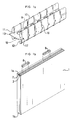
- the device shown in the figures is composed of construction elements whose faces assembly have a longitudinal recess, and assembly parts arranged to be arranged between the assembly faces of two building elements of so as to penetrate into the recesses of the latter.
- the elements of construction 1 represented in FIGS. 1b, 2, 6 and 7 are elements such as tiles, briquettes ... in particular intended for the realization of partitions.
- Each of these building elements has two lateral assembly faces 1a, 1b each having two longitudinal grooves 2, 3 separated by a longitudinal central stud 4 high substantially less than the depth of said grooves.
- This central stud 4 has a section in weakly accented ⁇ shape adapted so that the width of the end of said stud is substantially greater than that of its current portion, so that said end define two longitudinal bands forming spans of contact opposite and parallel to the front faces of building element 1.
- the grooves 2, 3 comprise, as for them, external longitudinal edges presenting transversely a convex shape.
- Each assembly face 1a, 1b forms, in in addition, a longitudinal central bowl 5 in the bottom of which open the grooves 2, 3, said bowl being laterally bordered by two longitudinal flat strips 6, 7 by which the building elements come in support.
- the assembly parts 8 shown in Figures 1a, 3, 4 and 5 and intended to be arranged between the assembly faces 1a, 1b of the construction elements 1 consist of bars whose cross section has the general shape of an H.
- the core 9 of these assembly parts 8 has a thickness suitable for accommodating itself in the interval defined by the bowls 5 on two sides assembly 1a, 1b, opposite. This core 9 is pierced, at regular intervals, circular holes 10 allowing the discharge of the binder during the installation of the parts assembly 8.
- Each branch 11, 12 of this part assembly H-shaped 8 is made up of two wings 11a, 11b, 12a, 12b extending on either side of the soul, and spaced so as to be accommodated each in a groove 2, 3.
- Each of these wings 11a, 11b, 12a, 12b has internal ribs at regular intervals 13, 14 extending orthogonally to the core 9.
- Each of these ribs 13, 14 has a front face flat, and said ribs have a thickness adapted so that the distance between the front faces of two ribs 13, 14 facing each other, ie substantially less than the maximum width of the central stud 4.
- the front faces of the ribs 13, 14 form arranged contact surfaces to cooperate with those of the central stud 4 so as to ensure relative locking without play of the assembly parts 8 and construction elements 1 in one direction orthogonal to the front faces of said elements of construction.
- This arrangement provides a perfect centering between building elements 1 and assembly parts 8 which immediately leads to self-alignment front faces of said elements of construction.
- Each of the wings 11a, 11b, 12a, 12b of the branches 11, 12 of the assembly parts 8 comprises also, in line with each internal rib 13, 14, a external rib 15, 16 giving the connection pieces 8 an overall width adapted to spare a play by relative to the grooves 2, 3 in order to facilitate the implementation places construction elements on these parts assembly 8.
- branches 11, 12, and the internal ribs 13, 14, and external ribs 15, 16 are shaped so that each of said branches and the ribs associated with these have a profile tapered.
- Each branch 11, 12 of the pieces assembly 8 further comprises external bosses 17 bearing on the assembly faces 1a, 1b, capable of ensuring the relative stability and positioning of said parts and assembly faces.
- bosses arranged at the right of each external rib 15, 16, are of a shape adapted to form two support planes parallel to the core 9 extending symmetrically on either side of it, so that give a reversible character to the assembly parts 8.
- these bosses 17 have transversely a general trapezoidal shape centered by relation to the plane of the soul 9.
- the sides of the trapezoid forming the upper and lower faces of these bosses 17 have a concave shape combined with the shape convex of the longitudinal edges of the grooves 2, 3.
- the core 9 is extended at level of one of its ends by a tongue 19 intended to allow the removal of the assembly part 8, if necessary, using a tool inserted between said tongue and the assembly face of the element of construction.
- this core 9 is endowed, at the level from its end opposite to the tongue 19, of a notch 20 of conjugate shape of the section of the studs 4.
- This notch 20 allows, when the height of the last row under the ceiling justifies placing the building elements 1 standing, i.e. with their assembly faces 1a, 1b vertical, to ensure a connection between these building elements and those of the rank inferior.
- this connection is obtained by interposing one of the pieces assembly 8 between the vertical assembly faces 1a, 1b of the building elements of the last row, so that the notch 20 of the latter comes to cap the central stud 4 of one of the construction elements 1 of the penultimate row.
Landscapes
- Engineering & Computer Science (AREA)
- Architecture (AREA)
- Physics & Mathematics (AREA)
- Electromagnetism (AREA)
- Civil Engineering (AREA)
- Structural Engineering (AREA)
- Handcart (AREA)
- Joining Of Building Structures In Genera (AREA)
- Finishing Walls (AREA)
- Connection Of Plates (AREA)
- Forms Removed On Construction Sites Or Auxiliary Members Thereof (AREA)
- Resistance Welding (AREA)
Claims (24)
- Verbindungsstück zum Einsatz bei der Verbindung zweier Bauelemente, insbesondere bei einer Verbindung, die zur Ausbildung von Trennwänden dient, mit einem Mittelbereich (9) und zwei zur beidseits des Mittelbereichs (9) überstehenden Bereichen (11, 12),
dadurch gekennzeichnet,
daß die überstehenden Bereiche (11, 12) so geformt sind, daß sie wenigstens eine Aussparung in bezug auf ihre Randbereiche bilden, die dem Mittelbereich (9) gegenüberliegen, wobei jede der Aussparungen wenigstens zwei Kontaktflächen (13, 14) umfaßt. - Verbindungsstück nach Anspruch 1, dadurch gekennzeichnet, daß es aus einem H-förmigen Profil besteht, dessen Mittelsteg (9) den Mittelbereich bildet und dessen Schenkel (11, 12) die überstehenden Bereiche bilden.
- Verbindungsstück nach Anspruch 2, dadurch gekennzeichnet, daß jeder Schenkel (11, 12) mit inneren Rippen (13, 14) versehen ist, die senkrecht zum Mittelsteg (9) verlaufen und so angeordnet sind, daß sie die Kontaktflächen der Verbindungsstücke bilden.
- Verbindungsstück nach einem der Ansprüche 2 oder 3, dadurch gekennzeichnet, daß jeder Schenkel (11, 12) mit äußeren Rippen (15, 16) ausgestattet ist, die senkrecht zum Mittelsteg (9) verlaufen.
- Verbindungsstück nach den Ansprüchen 2 bis 4 in Kombination, dadurch gekennzeichnet, daß die Schenkel (11, 12) und die inneren Rippen (13, 14) sowie die äußeren Rippen (15, 16) so geformt sind, daß jeder Schenkel (11, 12) und die diesem letzteren zugeordneten Rippen (13, 15) (14, 16) ein sich verjüngendes Profil bilden.
- Verbindungsstück nach einem der Ansprüche 2 bis 5, dadurch gekennzeichnet, daß der Mittelsteg (9) von wenigstens einer Öffnung (10) durchsetzt ist.
- Verbindungsstück nach einem der Ansprüche 2 bis 6, dadurch gekennzeichnet, daß es Stützanschläge umfaßt, die aus Zapfen (17) bestehen, welche relativ zur Außenfläche der Schenkel (11, 12) vorstehen und im wesentlichen in derselben Ebene wie der Mittelsteg (9) verlaufen.
- Verbindungsstück nach Anspruch 7, dadurch gekennzeichnet, daß die Stützzapfen (17) Formen ausbilden, die dazu geeignet sind, zwei parallele Stützebenen festzulegen, die symmetrisch zu beiden Seiten der Ebene des Mittelstegs (9) verlaufen.
- Verbindungsstück nach einem der Ansprüche 2 bis 8, dadurch gekennzeichnet, daß der Mittelsteg (9) auf einem seiner Ränder mit einer Platte (19) verlängert ist.
- Verbindungsstück nach einem der Ansprüche 2 bis 9, dadurch gekennzeichnet, daß der Mittelsteg (9) auf einem seiner Ränder mit einer Platte (19) verlängert ist.
- Bauelement zur Herstellung von Wänden mittels Verbindungsstücken nach einem der Ansprüche 1 bis 10, mit zwei vorderen Flächen, die senkrecht zu zwei seitlichen Verbindungsflächen (1a, 1b) verlaufen, welche wenigstens eine Aussparung aufweisen, die von zwei flachen, in Längsrichtung verlaufenden Bändern (6, 7) begrenzt wird und aus einer ebenfalls in Längsrichtung verlaufenden, zentralen Mulde (5) besteht, in die zwei Längsrillen (2, 3) einmünden, die durch eine zentrale Scheibe (4) oder Rippe in Längsrichtung getrennt sind, die zwei sich gegenüberliegende Kontaktflächen aufweist, welche parallel zu den vorderen Flächen des Bauelementes verlaufen, dadurch gekennzeichnet, daß die zentrale Scheibe (4) ein Endstück mit einer Größe aufweist, die im wesentlichen größer als dessen laufender Teil ist, der die Kontaktflächen der Scheibe festlegt.
- Verbindung, insbesondere zur Herstellung von Zwischenwänden, die zwei Bauelemente (1) nach Anspruch 11, die mit vorderen Flächen und mit Verbindungsflächen (1a, 1b) ausgestattet sind, wobei die Verbindungsflächen (1a, 1b) jeweils mindestens eine Aussparung aufweisen, die von zwei ebenen, in Längsrichtung verlaufenden Bändern (6, 7) begrenzt sind, wobei die Aussparungen der Verbindungsflächen der beiden Bauelemente so angeordnet sind, daß sie sich gegenüberliegen, wenn sie im Hinblick auf die Herstellung einer Zwischenwand angeordnet werden, wobei die beiden Bauelemente (1) über die ebenen, in Längsrichtung verlaufenden Bänder (6, 7) aneinander zur Anlage kommen und ihre vorderen Flächen zueinander ausgerichtet sind, und mindestens ein Verbindungsstück (8) nach einem der Ansprüche 1 bis 10 umfaßt, das in den Aussparungen gegenüber den Bauelementen (1) angeordnet werden kann,
wobeidas Verbindungsstück (8) zwischen den beiden Bauelementen (1) so angeordnet ist, daß sein Mittelsteg (9) in dem Zwischenraum, der durch die zentralen Mulden (5) der beiden Verbindungsflächen (1a, 1b) gegenüber den Bauelementen (1) festgelegt ist, und daß jeder Flügel (11a, 11b; 12a, 12b) der beiden Schenkel (11, 12) in einer Nut (2, 3) der Vertiefungen in den Verbindungsflächen (1a, 1b) angeordnet ist, dadurch gekennzeichnet, daß jeder Flügel (11a, 11b; 12a, 12b) des Verbindungsstücks (8) Kontaktflächen (13, 14) umfaßt derart, daß der diese trennende Abstand kleiner als die maximale Größe einer zentralen Scheibe (4) oder Rippe ist, so daß die Kontaktflächen (13, 14) eine spielfreie, relative Blockierung des Verbindungsstücks (8) und der Bauelemente (1) in wenigstens einer der zu den Verbindungsflächen parallel verlaufenden Richtungen sicherstellen.jede Aussparung der Verbindungsflächen von einer zentralen, in Längsrichtung verlaufenden Mulde (5) gebildet wird, in welche zwei in Längsrichtung verlaufende Nuten (2, 3) einmünden, die über eine zentrale Scheibe (4) oder eine Längsrippe mit zwei sich gegenüberliegenden Kontaktflächen getrennt sind, die parallel zu den vorderen Flächen des Bauelementes (1) verlaufen,jedes Verbindungsstück (8) aus einem Steg mit H-förmigem Querschnitt gebildet ist und einen Mittelsteg (9), der einen zentralen Bereich bildet, sowie zwei Schenkel (11, 12) aufweist, deren jeder von zwei Flügeln (11a, 11b; 12a, 12b) gebildet wird, die zu beiden Seiten des Mittelstegs (9) in einem Abstand zueinander verlaufen derart, daß jeder derselben in einer Nut (2, 3) aufgenommen wird, - Verbindung nach Anspruch 12, dadurch gekennzeichnet, daß die Schenkel (11, 12) jedes Verbindungsstücks (8) eine Form aufweisen, die zum Erzielen eines Spiels zwischen denselben und den äußeren, den Nuten (2, 3) zugewandten Umlaufrändem angepaßt ist.
- Verbindung nach Anspruch 12 oder nach Anspruch 13, dadurch gekennzeichnet, daß jedes Verbindungsstück (8) Anschläge (17) zur Anlage gegen die Verbindungsflächen (1a, 1b) umfaßt, die dazu dienen, die relative Stabilität und Ausrichtung dieser Stücke und der Verbindungsflächen zu gewährleisten.
- Verbindung nach einem der Ansprüche 12 bis 14, dadurch gekennzeichnet, daß die Mittelscheibe (4) jeder Vertiefung ein Endstück mit einer Größe aufweist, die im wesentlichen größer als die seines laufenden Teils ist, und zwei parallele, einander gegenüberliegende Kontaktflächen festlegt.
- Verbindung nach einem der Ansprüche 12 bis 15, dadurch gekennzeichnet, daß jeder Schenkel (11, 12) der Verbindungsstücke (8) mit äußeren Rippen (15, 16) versehen ist, die senkrecht zum Mittelsteg (9) verlaufen und den Verbindungsstücken eine im wesentlichen kleinere Größe als die Gesamtgröße der Nut (2, 3) der Verbindungsflächen (1a, 1b) verleihen.
- Verbindung nach einem der Ansprüche 12 bis 16, dadurch gekennzeichnet, daß jeder Schenkel (11, 12) der Verbindungsstücke (8) mit inneren Rippen (13, 14) ausgestattet ist, die sich senkrecht zum Mittelsteg (9) erstrecken und so angeordnet sind, daß sie die Kontaktflächen der Verbindungsstücke bilden.
- Verbindung nach den Ansprüchen 16 und 17 in Kombination, dadurch gekennzeichnet, daß die Schenkel (11, 12) und die inneren Rippen (13, 14) sowie die äußeren Rippen (15, 16) so geformt sind, daß jeder Schenkel (11, 12) und die diesem letzteren zugeordneten Rippen (13, 15, 14, 16) ein sich verjüngendes Profil bilden.
- Verbindung nach einem der Ansprüche 12 bis 18, dadurch gekennzeichnet, daß der Mittelsteg (9) jedes Verbindungsstücks (8) mit mindestens einer Öffnung (10) durchsetzt ist.
- Verbindung nach einem der Ansprüche 14 bis 19, dadurch gekennzeichnet, daß die Anschläge zum Anliegen gegen die Verbindungsflächen (1a, 1b) aus Anschlagvorsprüngen (17) bestehen, die relativ zur Außenfläche der Schenkel (11, 12) vorstehen und im wesentlichen in derselben Ebene wie der Mittelsteg (9) liegen.
- Verbindung nach Anspruch 20, dadurch gekennzeichnet, daß die Stützvorsprünge (17) Formen aufweisen, die zum Festlegen zweier zum Mittelsteg (9) paralleler Stützebenen dienen, die zu beiden Seiten desselben symmetrisch verlaufen.
- Verbindung nach einem der Ansprüche 20 oder 21, dadurch gekennzeichnet, daß die Nuten (2, 3) in Längsrichtung verlaufende, äußere Ränder umfassen, die in Querrichtung eine konvexe Form aufweisen, wobei die Stützvorsprünge (17) Stützflächen mit einer konjungiert konkaven Form umfassen.
- Verbindung nach einem der Ansprüche 12 bis 22, dadurch gekennzeichnet, daß der Mittelsteg (9) jedes Verbindungsstückes (8) mit einer Zunge (19) auf der Höhe eines seiner Enden verlängert ist.
- Verbindung nach einem der Ansprüche 12 bis 23, dadurch gekennzeichnet, daß der Mittelsteg jedes Verbindungsstückes auf der Höhe eines seiner Enden eine Vertiefung mit einer zur Form des Querschnitts der Mittelscheiben der Verbindungsflächen konjungierten Form aufweist, so daß es möglich ist, bestimmte Bauelemente so anzuordnen, daß ihre Verbindungsflächen senkrecht zu den Verbindungsflächen der Bauelemente der darunter liegenden Reihe verlaufen, und ein Verbindungsstück so anzuordnen, daß seine Aussparung die Mittelscheibe des Bauelementes der darunter liegenden Reihe überdeckt.
Applications Claiming Priority (2)
| Application Number | Priority Date | Filing Date | Title |
|---|---|---|---|
| FR9406494 | 1994-05-24 | ||
| FR9406494A FR2720425B1 (fr) | 1994-05-24 | 1994-05-24 | Dispositif d'assemblage de deux éléments de construction, pièces d'assemblage et éléments de construction conçu pour la réalisation de ce dispositif d'assemblage. |
Publications (2)
| Publication Number | Publication Date |
|---|---|
| EP0684349A1 EP0684349A1 (de) | 1995-11-29 |
| EP0684349B1 true EP0684349B1 (de) | 1999-10-20 |
Family
ID=9463602
Family Applications (1)
| Application Number | Title | Priority Date | Filing Date |
|---|---|---|---|
| EP95201294A Expired - Lifetime EP0684349B1 (de) | 1994-05-24 | 1995-05-18 | Verbindungseinrichtung für zwei Bauelemente, Verbindungsstücke und für diese Einrichtung geeignete Bauelemente |
Country Status (5)
| Country | Link |
|---|---|
| EP (1) | EP0684349B1 (de) |
| AT (1) | ATE185864T1 (de) |
| DE (1) | DE69512828T2 (de) |
| ES (1) | ES2138700T3 (de) |
| FR (1) | FR2720425B1 (de) |
Families Citing this family (3)
| Publication number | Priority date | Publication date | Assignee | Title |
|---|---|---|---|---|
| DE19706897A1 (de) * | 1997-02-21 | 1998-09-03 | Huurne Andre Ter | Mauerwerk aus quaderförmigen Bausteinen |
| NL2018727B1 (en) | 2016-04-18 | 2018-08-14 | B&D Opmeer B V | Method and system for building walls |
| CN111395650A (zh) * | 2020-04-20 | 2020-07-10 | 中建八局第二建设有限公司 | 一种装配式墙体定位机构及定位方法 |
Family Cites Families (7)
| Publication number | Priority date | Publication date | Assignee | Title |
|---|---|---|---|---|
| BE518725A (de) * | ||||
| FR1072942A (fr) * | 1953-03-13 | 1954-09-16 | éléments préfabriqués destinés à la construction de maisons et analogues | |
| FR2307097A1 (fr) * | 1975-04-09 | 1976-11-05 | Messina Fernand | Element creux clavete |
| FR2344690A1 (fr) * | 1976-03-15 | 1977-10-14 | Ind Regionale Batiment | Element de construction |
| AU2841577A (en) * | 1977-08-31 | 1979-03-08 | Montanelli M | Construction of vertical walls of buildings |
| DE8437222U1 (de) * | 1984-12-20 | 1985-04-04 | Lüdenscheider Betonstein- und Mischwerke GmbH & Co KG, 5880 Lüdenscheid | Formstein |
| US4986048A (en) * | 1990-01-11 | 1991-01-22 | Pittsburgh Corning Corporation | Method and apparatus for erecting a glass block wall |
-
1994
- 1994-05-24 FR FR9406494A patent/FR2720425B1/fr not_active Expired - Lifetime
-
1995
- 1995-05-18 AT AT95201294T patent/ATE185864T1/de not_active IP Right Cessation
- 1995-05-18 ES ES95201294T patent/ES2138700T3/es not_active Expired - Lifetime
- 1995-05-18 EP EP95201294A patent/EP0684349B1/de not_active Expired - Lifetime
- 1995-05-18 DE DE69512828T patent/DE69512828T2/de not_active Expired - Fee Related
Also Published As
| Publication number | Publication date |
|---|---|
| ATE185864T1 (de) | 1999-11-15 |
| EP0684349A1 (de) | 1995-11-29 |
| DE69512828T2 (de) | 2000-06-15 |
| FR2720425A1 (fr) | 1995-12-01 |
| FR2720425B1 (fr) | 1996-08-02 |
| DE69512828D1 (de) | 1999-11-25 |
| ES2138700T3 (es) | 2000-01-16 |
Similar Documents
| Publication | Publication Date | Title |
|---|---|---|
| EP0241344B1 (de) | Verbindungsvorrichtung für ein Rahmengerüst von Ständen für vorübergehende Ausstellungen | |
| EP0694105B1 (de) | Doppelboden mit modulbodenplatten | |
| EP0122210B1 (de) | Glaselement, insbesondere Ziegel- oder Pflasterstein | |
| EP0098784B1 (de) | Elastisches Montageverfahren von zwei Teilen | |
| EP0684349B1 (de) | Verbindungseinrichtung für zwei Bauelemente, Verbindungsstücke und für diese Einrichtung geeignete Bauelemente | |
| EP4060143B1 (de) | Bauelement | |
| FR2831339A1 (fr) | Support de barres collectrices | |
| EP0975843B1 (de) | Wandaufbau mit vorrichtung zum verbinden der holzbretter des wandaufbaus | |
| FR2674581A1 (fr) | Dispositif d'assemblage pour profiles creux. | |
| EP2753760A1 (de) | Metallträger zur herstellung eines bestandteils des pfeilers einer brücke | |
| FR2754285A1 (fr) | Element de coffrage isolant pour mur en beton | |
| EP0994994B1 (de) | Paneele für eine schwimmbadwand | |
| EP2065529A1 (de) | Verbundständer für die Erstellung einer Trennwand und einen solchen Ständer umfassende Trennwand | |
| FR2588903A1 (fr) | Escalier en carreaux de ceramique poses sur du beton | |
| WO2017137629A1 (fr) | Dispositif modulaire pour revetement de sol et structure modulaire de revetement de sol associee | |
| EP1371785B1 (de) | Vorgefertigtes Element für ein Mannloch und Mannloch | |
| FR2809143A1 (fr) | Dispositif d'assemblage de panneaux de bois | |
| BE1006113A3 (fr) | Mur assemble. | |
| EP3070223B1 (de) | Geradlinige einfassung eines bauelements, und mit einer solchen einfassung versehenes bauelement | |
| FR2586732A1 (fr) | Ensemble de construction pour la realisation de cloisons ou de parois modulaires | |
| EP1838931B1 (de) | Bauelemente und eine mauerwerksbefestigungswand aus diesen elementen | |
| FR2550811A1 (fr) | Jeu d'elements de construction pour mur de soutenement | |
| BE429696A (de) | ||
| FR2996866A1 (fr) | Entrevous | |
| FR2567939A1 (fr) | Blocs prefabriques pour l'edification de murs, possedant des moyens de positionnement relatif ameliores |
Legal Events
| Date | Code | Title | Description |
|---|---|---|---|
| PUAI | Public reference made under article 153(3) epc to a published international application that has entered the european phase |
Free format text: ORIGINAL CODE: 0009012 |
|
| AK | Designated contracting states |
Kind code of ref document: A1 Designated state(s): AT BE DE ES FR GB IT LU NL PT |
|
| 17P | Request for examination filed |
Effective date: 19960129 |
|
| 17Q | First examination report despatched |
Effective date: 19971020 |
|
| GRAG | Despatch of communication of intention to grant |
Free format text: ORIGINAL CODE: EPIDOS AGRA |
|
| GRAG | Despatch of communication of intention to grant |
Free format text: ORIGINAL CODE: EPIDOS AGRA |
|
| GRAG | Despatch of communication of intention to grant |
Free format text: ORIGINAL CODE: EPIDOS AGRA |
|
| GRAH | Despatch of communication of intention to grant a patent |
Free format text: ORIGINAL CODE: EPIDOS IGRA |
|
| GRAH | Despatch of communication of intention to grant a patent |
Free format text: ORIGINAL CODE: EPIDOS IGRA |
|
| GRAA | (expected) grant |
Free format text: ORIGINAL CODE: 0009210 |
|
| AK | Designated contracting states |
Kind code of ref document: B1 Designated state(s): AT BE DE ES FR GB IT LU NL PT |
|
| PG25 | Lapsed in a contracting state [announced via postgrant information from national office to epo] |
Ref country code: NL Free format text: LAPSE BECAUSE OF FAILURE TO SUBMIT A TRANSLATION OF THE DESCRIPTION OR TO PAY THE FEE WITHIN THE PRESCRIBED TIME-LIMIT Effective date: 19991020 Ref country code: IT Free format text: LAPSE BECAUSE OF FAILURE TO SUBMIT A TRANSLATION OF THE DESCRIPTION OR TO PAY THE FEE WITHIN THE PRESCRIBED TIME-LIMIT;WARNING: LAPSES OF ITALIAN PATENTS WITH EFFECTIVE DATE BEFORE 2007 MAY HAVE OCCURRED AT ANY TIME BEFORE 2007. THE CORRECT EFFECTIVE DATE MAY BE DIFFERENT FROM THE ONE RECORDED. Effective date: 19991020 Ref country code: GB Free format text: LAPSE BECAUSE OF FAILURE TO SUBMIT A TRANSLATION OF THE DESCRIPTION OR TO PAY THE FEE WITHIN THE PRESCRIBED TIME-LIMIT Effective date: 19991020 |
|
| REF | Corresponds to: |
Ref document number: 185864 Country of ref document: AT Date of ref document: 19991115 Kind code of ref document: T |
|
| RIN1 | Information on inventor provided before grant (corrected) |
Inventor name: WENDLING, LUC, FREDERIC |
|
| REF | Corresponds to: |
Ref document number: 69512828 Country of ref document: DE Date of ref document: 19991125 |
|
| REG | Reference to a national code |
Ref country code: ES Ref legal event code: FG2A Ref document number: 2138700 Country of ref document: ES Kind code of ref document: T3 |
|
| PG25 | Lapsed in a contracting state [announced via postgrant information from national office to epo] |
Ref country code: PT Free format text: LAPSE BECAUSE OF FAILURE TO SUBMIT A TRANSLATION OF THE DESCRIPTION OR TO PAY THE FEE WITHIN THE PRESCRIBED TIME-LIMIT Effective date: 20000120 |
|
| NLV1 | Nl: lapsed or annulled due to failure to fulfill the requirements of art. 29p and 29m of the patents act | ||
| GBV | Gb: ep patent (uk) treated as always having been void in accordance with gb section 77(7)/1977 [no translation filed] |
Effective date: 19991020 |
|
| PLBE | No opposition filed within time limit |
Free format text: ORIGINAL CODE: 0009261 |
|
| STAA | Information on the status of an ep patent application or granted ep patent |
Free format text: STATUS: NO OPPOSITION FILED WITHIN TIME LIMIT |
|
| 26N | No opposition filed | ||
| PGFP | Annual fee paid to national office [announced via postgrant information from national office to epo] |
Ref country code: LU Payment date: 20040604 Year of fee payment: 10 |
|
| PG25 | Lapsed in a contracting state [announced via postgrant information from national office to epo] |
Ref country code: LU Free format text: LAPSE BECAUSE OF NON-PAYMENT OF DUE FEES Effective date: 20050518 |
|
| PGFP | Annual fee paid to national office [announced via postgrant information from national office to epo] |
Ref country code: ES Payment date: 20080429 Year of fee payment: 14 Ref country code: DE Payment date: 20080523 Year of fee payment: 14 |
|
| PGFP | Annual fee paid to national office [announced via postgrant information from national office to epo] |
Ref country code: AT Payment date: 20080429 Year of fee payment: 14 |
|
| PGFP | Annual fee paid to national office [announced via postgrant information from national office to epo] |
Ref country code: BE Payment date: 20080513 Year of fee payment: 14 |
|
| BERE | Be: lapsed |
Owner name: S.A. TUILERIES BRIQUETERIES DU LAURAGAIS *GUIRAUD Effective date: 20090531 |
|
| PG25 | Lapsed in a contracting state [announced via postgrant information from national office to epo] |
Ref country code: AT Free format text: LAPSE BECAUSE OF NON-PAYMENT OF DUE FEES Effective date: 20090518 |
|
| PG25 | Lapsed in a contracting state [announced via postgrant information from national office to epo] |
Ref country code: DE Free format text: LAPSE BECAUSE OF NON-PAYMENT OF DUE FEES Effective date: 20091201 Ref country code: BE Free format text: LAPSE BECAUSE OF NON-PAYMENT OF DUE FEES Effective date: 20090531 |
|
| REG | Reference to a national code |
Ref country code: ES Ref legal event code: FD2A Effective date: 20090519 |
|
| PG25 | Lapsed in a contracting state [announced via postgrant information from national office to epo] |
Ref country code: ES Free format text: LAPSE BECAUSE OF NON-PAYMENT OF DUE FEES Effective date: 20090519 |
|
| PGFP | Annual fee paid to national office [announced via postgrant information from national office to epo] |
Ref country code: FR Payment date: 20120601 Year of fee payment: 18 |
|
| REG | Reference to a national code |
Ref country code: FR Ref legal event code: ST Effective date: 20140131 |
|
| PG25 | Lapsed in a contracting state [announced via postgrant information from national office to epo] |
Ref country code: FR Free format text: LAPSE BECAUSE OF NON-PAYMENT OF DUE FEES Effective date: 20130531 |