EP0683073A1 - A partitioning device for protecting the compartment behind the front or rear seat of a motor vehicle - Google Patents
A partitioning device for protecting the compartment behind the front or rear seat of a motor vehicle Download PDFInfo
- Publication number
- EP0683073A1 EP0683073A1 EP95106624A EP95106624A EP0683073A1 EP 0683073 A1 EP0683073 A1 EP 0683073A1 EP 95106624 A EP95106624 A EP 95106624A EP 95106624 A EP95106624 A EP 95106624A EP 0683073 A1 EP0683073 A1 EP 0683073A1
- Authority
- EP
- European Patent Office
- Prior art keywords
- frame section
- backrest
- section
- upper frame
- sections
- Prior art date
- Legal status (The legal status is an assumption and is not a legal conclusion. Google has not performed a legal analysis and makes no representation as to the accuracy of the status listed.)
- Granted
Links
Images


Classifications
-
- B—PERFORMING OPERATIONS; TRANSPORTING
- B60—VEHICLES IN GENERAL
- B60R—VEHICLES, VEHICLE FITTINGS, OR VEHICLE PARTS, NOT OTHERWISE PROVIDED FOR
- B60R21/00—Arrangements or fittings on vehicles for protecting or preventing injuries to occupants or pedestrians in case of accidents or other traffic risks
- B60R21/02—Occupant safety arrangements or fittings, e.g. crash pads
- B60R21/026—Rigid partitions inside vehicles, e.g. between passengers and load compartments
Definitions
- the invention relates to a device for the protective separation of the space behind the front or rear seat of a passenger car according to the preamble of claim 1.
- the invention has for its object to provide a device for the protective separation of the space behind the front or rear seats of a passenger car, which can be permanently installed and still be put into and out of operation. Furthermore, it should be usable with the backrest of the rear seats raised as well as with the backrest folded forward.
- the device according to the invention provides a protective frame made of rigid material, preferably hollow rod material is made.
- a lower frame section can be suitably releasably attached to the back of the back of the rear seat. It remains in the fixed position when the backrest is folded up.
- the upper frame section can, however, between a lower position in which it is largely covered by the backrest and an upper position in which the upper frame section abuts the ceiling of the body or ends at a short distance from it.
- the upper frame section is fastened in a suitable manner to the ceiling and / or to the pillar of the body, for example by means of a screw or snap fastening.
- the upper frame section is guided telescopically on the lower one, whereby tubular hollow profiles expediently cooperate in order to be able to carry out the adjustment in a simple manner.
- tubular hollow profiles expediently cooperate in order to be able to carry out the adjustment in a simple manner.
- the back of the rear seats is often divided.
- an embodiment of the invention provides that a separate protective frame is assigned to each backrest section.
- the upper frame section can be connected to the roof or laterally to the pillar of the body by means of screws or a snap connection.
- a strut to the upper frame section, which strut is then attached to a column or another part of the body and extending rearwards. Since the wheel arches narrow the interior and the protective device should largely cover the width of the interior, an embodiment of the invention provides that the upper frame section has an ear-shaped projection at the upper end on the side facing the body.
- the backrest usually has a backward slope. If the upper frame section had the same inclination, this would result in a reduction in the loading space. Therefore, an embodiment of the invention provides that the lower facing ends of the telescopically cooperating profile sections are designed so that the upper frame section with the lower an obtuse angle forms and the upper frame section is arranged vertically in the upper position.
- the mutually facing ends of the hollow profiles can be connected according to a further embodiment of the invention by a screw connection, which can be made relatively stable.
- the protective frame can act as a roll bar.
- an embodiment of the invention provides that the lower frame section in a second position on the back of the folded backrest can be detachably attached to it. With the backrest folded forward, the frame section therefore stands up at the free end of the backrest, approximately at an angle of 90 °.
- the upper frame section which now has a further forward position (behind the front seats), is also to be connected at this point in a suitable manner to the body, for example to the ceiling or the pillars of the body using a suitable snap or screw connection or the like.
- the underside of the lower frame section is also to be attached to the backrest in a suitable manner in this position.
- one embodiment of the invention provides that a guide is attached in the backrest, on which a guide section of the lower frame section is slidably adjustable between a stop in the lower region and a stop in the upper area of the backrest. If the backrest is folded forward, the entire frame of the guide can slide along and be fixed in the new position, as described above. In principle, it is sufficient if the lower frame section lies against a stop of the guide. However, it can also be expedient to provide suitable snap connection means between the frame section and the guide in order to hold the lower frame section in the assumed position.
- an embodiment of the invention proposes that a connecting strut is provided between the protective frame sections. This can be sent to the End have lateral lugs that fit into the hollow profile of the upper frame sections.
- the connecting strut can also serve to support a roll having a net. The network can then be pulled down in the manner of a roller blind to the bottom of the motor vehicle and fastened to it in a suitable manner. This also creates a protective partition between the two rear seats.
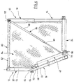
- FIG. 1 to 4 show two protective frames 10, 12 which consist of a lower frame section 14 and 16 and an upper frame section 18 and 20, respectively.
- the lower frame section 14 or 16 is provided with two parallel struts 22, 24 which are connected to cross struts 26, 28.
- the struts 22 to 28 consist of hollow profile material, for example a box profile.
- Fastening struts 30, 32 are also connected to the cross struts 26, 28 and run parallel and at a distance from the struts 22, 24. They are used to attach to a backrest of a passenger car, only shown schematically, for example of the caravan type. The attachment can be carried out, for example, by means of a snap connection 36, as is shown separately in FIG.
- the attachment of the lower frame part 16 to the separate rear seat 42 is analogous to that of the lower frame section 14, with guide rails 44, 46 also being embedded in the rear seat 42.
- the snap connection 36 is provided in the same way.
- the lower frame section 14, 16 can be lined up to the level of the upper edge of the seats 34, 42, for example in order to hide the guide rails.
- the struts 22, 24 have a free extension 50, 52 which engage in corresponding struts 54, 56 of the upper frame section 18 telescopically.
- the upper frame section 18 and 20 is shown completely pulled out. However, it can be lowered, the upper cross strut 58 or 60 being approximately at the top of the backrest 34, 42.
- section 50 is chamfered, as can be seen in dashed lines at 62.
- the upper frame section 20 can be pivoted vertically, while the lower frame section 16 is arranged in accordance with the inclination of the backrest 42.
- a stable screw 64 can be provided in the connection area in order to firmly connect the lower and upper frame sections 16, 20 to one another, both in the position according to FIG. 1 and also according to FIG. 2 (see also FIG. 4). For this, however, it is necessary to provide two different through holes in the section 50, 52.
- the cross struts 58, 60 can, as indicated by dash-dotted lines at 66, be screwed to the ceiling of the body or connected via a snap connection. Additionally or alternatively, it is possible to releasably connect the upper frame sections 18, 20 laterally to a pillar of the body by means of side attachments 68, 70 by means of a screw or snap connection. Finally, with the extension 68, 70, a telescopic rod 72 can be connected in an articulated manner, as indicated at 74, the telescopic rod 72 then being able to be connected horizontally in the vehicle to a rear pillar or another attachment option. For this, however, it is necessary that the length of the telescopic connection 72 can be set as desired.
- the protective frames 10, 12 are located on the back of the backrests of the rear seats with the frame sections 14, 16 bearing against the back of the backrest. 2, the backrests 34, 42 are folded towards the front seats.
- the frames 18, 20 are pushed forward with the help of the guide shoes, not shown, along the guide rails 38, 40 or 44, 46 against a stop (not shown), as a result of which the frames 18, 20 are located behind the front seats in the free edge area of the front folded backrest. In this position, they are also attached to the ceiling or to a pillar via the side extensions 68, 70.
- a releasable fixation of the lower frame section 14, 16 can be provided in order to prevent subsequent movement.
- This position of the protective frame is shown in Fig. 2.
- a third is shown in Figures 3 and 4.
- the frame 12 has the same position as in the position according to FIG. 1, ie behind the folded backrest of the one rear seat.
- the second frame 10 has a position as can be seen in FIG. 2, that is to say pushed forward behind the front seats (as can be seen, the front seats and also the position of the rear seats of the body as well the body parts not shown).
- a distance is thus created between the frames 10, 12, as can be seen in FIG. 4. This creates a gap through which objects can pass from the loading space to the seating area of the cabin.
- a connecting strut 80 is proposed (FIG.
- the connecting strut 80 supports the frames 10, 12 against each other.
- a roller is mounted, as indicated by dashed lines at 82.
- a net 84 for example made of carbon fibers, is rolled up on this. The net can be pulled off the roller 82 in the manner of a roller blind and fastened in a suitable manner to the floor of the vehicle (fastening not shown).
- a telescopic rod 86 which consists of a tube 88 and a rod 90 slidably received therein, is articulated at 92 on the connecting strut 80 at the upper end.
- the lower end of the rod 90 has an eyelet (shown in broken lines), which is designated by 94 and can be pushed onto a hook 96 on the floor of the vehicle.
- the telescopic rod is also an obstacle to the passage through the space between frames 10, 12.
- screws 96 are indicated with knurled head. As indicated in the embodiment according to FIG. 5, they can be taken up by the attachment 68, 70, as shown at 98. In this way, the attachment of the upper frame section 14, 16 to a pillar of the body can be accomplished particularly easily.
- FIG. 6 the connecting strut 80 with articulated telescopic strut 86 is shown separately.
- FIG. 7 shows a wrinkle of the connecting strut 80 constantly via a ring 100 on a round rod 102 which carries insert pieces 104, 106 at the ends.
- the telescopic tube 86 is also articulated via a ring 108.
- FIG. 7 shows the arrangement for the position according to FIG. 2, in which both frame parts 10, 20 are arranged behind the front sides.
- the right piece 106 is completely inserted into the hollow profile 60 and the left one releases the profile 58.
- a leaf spring 110 is attached above both with a centrally welded pin which engages in a slot (not shown) of the profile 60 and can be locked therein by suitable measures.
- a block 112 is mounted so as to be pivotable about the axis of the strut 80 in order to be optionally inserted into the associated lower hollow profile.
- the frame parts can be suitably filled, e.g. with a grid, a mesh of wire or textile fibers or the like to develop the protective effect on smaller objects.
Abstract
Description
Die Erfindung bezieht sich auf eine Vorrichtung zur schutzweisen Abtrennung des Raumes hinter dem Vorder- oder Hintersitz eines Personenkraftwagens nach dem Oberbegriff des Patentanspruchs 1.The invention relates to a device for the protective separation of the space behind the front or rear seat of a passenger car according to the preamble of claim 1.
Es ist für als Caravans bezeichnete Peronenkraftwagen bekannt, den nach oben und vorn offenen Laderaum gegenüber dem eigentlichen Sitzraum durch geeignete Trennmittel abzutrennen, welche verhindern, daß bei Bremsmanövern oder dergleichen Gegenstände aus dem Laderaum in die Kabine gelangen und Personen gefährden. Es ist zum Beispiel bekannt, einen Rahmen aus Rohrmaterial hinter den Rücksitz zu montieren, wobei im Rahmen ein Netz oder dergleichen aufgespannt ist. Eine derartige Schutzvorrichtung nimmt nur eine feste Position ein. Ein wahlweiser Zugang zum Laderaum vom Wageninneren ist nicht möglich. Falls es erwünscht ist, muß die Schutzvorrichtung komplett entfernt werden. Bei vielen Personenkraftwagen kann die Ladefläche durch ein Nachvornklappen der Rückenlehne der Hintersitze vergrößert werden. Für einen solchen Fall ist die bekannte Schutzvorrichtung nicht geeignet.It is known for personal vehicles known as caravans to separate the cargo space, which is open upwards and to the front, from the actual seating space by means of suitable separating means, which prevent objects from getting into the cabin from the cargo space during braking maneuvers or the like and endanger people. For example, it is known to mount a frame made of tubular material behind the rear seat, a net or the like being stretched in the frame. Such a protective device only occupies a fixed position. An optional access to the cargo area from the inside of the car is not possible. If desired, the protective device must be removed completely. In many passenger cars, the loading area can be enlarged by folding forward the backrest of the rear seats. The known protective device is not suitable for such a case.
Der Erfindung liegt die Aufgabe zugrunde, eine Vorrichtung zur schutzweisen Abtrennung des Raums hinter den Vorder- oder Hintersitzen eines Personenkraftfahrzeugs zu schaffen, die dauerhaft installiert und gleichwohl wahlweise in und außer Betrieb genommen werden kann. Ferner soll sie sowohl bei hochgestellter als auch bei nach vorn geklappter Rückenlehne der Hintersitze verwendbar sein.The invention has for its object to provide a device for the protective separation of the space behind the front or rear seats of a passenger car, which can be permanently installed and still be put into and out of operation. Furthermore, it should be usable with the backrest of the rear seats raised as well as with the backrest folded forward.
Diese Aufgabe wird durch die Merkmale des Patentanspruchs 1 gelöst.This object is achieved by the features of patent claim 1.
Die erfindungsgemäße Vorrichtung sieht einen Schutzrahmen vor, der aus steifem Material, vorzugsweise hohlem Stangenmaterial hergestellt ist. Ein unterer Rahmenabschnitt kann in geeigneter Weise an der Rückseite der Rücklehne des hinteren Sitzes lösbar angebracht werden. Er bleibt in der hochgeklappten Stellung der Rückenlehne in fester Position. Demgegenüber kann indessen der obere Rahmenabschnitt zwischen einer unteren Position, in der er weitgehend durch die Rückenlehne verdeckt ist und einer oberen Position, in der der obere Rahmenabschnitt an die Decke der Karosserie anstößt oder in geringem Abstand zu dieser endet. Der obere Rahmenabschnitt wird dabei in geeigneter Weise an der Decke und/oder an der Säule der Karosserie befestigt, beispielsweise durch eine Schraub- oder Schnappbefestigung.The device according to the invention provides a protective frame made of rigid material, preferably hollow rod material is made. A lower frame section can be suitably releasably attached to the back of the back of the rear seat. It remains in the fixed position when the backrest is folded up. In contrast, the upper frame section can, however, between a lower position in which it is largely covered by the backrest and an upper position in which the upper frame section abuts the ceiling of the body or ends at a short distance from it. The upper frame section is fastened in a suitable manner to the ceiling and / or to the pillar of the body, for example by means of a screw or snap fastening.
Der obere Rahmenabschnitt ist teleskopisch am unteren geführt, wobei zweckmäßigerweise rohrartige Hohlprofile zusammenwirken, um die Verstellung auf einfache Weise bewerkstelligen zu können. In der oberen Position des oberen Rahmenabschnitts ist mithin eine ausreichende Abtrennung zwischen dem Laderaum und dem Sitzraum des Fahrzeugs gewährleistet. In der abgesenkten Stellung des oberen Rahmenabschnitts ist der Laderaum vom Inneren der Kabine frei zugänglich.The upper frame section is guided telescopically on the lower one, whereby tubular hollow profiles expediently cooperate in order to be able to carry out the adjustment in a simple manner. In the upper position of the upper frame section, an adequate separation between the cargo space and the seat space of the vehicle is thus ensured. In the lowered position of the upper frame section, the cargo space is freely accessible from inside the cabin.
Häufig ist die Rückenlehne der hinteren Sitze geteilt.The back of the rear seats is often divided.
Daher sieht eine Ausgestaltung der Erfindung vor, daß jedem Rückenlehnenabschnitt ein getrennter Schutzrahmen zugeordnet ist.Therefore, an embodiment of the invention provides that a separate protective frame is assigned to each backrest section.
Wie erwähnt, kann der obere Rahmenabschnitt mit Hilfe von Schrauben oder einer Schnappverbindung mit dem Dach oder seitlich mit der Säule der Karosserie verbunden werden. Alternativ besteht auch die Möglichkeit, mit dem oberen Rahmenabschnitt eine Strebe seitlich zu verbinden, die dann sich nach hinten erstreckend an einer Säule oder einem anderen Teil der Karosserie befestigt wird. Da die Radkästen den Innenraum verschmälern und die Schutzvorrichtung die Breite des Innenraume weitgehend abdecken soll, sieht eine Ausgestaltung der Erfindung vor, daß der obere Rahmenabschnitt am oberen Ende an der der Karosserie zugewandten Seite einen ohrförmigen Ansatz aufweist.As mentioned, the upper frame section can be connected to the roof or laterally to the pillar of the body by means of screws or a snap connection. As an alternative, there is also the possibility of laterally connecting a strut to the upper frame section, which strut is then attached to a column or another part of the body and extending rearwards. Since the wheel arches narrow the interior and the protective device should largely cover the width of the interior, an embodiment of the invention provides that the upper frame section has an ear-shaped projection at the upper end on the side facing the body.
Die Rückenlehne hat in aller Regel eine Neigung nach hinten. Hätte der obere Rahmenabschnitt die gleiche Neigung, würde dadurch eine Verkleinerung des Laderaums stattfinden. Daher sieht eine Ausgestaltung der Erfindung vor, daß die unteren zugekehrten Enden der teleskopisch zusammenwirkenden Profilabschnitte so ausgebildet sind, daß der obere Rahmenabschnitt mit dem unteren einen stumpfen Winkel bildet und der obere Rahmenabschnitt in der oberen Stellung vertikal angeordnet ist. Die einander zugekehrten Enden der Hohlprofile können nach einer weiteren Ausgestaltung der Erfindung durch eine Schraubverbindung verbunden sein, die relativ stabil ausgeführt werden kann. In diesem Fall kann der Schutzrahmen die Funktion eines Überrollbügels übernehmen.The backrest usually has a backward slope. If the upper frame section had the same inclination, this would result in a reduction in the loading space. Therefore, an embodiment of the invention provides that the lower facing ends of the telescopically cooperating profile sections are designed so that the upper frame section with the lower an obtuse angle forms and the upper frame section is arranged vertically in the upper position. The mutually facing ends of the hollow profiles can be connected according to a further embodiment of the invention by a screw connection, which can be made relatively stable. In this case, the protective frame can act as a roll bar.
In zahlreichen Personenkraftwagen des Caravantyps können die Rückenlehnen der Hintersitze nach vorn geklappt werden, um den Laderaum zu vergrößern. Daher sieht eine Ausgestaltung der Erfindung vor, daß der untere Rahmenabschnitt in einer zweiten Stellung auf der Rückseite der nach vorn geklappten Rückenlehne aufstehend an dieser lösbar anbringbar ist. Bei nach vorn geklappter Rückenlehne steht mithin der Rahmenabschnitt an dem freien Ende der Rückenlehne auf, etwa im Winkel von 90°. Der obere Rahmenabschnitt, der nunmehr eine weiter vorn liegende Position hat (hinter den Vordersitzen), ist an dieser Stelle ebenfalls in geeigneter Weise mit der Karosserie zu verbinden, beispielsweise mit der Decke oder den Säulen der Karosserie mit Hilfe einer geeigneten Schnapp- oder Schraubverbindung oder dergleichen. Die Unterseite des unteren Rahmenabschnitts ist in dieser Position ebenfalls in geeigneter Weise an der Rückenlehne anzubringen.In numerous caravan-type passenger cars, the backrests of the rear seats can be folded forward to increase the loading space. Therefore, an embodiment of the invention provides that the lower frame section in a second position on the back of the folded backrest can be detachably attached to it. With the backrest folded forward, the frame section therefore stands up at the free end of the backrest, approximately at an angle of 90 °. The upper frame section, which now has a further forward position (behind the front seats), is also to be connected at this point in a suitable manner to the body, for example to the ceiling or the pillars of the body using a suitable snap or screw connection or the like. The underside of the lower frame section is also to be attached to the backrest in a suitable manner in this position.
Um eine Lagerveränderung der erfindungsgemäßen Schutzvorrichtung in der beschriebenen Art und Weise leicht vorzunehmen, sieht eine Ausgestaltung der Erfindung vor, daß in der Rückenlehne eine Führung angebracht ist, an der ein Führungsabschnitt des unteren Rahmenabschnitts gleitend verstellbar ist zwischen einem Anschlag im unteren Bereich und einem Anschlag im oberen Bereich der Rückenlehne. Wird die Rückenlehne nach vorn geklappt, kann der komplette Rahmen der Führung entlanggleiten und in der neuen Stellung fixiert werden, wie oben beschrieben. Im Prinzip reicht aus, wenn der untere Rahmenabschnitt an einem Anschlag der Führung anliegt. Es kann jedoch auch zweckmäßig sein, zwischen Rahmenabschnitt und Führung geeignete Schnappverbindungsmittel vorzusehen, um den unteren Rahmenabschnitt in der eingenommenen Stellung zu halten.In order to make a change in the bearing of the protective device according to the invention in the manner described, one embodiment of the invention provides that a guide is attached in the backrest, on which a guide section of the lower frame section is slidably adjustable between a stop in the lower region and a stop in the upper area of the backrest. If the backrest is folded forward, the entire frame of the guide can slide along and be fixed in the new position, as described above. In principle, it is sufficient if the lower frame section lies against a stop of the guide. However, it can also be expedient to provide suitable snap connection means between the frame section and the guide in order to hold the lower frame section in the assumed position.
Wie erwähnt, kann bei einer geteilten Ausführung der Rückenlehne nur ein Rückenlehnenabschnitt nach vorn geklappt sein, während der andere seine hochgeklappte Stellung behält. Auch in diesem Fall ist die erfindungsgemäße Schutzvorrichtung wirksam einzusetzen. Um eine Stabilisierung zwischen den beiden Schutzrahmen für die Rückenlehnenabschnitte vorzusehen, schlägt eine Ausgestaltung der Erfindung vor, daß eine Verbindungsstrebe zwischen den Schutzrahmenabschnitten vorgesehen ist. Diese kann an den Enden seitliche Ansätze aufweisen, die passend in das Hohlprofil der oberen Rahmenabschnitte eingreifen. Die Verbindungsstrebe kann auch dazu dienen, eine ein Netz aufweisende Rolle zu lagern. Das Netz kann dann nach Art eines Rollos heruntergezogen werden bis zum Boden des Kraftfahrzeugs und an diesem in geeigneter Weise befestigt werden. Dadurch ist auch eine schützende Abtrennung zwischen den beiden Rücksitzen geschaffen.As mentioned, in a split version of the backrest, only one backrest section can be folded forward, while the other remains in its folded-up position. In this case too, the protective device according to the invention can be used effectively. In order to provide stabilization between the two protective frames for the backrest sections, an embodiment of the invention proposes that a connecting strut is provided between the protective frame sections. This can be sent to the End have lateral lugs that fit into the hollow profile of the upper frame sections. The connecting strut can also serve to support a roll having a net. The network can then be pulled down in the manner of a roller blind to the bottom of the motor vehicle and fastened to it in a suitable manner. This also creates a protective partition between the two rear seats.
Ausführungsführungsbeispiele der Erfindung werden nachfolgend anhand von Zeichnungen näher erläutert.
- Fig. 1
- zeigt eine Rückansicht eines Ausführungsbeispiels der erfindungsgemäßen Schutzvorrichtung in der hinteren Position.
- Fig. 2
- zeigt die Rückansicht der Schutzvorrichtung nach Fig. 1 in der vorderen Position.
- Fig. 3
- zeigt die Rückansicht der Vorrichtung nach Fig. 1 mit dem linken Abschnitt in der hinteren und dem rechten Abschnitt in der vorderen Position.
- Fig. 4
- zeigt eine Seitenansicht der Darstellung nach Fig. 3 in Richtung Pfeil 4.
- Fig. 5
- zeigt eine Einzelheit der Schutzvorrichtung nach den Figuren 1 bis 4.
- Fig. 6
- zeigt eine weitere Einzelheit der Schutzvorrichtung nach den Figuren 1 bis 4.
- Fig. 7
- zeigt eine Einzelheit zur Anbringung von Streben.
- Fig. 1
- shows a rear view of an embodiment of the protective device according to the invention in the rear position.
- Fig. 2
- shows the rear view of the protective device of FIG. 1 in the front position.
- Fig. 3
- shows the rear view of the device of FIG. 1 with the left portion in the rear and the right portion in the front position.
- Fig. 4
- 3 shows a side view of the illustration according to FIG. 3 in the direction of
arrow 4. - Fig. 5
- shows a detail of the protective device according to Figures 1 to 4.
- Fig. 6
- shows a further detail of the protective device according to Figures 1 to 4.
- Fig. 7
- shows a detail for attaching struts.
In den Figuren 1 bis 4 sind zwei Schutzrahmen 10, 12 dargestellt, die aus einem unteren Rahmenabschnitt 14 bzw. 16 und einem oberen Rahmenabschnitt 18 bzw. 20 bestehen. Der untere Rahmenabschnitt 14 bzw. 16 ist mit zwei parallelen Streben 22, 24 versehen, die mit Querstreben 26, 28 verbunden sind. Die Streben 22 bis 28 bestehen aus Hohlprofilmaterial, beispielsweise einem Kastenprofil. Mit den Querstreben 26, 28 sind ferner Befestigungsstreben 30, 32 verbunden, die parallel und im Abstand zu den Streben 22, 24 verlaufen. Sie dienen zur Befestigung an einer nur schematisch dargestellten Rückenlehne der Rücksitze eines PKW, zum Beispiel des Caravantyps. Die Befestigung kann zum Beispiel mittels einer Schnappverbindung 36 erfolgen, wie sie in Fig. 1 getrennt herausgestellt ist mit einem Dorn 38, der in eine federnde Ausnehmung 40 mit Hinterschnitt einrastet. Mit der Querstrebe 28 sind Gleitschuhe verbunden (nicht zu sehen), die in kanalartigen Führungen 38, 40 gleiten. In der in Fig. 1 dargestellten Position liegen die Schuhe gegen einen Anschlag in der Führung 38, 40 und stützen daher den Rahmen 10 nach unten ab. Die Schnappverbindungen 36 halten den unteren Rahmenabschnitt 14 gegen die entsprechend ausgebildete Rückseite der Rückenlehne 34. Die Führungsschienen 38, 40 sind vorzugsweise in die Rückenlehne 34 eingelassen.1 to 4 show two
Die Anbringung des unteren Rahmenteils 16 am getrennten Rücksitz 42 ist analog wie die des unteren Rahmenabschnitts 14, wobei am Rücksitz 42 ebenfalls Führungsschienen 44, 46 eingelassen sind. Die Schnappverbindung 36 ist in gleicher Weise vorgesehen. Bis in Höhe der Oberkante der Sitze 34, 42 kann der untere Rahmenabschnitt 14, 16 ausgekleidet sein, um zum Beispiel die Führungsschienen zu verdecken.The attachment of the
Die Streben 22, 24 haben eine freie Verlängerung 50, 52, die in entsprechende Streben 54, 56 des oberen Rahmenabschnitts 18 teleskopisch eingreifen. In den Figuren 1 bis 4 ist der obere Rahmenabschnitt 18 bzw. 20 komplett herausgezogen gezeigt. Er kann jedoch abgesenkt werden, wobei die obere Querstrebe 58 bzw. 60 etwa in Höhe der Oberseite der Rückenlehne 34, 42 ist.The
Wie aus Fig. 4 zu ersehen, ist das Ende des Abschnitts 50 angeschrägt, wie gestrichelt bei 62 zu sehen. Dadurch kann der obere Rahmenabschnitt 20 in die Vertikale geschwenkt werden, während der untere Rahmenabschnitt 16 entsprechend der Neigung der Rückenlehne 42 angeordnet ist. Im Verbindungsbereich kann eine stabile Schraube 64 vorgesehen werden, um unteren und oberen Rahmenabschnitt 16, 20 fest miteinander zu verbinden, und zwar sowohl in der Position nach Fig. 1 als auch der nach Fig. 2 (siehe auch Fig. 4). Dafür ist indessen erforderlich, zwei unterschiedliche Durchgangslöcher im Abschnitt 50, 52 vorzusehen.As can be seen from FIG. 4, the end of
Die Querstreben 58, 60 können, wie strichpunktiert bei 66 angedeutet, mit der Decke der Karosserie verschraubt oder über eine Schnappverbindung verbunden werden. Zusätzlich oder alternativ ist es möglich, die oberen Rahmenabschnitte 18, 20 über seitliche Ansätze 68, 70 seitlich mit einer Säule der Karosserie über eine Schraub- oder Schnappverbindung lösbar zu verbinden. Schließlich kann mit dem Ansatz 68, 70 eine Teleskopstange 72 gelenkig verbunden sein, wie bei 74 angedeutet, wobei die Teleskopstange 72 dann horizontal im Fahrzeug verlaufend mit einer hinteren Säule oder einer anderen Anbringemöglichkeit verbunden werden kann. Hierzu ist jedoch erforderlich, daß die Länge der Teleskopverbindung 72 beliebig fest einstellbar ist.The cross struts 58, 60 can, as indicated by dash-dotted lines at 66, be screwed to the ceiling of the body or connected via a snap connection. Additionally or alternatively, it is possible to releasably connect the
Bei der Ausführungsform nach Fig. 1 befinden sich die Schutzrahmen 10, 12 an der Rückseite der Rückenlehnen der Hintersitze mit der Anlage der Rahmenabschnitte 14, 16 an der Rückseite der Rückenlehne. Bei der Ausführungsform nach Fig. 2 sind die Rückenlehnen 34, 42 in Richtung Vordersitze geklappt. Die Rahmen 18, 20 werden mit Hilfe der nicht gezeigten Führungsschuhe entlang den Führungsschienen 38, 40 bzw. 44, 46 nach vorn geschoben gegen einen Anschlag (nicht gezeigt), wodurch sich die Rahmen 18, 20 hinter den Vordersitzen im freien Kantenbereich der nach vorn geklappten Rückenlehne befinden. Sie werden in dieser Position ebenfalls an der Decke oder über die seitlichen Ansätze 68, 70 an einer Säule befestigt. Außerdem kann eine lösbare Fixierung des unteren Rahmenabschnitts 14, 16 vorgesehen werden, um ein Nachhintenbewegen zu verhindern. Diese Position der Schutzrahmen ist in Fig. 2 dargestellt. Eine dritte ist in den Figuren 3 und 4 wiedergegeben.In the embodiment according to FIG. 1, the
Man erkennt aus den Figuren 3 und 4, daß der Rahmen 12 die gleiche Position hat wie bei der Stellung nach Fig. 1, d.h. hinter der hochgeklappten Rückenlehne des einen Rücksitzes. Der zweite Rahmen 10 hat indessen eine Position, wie sie aus Fig. 2 hervorgeht, d.h. vorgeschoben hinter den Vordersitzen (wie ersichtlich, sind die Vordersitze und auch die Position der Rücksitze der Karosserie sowie die Karosserieteile nicht dargestellt). Zwischen den Rahmen 10, 12 ist mithin ein Abstand geschaffen, wie er in Fig. 4 ersichtlich ist. Dadurch ergibt sich eine Lücke, durch die vom Laderaum zum Sitzraum der Kabine ein Durchtritt von Gegenständen möglich ist. Um diesen zu verhindern, ist eine Verbindungsstrebe 80 vorgeschlagen (Fig. 4) die an den Enden seitliche Ansätze aufweist, welche in entsprechende Hohlprofile der Streben 58 (siehe auch Fig. 3) eingreifen. Die Verbindungsstrebe 80 stützt die Rahmen 10, 12 gegeneinander. In der Strebe 80, die ebenfalls hohl ausgeführt ist, ist eine Rolle gelagert, wie gestrichelt bei 82 angedeutet. Auf dieser ist ein Netz 84, zum Beispiel aus Kohlenstoffasern, aufgerollt. Das Netz kann nach Art eines Rollos von der Rolle 82 abgezogen und in geeigneter Weise am Boden des Fahrzeugs befestigt werden (Befestigung nicht gezeigt).It can be seen from FIGS. 3 and 4 that the
In Fig. 4 ist schließlich zu erkennen, daß eine Teleskopstange 86, die aus einem Rohr 88 und einer darin verschiebbar aufgenommenen Stange 90 besteht, am oberen Ende bei 92 an der Verbindungsstrebe 80 angelenkt ist. Das untere Ende der Stange 90 weist eine Öse (gestrichelt gezeichnet) auf, die mit 94 bezeichnet ist und auf einen Haken 96 am Boden des Fahrzeugs aufschiebbar ist. Die Teleskopstange ist ebenfalls ein Hindernis für den Durchtritt durch den Zwischenraum zwischen den Rahmen 10, 12.4, it can finally be seen that a
In Fig. 3 sind Schrauben 96 mit Rändelkopf angedeutet. Sie können, wie bei der Ausführungsform nach Fig. 5 andeutungsweise gezeigt ist, von dem Ansatz 68, 70 aufgenommen werden, wie bei 98 dargestellt. Auf diese Weise läßt sich besonders einfach die Anbringung des oberen Rahmenabschnitts 14, 16 an einer Säule der Karosserie bewerkstelligen.In Fig. 3
In Fig. 6 ist die Verbindungsstrebe 80 mit angelenkter Teleskopstrebe 86 getrennt dargestellt.In Fig. 6, the connecting
Fig. 7 zeigt eine Abringung der Verbindungsstrebe 80 ständig über einen Ring 100 an einer runden Stange 102, die an den Enden Einschubstücke 104, 106 trägt. Über einen Ring 108 ist auch das Teleskoprohr 86 angelenkt. Fig. 7 gibt die Anordnung für die Position nach Fig. 2 wieder, in der beide Rahmenteile 10, 20 hinter den Vorderseiten angeordnet sind. Das rechte Stück 106 ist vollständig in das Hohlprofil 60 eingeschoben und das linke gibt das Profil 58 frei. Über beiden ist eine Blattfeder 110 angebracht mit einem mittig angeschweißten Zapfen, der in einen Schlitz (nicht gezeigt) des Profils 60 eingreift und in diesem durch geeignete Maßnahmen verriegelbar ist. Am unteren Ende der Verbindungsstrebe ist ein Klotz 112 um die Achse der Strebe 80 verschwenkbar gelagert, um wahlweise in das zugehörige untere Hohlprofil eingesteckt zu werden.Fig. 7 shows a wrinkle of the connecting
Die Rahmenteile können in geeigneter Weise ausgefüllt sein, z.B. mit einem Gitter, einem Geflecht aus Draht oder Textilfasern oder dergleichen, um die Schutzwirkung bei kleineren Gegenständen zu entfalten.The frame parts can be suitably filled, e.g. with a grid, a mesh of wire or textile fibers or the like to develop the protective effect on smaller objects.
Claims (16)
Applications Claiming Priority (2)
| Application Number | Priority Date | Filing Date | Title |
|---|---|---|---|
| DE4416456 | 1994-05-10 | ||
| DE4416456A DE4416456C1 (en) | 1994-05-10 | 1994-05-10 | Arrangement for separation of passenger spaces behind seats in car |
Publications (2)
| Publication Number | Publication Date |
|---|---|
| EP0683073A1 true EP0683073A1 (en) | 1995-11-22 |
| EP0683073B1 EP0683073B1 (en) | 1998-07-22 |
Family
ID=6517763
Family Applications (1)
| Application Number | Title | Priority Date | Filing Date |
|---|---|---|---|
| EP95106624A Expired - Lifetime EP0683073B1 (en) | 1994-05-10 | 1995-05-03 | A partitioning device for protecting the compartment behind the front or rear seat of a motor vehicle |
Country Status (2)
| Country | Link |
|---|---|
| EP (1) | EP0683073B1 (en) |
| DE (2) | DE4416456C1 (en) |
Cited By (2)
| Publication number | Priority date | Publication date | Assignee | Title |
|---|---|---|---|---|
| GB2310173A (en) * | 1996-02-17 | 1997-08-20 | Baumeister & Ostler Gmbh & Co Kg | A safety device for the interior of a vehicle. |
| FR2989649A1 (en) * | 2012-04-23 | 2013-10-25 | Peugeot Citroen Automobiles Sa | Commercial vehicle, has removable partition is arranged to extend from folded position when seat is in normal use position to partition position of passenger compartment when seat is in retracted position, to separate storage space |
Families Citing this family (6)
| Publication number | Priority date | Publication date | Assignee | Title |
|---|---|---|---|---|
| DE102004010142B4 (en) * | 2004-02-27 | 2017-11-23 | Volkswagen Ag | Partition arrangement for a vehicle for dividing the vehicle interior |
| DE102005009126A1 (en) * | 2005-03-01 | 2006-09-07 | Keiper Gmbh & Co.Kg | Vehicle seat with two swivel backrests |
| FR2893561B1 (en) * | 2005-11-21 | 2007-12-21 | Renault Sas | LOCKING MECHANISM, IN PARTICULAR A REAR RANGE OF SEATS OF A MOTOR VEHICLE |
| DE102006025818A1 (en) * | 2006-06-02 | 2007-12-06 | Bayerische Motoren Werke Ag | Partition device for partition between passenger compartment of motor vehicle and rear baggage compartment, has partition wall, which is adjustable from low position into high position, where partition wall has two wall parts |
| DE102006058475A1 (en) | 2006-12-12 | 2008-07-10 | GM Global Technology Operations, Inc., Detroit | Motor vehicle i.e. van, interior device, has seat part and backrest pivotable in common vertical plane, which divides motor vehicle interior into front area and rear area, where vertical plane extends transverse to driving direction |
| FR3034367B1 (en) * | 2015-03-31 | 2017-03-24 | Peugeot Citroen Automobiles Sa | DEVICE FOR CONNECTING A MOBILE PROTECTION FENCE DRIVEN BY THE SLIDING OF A VEHICLE SEAT |
Citations (4)
| Publication number | Priority date | Publication date | Assignee | Title |
|---|---|---|---|---|
| FR1257096A (en) * | 1960-01-26 | 1961-03-31 | Device for protecting the driver and his companion against aggression from passengers in the back of a vehicle | |
| US3214211A (en) * | 1964-01-27 | 1965-10-26 | John R Setina | Automobile partition apparatus |
| DE3635992A1 (en) * | 1985-11-15 | 1987-05-21 | Volkswagen Ag | Device for fastening a restraint system |
| DE4128555A1 (en) * | 1990-09-08 | 1992-03-12 | Volkswagen Ag | Estate car with sliding frame behind rear seat - uses frame to separate luggage space from passenger space |
Family Cites Families (1)
| Publication number | Priority date | Publication date | Assignee | Title |
|---|---|---|---|---|
| US4213636A (en) * | 1978-09-18 | 1980-07-22 | King William B | Safety barrier for a vehicle |
-
1994
- 1994-05-10 DE DE4416456A patent/DE4416456C1/en not_active Expired - Fee Related
-
1995
- 1995-05-03 DE DE59502866T patent/DE59502866D1/en not_active Expired - Fee Related
- 1995-05-03 EP EP95106624A patent/EP0683073B1/en not_active Expired - Lifetime
Patent Citations (4)
| Publication number | Priority date | Publication date | Assignee | Title |
|---|---|---|---|---|
| FR1257096A (en) * | 1960-01-26 | 1961-03-31 | Device for protecting the driver and his companion against aggression from passengers in the back of a vehicle | |
| US3214211A (en) * | 1964-01-27 | 1965-10-26 | John R Setina | Automobile partition apparatus |
| DE3635992A1 (en) * | 1985-11-15 | 1987-05-21 | Volkswagen Ag | Device for fastening a restraint system |
| DE4128555A1 (en) * | 1990-09-08 | 1992-03-12 | Volkswagen Ag | Estate car with sliding frame behind rear seat - uses frame to separate luggage space from passenger space |
Cited By (5)
| Publication number | Priority date | Publication date | Assignee | Title |
|---|---|---|---|---|
| GB2310173A (en) * | 1996-02-17 | 1997-08-20 | Baumeister & Ostler Gmbh & Co Kg | A safety device for the interior of a vehicle. |
| FR2744967A1 (en) * | 1996-02-17 | 1997-08-22 | Baumeister & Ostler Gmbh Co | SAFETY DEVICE FOR THE HABITACLE OF A MOTOR VEHICLE |
| GB2310173B (en) * | 1996-02-17 | 1998-09-23 | Baumeister & Ostler Gmbh Co | Safety device for the interior of a vehicle |
| US5876064A (en) * | 1996-02-17 | 1999-03-02 | Baumeister + Ostler Gmbh & Co. Kg | Protective device for an interior of a motor vehicle |
| FR2989649A1 (en) * | 2012-04-23 | 2013-10-25 | Peugeot Citroen Automobiles Sa | Commercial vehicle, has removable partition is arranged to extend from folded position when seat is in normal use position to partition position of passenger compartment when seat is in retracted position, to separate storage space |
Also Published As
| Publication number | Publication date |
|---|---|
| EP0683073B1 (en) | 1998-07-22 |
| DE4416456C1 (en) | 1995-09-14 |
| DE59502866D1 (en) | 1998-08-27 |
Similar Documents
| Publication | Publication Date | Title |
|---|---|---|
| DE19605907B4 (en) | Safety device for an interior of a motor vehicle | |
| EP0407741B1 (en) | Head restraint for rear seats | |
| DE4316930C2 (en) | Seat for motor vehicles, in particular mobile homes | |
| DE10219764B4 (en) | Foldable vehicle side wall with attached seat components | |
| EP0001230B1 (en) | Truck cabin with built-in living accommodation | |
| DE3909397C2 (en) | ||
| EP1123224A1 (en) | Luggage compartment cover for a vehicle | |
| DE102006009886A1 (en) | Movable loading floor | |
| EP0779172B1 (en) | Convertible car with two front seats and rear seating area | |
| EP1777100A1 (en) | Backrest system | |
| DE102005013170A1 (en) | Children foot support for motor vehicle rear seat, has flat cover units adjustable relative to one another and are coupled with one another by engaging piece in form-fit and/or force-fit manner, where support is adjustable lengthwise | |
| EP0683073A1 (en) | A partitioning device for protecting the compartment behind the front or rear seat of a motor vehicle | |
| DE10392188T5 (en) | vehicle seat | |
| EP2910412B1 (en) | Seat, in particular passenger seat | |
| EP0289832A1 (en) | Safety device for the interiors of motor vehicles | |
| DE10057572C2 (en) | Loading space covering and / or loading space separating device for the loading or luggage space of a vehicle | |
| DE10261393A1 (en) | Height-adjustable boot floor system for vehicle has elements for fixing of at least boot floor's front edge section and are located on front end of each guide rail facing rear seat arrangement of vehicle | |
| DE3529735A1 (en) | Bearing for the back rest of a rear seat of a motor vehicle | |
| DE4400934C1 (en) | Motor vehicle | |
| DE4128701A1 (en) | Sepn. of luggage space from passenger space in car - partition attached to backrest of rear seat and underside of roof | |
| DE19937028A1 (en) | Console for passenger side in motor vehicles esp. with rear engines is moveable about pivot arm and in pivot bearing and guides, for wider adjustment | |
| DE10064793A1 (en) | Car passenger seat has back rest in two sections mounted on pivots at their bases, guide rails for seat section extending under dashboard, so that seat can be slid forward and back rest bent so that two sections fit around dashboard | |
| DE19509159A1 (en) | Headrest for rear vehicle seats | |
| DE19543349C1 (en) | Two-part windscreen for providing open-car front | |
| DE2906988A1 (en) | ADJUSTING DEVICE FOR VEHICLE SEAT BELTS |
Legal Events
| Date | Code | Title | Description |
|---|---|---|---|
| PUAI | Public reference made under article 153(3) epc to a published international application that has entered the european phase |
Free format text: ORIGINAL CODE: 0009012 |
|
| AK | Designated contracting states |
Kind code of ref document: A1 Designated state(s): DE FR IT SE |
|
| 17P | Request for examination filed |
Effective date: 19960509 |
|
| 17Q | First examination report despatched |
Effective date: 19970228 |
|
| GRAG | Despatch of communication of intention to grant |
Free format text: ORIGINAL CODE: EPIDOS AGRA |
|
| GRAG | Despatch of communication of intention to grant |
Free format text: ORIGINAL CODE: EPIDOS AGRA |
|
| GRAH | Despatch of communication of intention to grant a patent |
Free format text: ORIGINAL CODE: EPIDOS IGRA |
|
| GRAH | Despatch of communication of intention to grant a patent |
Free format text: ORIGINAL CODE: EPIDOS IGRA |
|
| GRAA | (expected) grant |
Free format text: ORIGINAL CODE: 0009210 |
|
| AK | Designated contracting states |
Kind code of ref document: B1 Designated state(s): DE FR IT SE |
|
| REF | Corresponds to: |
Ref document number: 59502866 Country of ref document: DE Date of ref document: 19980827 |
|
| ET | Fr: translation filed | ||
| PLBE | No opposition filed within time limit |
Free format text: ORIGINAL CODE: 0009261 |
|
| STAA | Information on the status of an ep patent application or granted ep patent |
Free format text: STATUS: NO OPPOSITION FILED WITHIN TIME LIMIT |
|
| 26N | No opposition filed | ||
| PGFP | Annual fee paid to national office [announced via postgrant information from national office to epo] |
Ref country code: SE Payment date: 20010502 Year of fee payment: 7 |
|
| PGFP | Annual fee paid to national office [announced via postgrant information from national office to epo] |
Ref country code: DE Payment date: 20010621 Year of fee payment: 7 |
|
| PG25 | Lapsed in a contracting state [announced via postgrant information from national office to epo] |
Ref country code: SE Free format text: LAPSE BECAUSE OF NON-PAYMENT OF DUE FEES Effective date: 20020504 |
|
| PGFP | Annual fee paid to national office [announced via postgrant information from national office to epo] |
Ref country code: FR Payment date: 20020628 Year of fee payment: 8 |
|
| PG25 | Lapsed in a contracting state [announced via postgrant information from national office to epo] |
Ref country code: DE Free format text: LAPSE BECAUSE OF NON-PAYMENT OF DUE FEES Effective date: 20021203 |
|
| EUG | Se: european patent has lapsed | ||
| PG25 | Lapsed in a contracting state [announced via postgrant information from national office to epo] |
Ref country code: FR Free format text: LAPSE BECAUSE OF NON-PAYMENT OF DUE FEES Effective date: 20040130 |
|
| REG | Reference to a national code |
Ref country code: FR Ref legal event code: ST |
|
| PG25 | Lapsed in a contracting state [announced via postgrant information from national office to epo] |
Ref country code: IT Free format text: LAPSE BECAUSE OF NON-PAYMENT OF DUE FEES Effective date: 20050503 |