EP0681937B1 - Fahrzeugeinrichtung mit einem Antriebsmotor und mindestens zwei Nebenaggregaten - Google Patents
Fahrzeugeinrichtung mit einem Antriebsmotor und mindestens zwei Nebenaggregaten Download PDFInfo
- Publication number
- EP0681937B1 EP0681937B1 EP19950106877 EP95106877A EP0681937B1 EP 0681937 B1 EP0681937 B1 EP 0681937B1 EP 19950106877 EP19950106877 EP 19950106877 EP 95106877 A EP95106877 A EP 95106877A EP 0681937 B1 EP0681937 B1 EP 0681937B1
- Authority
- EP
- European Patent Office
- Prior art keywords
- freewheel
- electric motor
- auxiliary
- vehicle arrangement
- auxiliaries
- Prior art date
- Legal status (The legal status is an assumption and is not a legal conclusion. Google has not performed a legal analysis and makes no representation as to the accuracy of the status listed.)
- Expired - Lifetime
Links
Images

Classifications
-
- B—PERFORMING OPERATIONS; TRANSPORTING
- B60—VEHICLES IN GENERAL
- B60K—ARRANGEMENT OR MOUNTING OF PROPULSION UNITS OR OF TRANSMISSIONS IN VEHICLES; ARRANGEMENT OR MOUNTING OF PLURAL DIVERSE PRIME-MOVERS IN VEHICLES; AUXILIARY DRIVES FOR VEHICLES; INSTRUMENTATION OR DASHBOARDS FOR VEHICLES; ARRANGEMENTS IN CONNECTION WITH COOLING, AIR INTAKE, GAS EXHAUST OR FUEL SUPPLY OF PROPULSION UNITS IN VEHICLES
- B60K25/00—Auxiliary drives
Definitions
- the invention relates to a vehicle device a drive motor, especially an internal combustion engine, assigned to at least two ancillary units are, such as a power steering pump Fan and / or an anti-lock braking system pump etc., with the drive of the auxiliary units electrically and only occurs at intervals if this is necessary for the operational management.
- a drive motor especially an internal combustion engine
- ancillary units are, such as a power steering pump Fan and / or an anti-lock braking system pump etc.
- Vehicle drives in particular the drives from Passenger cars, have an internal combustion engine on, which at the same time auxiliary units, such as fans, Power steering pump etc. drives. Because the ancillaries only a short-term, interval-like operation to perform their tasks, it was suggested that the internal combustion engine is not the auxiliary units drives continuously, but that an electric motor is assigned to each auxiliary unit which is only switched on at a time, if this requires operational management.
- auxiliary units such as fans, Power steering pump etc. drives.
- EP-A-0085721 describes a device for driving a vacuum pump.
- This device is designed as an electric starter, the over a stub wave of the starter firmly with one Vacuum pump is coupled.
- the other wave stub the starter stands over a freewheel and a Pinion in connection with an internal combustion engine.
- the starter can, on the one hand, be his actual Do the task, namely the internal combustion engine start and is also available at Operate vacuum pump.
- the invention has for its object a Specify vehicle equipment of the type mentioned at the outset, the simpler and therefore cheaper is trained.
- the auxiliary units have a single electric motor is assigned and that one or at least one of the auxiliary units by means of a freewheel at times not in rotation with the electric motor stands.
- the above wording indicates already suggest that the invention does not apply to two auxiliary units is limited, but it can also more than two ancillary units may be provided which but only powered by a single electric motor become. According to the invention, this is done in such a way that it is possible by means of the switchable freewheel is certain auxiliary units, respectively a specific auxiliary unit defined by the electric motor to separate so that there is no turning entrainment. This happens temporarily, with the Take-away or take-away after of the respective management.
- the freewheel by a freewheel device is realized, the one in a direction of rotation Rotational driving and none in the other direction Rotational entrainment between the electric motor and auxiliary unit has, the electric motor reversible is trained.
- This configuration makes it possible, for example, if the Electric motor a rotary drive of an auxiliary unit and when the electric motor runs counterclockwise To take the other auxiliary unit into rotation, then the other auxiliary unit does not take action due to the freewheel. On this way it is very easy to only by changing the direction of rotation of one of the two Selecting auxiliary units specifically.
- the dimensioning of the electric motor depends on the requirements of the ancillary unit, which has the greatest performance needed.
- Auxiliary units are preferred associated with an electric motor that is about the same Require drive power.
- Another embodiment of the invention provides before that the freewheel device a switchable Freewheel device is in a switching position has no rotary drive, so that none Rotational entrainment between the electric motor and auxiliary unit exists and in a different switch position a rotary drive between the electric motor and auxiliary unit causes.
- the switchable Freewheel device can thus be an electric motor several auxiliary units at intervals operate one after the other, the switchable Freewheel device always the auxiliary unit connects to the electric motor that is used for operational management is required.
- the electric motor on both sides has a shaft connector (continuous Wave), the one shaft connector with a first, clockwise rotating freewheel and the second shaft connector with a second, left-turning freewheel communicates and the first freewheel with a first auxiliary unit and the second freewheel is connected to a second auxiliary unit.
- a shaft connector continuous Wave
- the one shaft connector with a first, clockwise rotating freewheel and the second shaft connector with a second, left-turning freewheel communicates and the first freewheel with a first auxiliary unit and the second freewheel is connected to a second auxiliary unit.
- the electric motor is not in permanent operation but that it is only switched on if this requires operational management, if so at least one of the auxiliary units, for example for cooling purposes or to build up pressure for the anti-lock braking system must be switched on. To that extent there is a particularly energy-saving management and there is also the fact that the assignment only a single electric motor to several auxiliary units Weight and costs can be saved.
- a shaft connector of the Electric motor designed to be reversible is, drives two freewheels, one of which Freewheeling one clockwise freewheel and the other Freewheeling is a left-hand rotating freewheel and the two freewheels each with an auxiliary unit are connected.
- a shaft connector of the electric motor which is only one direction of rotation needs to have at least two switchable freewheel devices with at least two auxiliary units can be operated in such a way that one of the freewheel devices apart from turning and the other freewheel device in rotary driving and vice versa.
- a shaft connector of the Electric motor which is preferably only one direction of rotation needs to show, permanently with an auxiliary unit stands in rotation and that in addition at least via a switchable freewheel device another auxiliary unit to the electric motor can be connected.
- a switchable freewheel device another auxiliary unit to the electric motor can be connected.
- a starter motor of the drive motor forms the electric motor.
- the electrical Starter used for starting the internal combustion engine is required for another Function used, namely around at least one auxiliary unit to operate. Since after the starting phase of Internal combustion engine the starter motor for such Is available for purposes since it has its function as a starter after the internal combustion engine has started having to do more is a particularly economical one Solution given. To the auxiliary units accordingly to be able to operate, it is conceivable that a previous starter motor corresponding Undergoes modifications.
- a control device is also advantageous on the one hand, decides at all whether and when the electric motor is switched on and on the other hand the possibly required change of direction of the electric motor and / or the switchable freewheel device respectively the switchable freewheel devices as required controlled to operate the auxiliary units.
- the control device a priority circuit which - decides on the importance, which auxiliary unit is operated first should be, or which auxiliary unit switched off and what other auxiliary unit for it is switched on when the management requires simultaneous operation of two auxiliary units.
- the fan motor runs and prompts the power steering system builds up the operating pressure for this system, so it is for security the driver requires ventilation switched off and the pressure build-up for that Steering aid system is operated.
- a higher priority thus has the power steering pump compared to fan operation.
- auxiliary units such as radiator fan, power steering pump, ABS pump etc. limited, but can of course also with other auxiliary units cooperate who are not named here are.
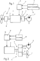
- auxiliary unit 1 shows a vehicle device with a Drive motor, not shown, for example an internal combustion engine and two auxiliary units 1 and 2 by a common electric motor 3 can be driven.
- auxiliary unit 1 can be, for example Act fan
- the internal combustion engine not shown cools if necessary.
- the auxiliary unit 2 can be a power steering pump, for example a device that builds up the operating pressure generated for the power steering of a motor vehicle. The management of the vehicle brings it along themselves that such auxiliary units are not permanent must be operated. For example shown that the fan only 20% of the Fanrzeug operating time must be put into operation and that only 10% to 30% of power steering assistance Travel time is needed.
- the electric motor 3 on one side a shaft connector 4 and on the other side has a shaft connector 5.
- the shaft connector 4, 5 are with a Freewheel 6 in connection, as a freewheel device 7 is formed and a first, clockwise Freewheel 8 and a second, left-turning Freewheel 9 owns.
- the shaft connector 4 is with the freewheel 8 and the shaft connector 5 with the Freewheel 9 in connection.
- the freewheel 8 in turn works with the first auxiliary unit 1 and the freewheel 9 together with the second auxiliary unit 2.
- the electric motor 3 is a control device 10 assigned their information from sensors 11, 12 receives.
- control device 10 it can for example, a very simple electrical Device, for example a switch or the like, but it is also possible that this is the control unit of the Motor vehicle, i.e. complex electronics, acts.
- the sensors 11, 12 monitor the operational management of the motor vehicle, in terms of Temperature and condition of the power steering system. If the temperature of the drive motor exceeds one certain value, the sensor 11 controls the Control device 10, which in turn then Electric motor 3 turns on, in such a way Direction of rotation that the freewheel 8 no Freewheel function, but a take-along function has, whereby the shaft connector 4 with the fan (Auxiliary unit 1) is connected and one appropriate cooling is brought about.
- FIG. 2 shows one corresponding to FIG. 1 Arrangement, however, the electric motor 3 only has a shaft connector 4, the two freewheels 8 and 9 drives simultaneously, the one freewheel 8 as right-hand freewheel and the other Freewheel 9 designed as a left-running freewheel is.
- This has the consequence that depending on the direction of rotation of the shaft connector 4 either the one freewheel, for example 8, in rotary driving function and the other Freewheel 9 is not in the rotational driving function or at another direction of rotation - the freewheel 9 in rotary driving function and the freewheel 8 does not have a rotary driving function occurs so that depending on the direction of rotation either the auxiliary unit 1 or the auxiliary unit 2 is actuated when the electric motor 3 is put into operation.
- FIG. 3 shows a further exemplary embodiment, in which the electric motor 3 with a freewheel 6 is connected by means of its shaft connector 4, wherein the freewheel 6 two switchable freewheels 14 and 15 has.
- the freewheels 14 and 15- the electric motor 3 with the Auxiliary unit 1, for example a fan, or with the auxiliary unit 2, for example a power steering pump, bring into rotation.
- the freewheels 14, 15 are of the control device 10 controlled that in the rotational entrainment of one Freewheel 14 or 15, the other freewheel 15 or 14, in non-turning driving located. This makes it possible to use the an electric motor 3 alternatively and preferably the auxiliary units 1 or interval 2 to operate.
- FIG. 4 shows one Structure in which the electric motor 3 permanently with the auxiliary unit 1 by means of the shaft connector 4 connected is.
- the freewheel 6 is designed such that - due to a control by the Control device 10- at the same time to operate the Auxiliary unit 1, the auxiliary unit 2 in operation can be taken. Therefore, the Freewheel 6, the auxiliary unit 2 with the shaft connector 4 by appropriate control in rotary driving bring. Of course, the turning takes place only if this is the operational management of the motor vehicle requires. Because at times from that Electric motor 3 two (or even more) auxiliary units operated, this is accordingly dimension.
- the electric motor 3 not only one, but several auxiliary units assigned are operated alternately or together, weight, installation space and costs are saved.
- the control device 10 For joint or alternative commissioning to be able to carry out the individual auxiliary units, it is only necessary to use the control device 10 provide the one hand the electric motor 3 switches on and off and on the other hand determines which ancillary unit when and when driving is not in rotary driving. To this Way two or more ancillary units use with a common electric motor 3.
- auxiliary units Preference is given to those auxiliary units that have approximately the same power requirement for Example 400 W for a power steering pump and 400 W for a radiator fan assigned to an electric motor 3, two opposing freewheels 8, 9 being provided are so that in one direction of rotation Power steering pump and in the other direction of rotation Radiator fan is driven. About the corresponding Signals from sensors 11 and 12 is decided whether “steering" or "cooling” by appropriate Direction of rotation of the electric motor 3 take place should. The aforementioned priority switching always ensures to ensure that the auxiliary unit is used first arrives that for a safe management is more important.
- the electric motor operates two ancillary units at the same time, with one permanently connected and the other one can be switched on if necessary for example an 800 for every 400 W of power required Use W electric motor.
Landscapes
- Engineering & Computer Science (AREA)
- Chemical & Material Sciences (AREA)
- Combustion & Propulsion (AREA)
- Transportation (AREA)
- Mechanical Engineering (AREA)
- Auxiliary Drives, Propulsion Controls, And Safety Devices (AREA)
- Control Of Multiple Motors (AREA)
Description
- Figur 1
- ein Prinzipschaltbild gemäß dem Ausführungsbeispiel einer ersten Fahrzeugeinrichtung,
- Figur 2
- ein weiteres Ausführungsbeispiel,
- Figur 3
- ein weiteres Ausführungsbeispiel und
- Figur 4
- ein letztes Ausführungsbeispiel.
Claims (10)
- Fahrzeugeinrichtung mit einem Antriebsmotor, insbesondere Verbrennungsmotor, dem mindestens zwei Nebenaggregate zugeordnet sind, wie beispielsweise eine Lenkhilfpumpe, ein Lüfter und/oder eine Anti-Blockiersystem-Pumpe usw., wobei der Antrieb der Nebenaggregate elektrisch und intervallartig nur dann erfolgt, wenn dies für die Betriebsführung erforderlich ist, dadurch gekennzeichnet, daß den Nebenaggregaten (1,2) ein einziger Elektromotor (3) zugeordnet ist und daß eines beziehungsweise mindestens eines der Nebenaggregate (1,2) mittels eines Freilaufs (6,8,9,14,15) zeitweise nicht in Drehmitnahme zum Elektromotor (3) steht.
- Fahrzeugeinrichtung nach Anspruch 1, dadurch gekennzeichnet, daß der Freilauf (6) eine Freilaufeinrichtung (7) ist, die in einer Drehrichtung eine Drehmitnahme und in der anderen Drehrichtung keine Drehmitnahme zwischen Elektromotor (3) und Nebenaggregat (1, 2) aufweist und daß der Elektromotor (3) drehrichtungsumschaltbar ausgebildet ist.
- Fahrzeugeinrichtung nach einem der vorhergehenden Ansprüche, dadurch gekennzeichnet, daß der Freilauf (6) ein schaltbarer Feilauf (14, 15) ist, der in einer Schaltstellung keine Drehmitnahme zwischen Elektromotor (3) und Nebenaggregat (1, 2) und in einer anderen Schaltstellung eine Drehmitnahme zwischen Elektromotor (3) und Nebenaggregat (1, 2) bewirkt.
- Fahrzeugeinrichtung nach einem der vorhergehenden Ansprüche, dadurch gekennzeichnet, daß der Elektromotor (3) beidseitig einen Wellenstutzen (4, 5) aufweist, wobei der eine Wellenstutzen (4) mit einem ersten, rechtsdrehenden Freilauf (8) und der zweite Wellenstutzen (5) mit einem zweiten, linksdrehenden Freilauf (9) in Verbindung steht und der erste Freilauf (8) mit einem ersten Nebenaggregat (1) und der zweite Freilauf (9) mit einem zweiten Nebenaggregat (2) verbunden ist.
- Fahrzeugeinrichtung nach einem der vorhergehenden Ansprüche, dadurch gekennzeichnet, daß ein Wellenstutzen (4) des Elektromotors (3) zwei Freiläufe (8, 9) antreibt, wobei der eine Freilauf (8) ein rechtsdrehender Freilauf und der andere Freilauf (9) ein linksdrehender Freilauf ist und die beiden Freiläufe (8, 9) jeweils mit einem Nebenaggregat (1, 2) verbunden sind.
- Fahrzeugeinrichtung nach einem der vorhergehenden Ansprüche, dadurch gekennzeichnet, daß ein Wellenstutzen (4) des Elektromotors (3) über mindestens zwei schaltbare Freiläufe (14, 15) mit mindestens zwei Nebenaggregaten (1, 2) derart betreibbar ist, daß sich einer der Freiläufe (14, 15) nicht in Drehmitnahme und der andere Freilauf (15, 14) in Drehmitnahme und umgekehrt befindet.
- Fahrzeugeinrichtung nach einem der vorhergehenden Ansprüche, dadurch gekennzeichnet, daß ein Wellenstutzen (4) des Elektromotors (3) permanent mit einem Nebenaggregat (1) verbunden ist und daß zusätzlich über mindestens einen schaltbaren Freilauf (14) mindestens ein weiteres Nebenaggregat (2) mit dem Elektromotor (3) verbindbar ist.
- Fahrzeugeinrichtung nach einem der vorhergehenden Ansprüche, dadurch gekennzeichnet, daß ein Anlassermotor des Antriebsmotors (Verbrennungsmotors) den Elektromotor (3) bildet.
- Fahrzeugeinrichtung nach einem der vorhergehenden Ansprüche, gekennzeichnet durch eine Steuereinrichtung (10) die das Ein- und Ausschalten des Elektromotors (3) vornimmt und die die Drehrichtungsänderung des Elektromotors (3) vorgibt und/oder der schaltbare Freilauf (14) beziehungsweise die schaltbaren Freiläufe (14, 15) nach Bedarf zum Betreiben der Nebenaggregate (1, 2) ansteuert.
- Fahrzeugeinrichtung nach einem der vorhergehenden Ansprüche, dadurch gekennzeichnet, daß die Steuereinrichtung (10) eine prioritätsschaltung (13) aufweist, die -nach der Wichtigkeit- entscheidet, welches Nebenaggregat (1, 2) zuerst betrieben werden soll beziehungsweise weiterbetrieben werden soll, wenn die Betriebsführung den gleichzeitigen Betrieb beider Nebenaggregate (1, 2) fordert.
Applications Claiming Priority (4)
| Application Number | Priority Date | Filing Date | Title |
|---|---|---|---|
| DE4416390 | 1994-05-09 | ||
| DE4416390 | 1994-05-09 | ||
| DE19514929A DE19514929A1 (de) | 1994-05-09 | 1995-04-22 | Fahrzeugeinrichtung mit einem Antriebsmotor und mindestens zwei Nebenaggregaten |
| DE19514929 | 1995-04-22 |
Publications (2)
| Publication Number | Publication Date |
|---|---|
| EP0681937A1 EP0681937A1 (de) | 1995-11-15 |
| EP0681937B1 true EP0681937B1 (de) | 1999-03-24 |
Family
ID=25936453
Family Applications (1)
| Application Number | Title | Priority Date | Filing Date |
|---|---|---|---|
| EP19950106877 Expired - Lifetime EP0681937B1 (de) | 1994-05-09 | 1995-05-06 | Fahrzeugeinrichtung mit einem Antriebsmotor und mindestens zwei Nebenaggregaten |
Country Status (2)
| Country | Link |
|---|---|
| EP (1) | EP0681937B1 (de) |
| JP (1) | JPH0840106A (de) |
Family Cites Families (1)
| Publication number | Priority date | Publication date | Assignee | Title |
|---|---|---|---|---|
| JPS5827590U (ja) * | 1981-08-18 | 1983-02-22 | 三菱電機株式会社 | 真空ポンプ |
-
1995
- 1995-05-06 EP EP19950106877 patent/EP0681937B1/de not_active Expired - Lifetime
- 1995-05-08 JP JP10974095A patent/JPH0840106A/ja active Pending
Also Published As
| Publication number | Publication date |
|---|---|
| EP0681937A1 (de) | 1995-11-15 |
| JPH0840106A (ja) | 1996-02-13 |
Similar Documents
| Publication | Publication Date | Title |
|---|---|---|
| DE3783638T2 (de) | Motorantriebsschaltung fuer zwei drehrichtungen. | |
| DE3785059T2 (de) | Geschwindigkeitssteuerung fuer ein scheibenwischersystem. | |
| DE69521586T2 (de) | Verfahren und Vorrichtung zur Regelung eines elektrischen Hilfskraft-Lenksystems mit einer zwei-dimensionalen Interpolation für Stromwerte | |
| DE60121898T2 (de) | Kraftfahrzeuglenksystem | |
| DE3525912C2 (de) | ||
| DE60303841T2 (de) | Fahrzeuglenkvorrichtung | |
| DE3617772C2 (de) | ||
| DE69312871T2 (de) | Elektrische Servolenkung | |
| DE102015213304A1 (de) | Elektromechanische Servolenkung | |
| DE3710591A1 (de) | Motorgetriebenes servolenkungssystem | |
| DE102005044899A1 (de) | Servolenkvorrichtung, welche durch einen Motor betrieben wird | |
| DE60310854T2 (de) | Steuerung einer elektrischen Servolenkung | |
| DE3819062C2 (de) | ||
| DE2008768A1 (de) | Steuersystem für elektrische Gleichstrommotoren | |
| DE102021117011B4 (de) | Force-Feedback-Aktuator für ein Steer-By-Wire-System und Verfahren zum Betrieb eines Force-Feedback-Aktuators für ein Steer-By-Wire-System | |
| EP0580997A1 (de) | Servolenkung eines Kraftfahrzeuges | |
| DE60121181T2 (de) | Verfahren und Vorrichtung zum Regeln von Lenkgefühl mit Diagnosen | |
| DE68913041T2 (de) | Fernsteuerung von Motorfunktionen. | |
| DE19514929A1 (de) | Fahrzeugeinrichtung mit einem Antriebsmotor und mindestens zwei Nebenaggregaten | |
| DE10025875A1 (de) | Lenksystem mit elektrischem Antrieb | |
| DE102021107894B4 (de) | Leistungsinduktivität mit nachgiebigen stiften und batterie-schnittstelle | |
| EP0681937A1 (de) | Fahrzeugeinrichtung mit einem Antriebsmotor und mindestens zwei Nebenaggregaten | |
| DE4300940B4 (de) | Betätigungsglied für eine Beschleunigungsvorrichtung | |
| DE102007013172A1 (de) | Lenkantriebssystem | |
| DE60107113T2 (de) | Verfahren zur steuerung eines wischermotors |
Legal Events
| Date | Code | Title | Description |
|---|---|---|---|
| PUAI | Public reference made under article 153(3) epc to a published international application that has entered the european phase |
Free format text: ORIGINAL CODE: 0009012 |
|
| AK | Designated contracting states |
Kind code of ref document: A1 Designated state(s): DE FR GB IT |
|
| 17P | Request for examination filed |
Effective date: 19951130 |
|
| 17Q | First examination report despatched |
Effective date: 19960926 |
|
| GRAG | Despatch of communication of intention to grant |
Free format text: ORIGINAL CODE: EPIDOS AGRA |
|
| GRAG | Despatch of communication of intention to grant |
Free format text: ORIGINAL CODE: EPIDOS AGRA |
|
| GRAH | Despatch of communication of intention to grant a patent |
Free format text: ORIGINAL CODE: EPIDOS IGRA |
|
| GRAH | Despatch of communication of intention to grant a patent |
Free format text: ORIGINAL CODE: EPIDOS IGRA |
|
| GRAA | (expected) grant |
Free format text: ORIGINAL CODE: 0009210 |
|
| AK | Designated contracting states |
Kind code of ref document: B1 Designated state(s): DE FR GB IT |
|
| REF | Corresponds to: |
Ref document number: 59505409 Country of ref document: DE Date of ref document: 19990429 |
|
| RAP2 | Party data changed (patent owner data changed or rights of a patent transferred) |
Owner name: LUK FAHRZEUG-HYDRAULIK GMBH & CO. KG |
|
| GBT | Gb: translation of ep patent filed (gb section 77(6)(a)/1977) |
Effective date: 19990524 |
|
| ET | Fr: translation filed | ||
| PLBE | No opposition filed within time limit |
Free format text: ORIGINAL CODE: 0009261 |
|
| STAA | Information on the status of an ep patent application or granted ep patent |
Free format text: STATUS: NO OPPOSITION FILED WITHIN TIME LIMIT |
|
| 26N | No opposition filed | ||
| REG | Reference to a national code |
Ref country code: GB Ref legal event code: IF02 |
|
| PGFP | Annual fee paid to national office [announced via postgrant information from national office to epo] |
Ref country code: FR Payment date: 20110607 Year of fee payment: 17 |
|
| PGFP | Annual fee paid to national office [announced via postgrant information from national office to epo] |
Ref country code: GB Payment date: 20110525 Year of fee payment: 17 |
|
| PGFP | Annual fee paid to national office [announced via postgrant information from national office to epo] |
Ref country code: DE Payment date: 20110601 Year of fee payment: 17 Ref country code: IT Payment date: 20110523 Year of fee payment: 17 |
|
| GBPC | Gb: european patent ceased through non-payment of renewal fee |
Effective date: 20120506 |
|
| PG25 | Lapsed in a contracting state [announced via postgrant information from national office to epo] |
Ref country code: IT Free format text: LAPSE BECAUSE OF NON-PAYMENT OF DUE FEES Effective date: 20120506 |
|
| REG | Reference to a national code |
Ref country code: FR Ref legal event code: ST Effective date: 20130131 |
|
| REG | Reference to a national code |
Ref country code: DE Ref legal event code: R119 Ref document number: 59505409 Country of ref document: DE Effective date: 20121201 |
|
| PG25 | Lapsed in a contracting state [announced via postgrant information from national office to epo] |
Ref country code: GB Free format text: LAPSE BECAUSE OF NON-PAYMENT OF DUE FEES Effective date: 20120506 Ref country code: FR Free format text: LAPSE BECAUSE OF NON-PAYMENT OF DUE FEES Effective date: 20120531 |
|
| PG25 | Lapsed in a contracting state [announced via postgrant information from national office to epo] |
Ref country code: DE Free format text: LAPSE BECAUSE OF NON-PAYMENT OF DUE FEES Effective date: 20121201 |