EP0680808A1 - Schlagwerkzeug mit Geschwindigkeitsregelschaltung - Google Patents
Schlagwerkzeug mit Geschwindigkeitsregelschaltung Download PDFInfo
- Publication number
- EP0680808A1 EP0680808A1 EP95302725A EP95302725A EP0680808A1 EP 0680808 A1 EP0680808 A1 EP 0680808A1 EP 95302725 A EP95302725 A EP 95302725A EP 95302725 A EP95302725 A EP 95302725A EP 0680808 A1 EP0680808 A1 EP 0680808A1
- Authority
- EP
- European Patent Office
- Prior art keywords
- speed
- motor
- trigger
- potentiometer
- speed control
- Prior art date
- Legal status (The legal status is an assumption and is not a legal conclusion. Google has not performed a legal analysis and makes no representation as to the accuracy of the status listed.)
- Granted
Links
Images
Classifications
-
- B—PERFORMING OPERATIONS; TRANSPORTING
- B25—HAND TOOLS; PORTABLE POWER-DRIVEN TOOLS; MANIPULATORS
- B25B—TOOLS OR BENCH DEVICES NOT OTHERWISE PROVIDED FOR, FOR FASTENING, CONNECTING, DISENGAGING OR HOLDING
- B25B3/00—Hand vices, i.e. vices intended to be held by hand; Pin vices
-
- H—ELECTRICITY
- H02—GENERATION; CONVERSION OR DISTRIBUTION OF ELECTRIC POWER
- H02P—CONTROL OR REGULATION OF ELECTRIC MOTORS, ELECTRIC GENERATORS OR DYNAMO-ELECTRIC CONVERTERS; CONTROLLING TRANSFORMERS, REACTORS OR CHOKE COILS
- H02P7/00—Arrangements for regulating or controlling the speed or torque of electric DC motors
- H02P7/06—Arrangements for regulating or controlling the speed or torque of electric DC motors for regulating or controlling an individual dc dynamo-electric motor by varying field or armature current
- H02P7/18—Arrangements for regulating or controlling the speed or torque of electric DC motors for regulating or controlling an individual dc dynamo-electric motor by varying field or armature current by master control with auxiliary power
- H02P7/24—Arrangements for regulating or controlling the speed or torque of electric DC motors for regulating or controlling an individual dc dynamo-electric motor by varying field or armature current by master control with auxiliary power using discharge tubes or semiconductor devices
- H02P7/28—Arrangements for regulating or controlling the speed or torque of electric DC motors for regulating or controlling an individual dc dynamo-electric motor by varying field or armature current by master control with auxiliary power using discharge tubes or semiconductor devices using semiconductor devices
- H02P7/285—Arrangements for regulating or controlling the speed or torque of electric DC motors for regulating or controlling an individual dc dynamo-electric motor by varying field or armature current by master control with auxiliary power using discharge tubes or semiconductor devices using semiconductor devices controlling armature supply only
- H02P7/29—Arrangements for regulating or controlling the speed or torque of electric DC motors for regulating or controlling an individual dc dynamo-electric motor by varying field or armature current by master control with auxiliary power using discharge tubes or semiconductor devices using semiconductor devices controlling armature supply only using pulse modulation
-
- B—PERFORMING OPERATIONS; TRANSPORTING
- B25—HAND TOOLS; PORTABLE POWER-DRIVEN TOOLS; MANIPULATORS
- B25B—TOOLS OR BENCH DEVICES NOT OTHERWISE PROVIDED FOR, FOR FASTENING, CONNECTING, DISENGAGING OR HOLDING
- B25B23/00—Details of, or accessories for, spanners, wrenches, screwdrivers
- B25B23/14—Arrangement of torque limiters or torque indicators in wrenches or screwdrivers
- B25B23/147—Arrangement of torque limiters or torque indicators in wrenches or screwdrivers specially adapted for electrically operated wrenches or screwdrivers
- B25B23/1475—Arrangement of torque limiters or torque indicators in wrenches or screwdrivers specially adapted for electrically operated wrenches or screwdrivers for impact wrenches or screwdrivers
-
- H—ELECTRICITY
- H02—GENERATION; CONVERSION OR DISTRIBUTION OF ELECTRIC POWER
- H02P—CONTROL OR REGULATION OF ELECTRIC MOTORS, ELECTRIC GENERATORS OR DYNAMO-ELECTRIC CONVERTERS; CONTROLLING TRANSFORMERS, REACTORS OR CHOKE COILS
- H02P7/00—Arrangements for regulating or controlling the speed or torque of electric DC motors
Definitions
- This invention relates to electrical impact tools, and more particularly to an electrical, variable speed impact tool having an operator settable maximum speed control for enabling the operator to controllably limit the maximum speed, and thus the maximum torque, of the tool.
- Impact tools are used in a wide variety of applications to quickly secure various forms of fasteners such as threaded screws, nuts and the like to a work surface.
- Such impact tools typically include an operator-engageable trigger which is electrically coupled to a speed control circuit disposed within a housing of the impact tool.
- the speed control circuit is in turn electrically coupled to a motor of the impact tool and provides a variable voltage drive signal to the motor in accordance with the degree of engagement of the trigger by the operator. In this manner the speed of the motor, and thus the torque which is applied by the motor to drive a threaded screw or other like fastener, can be controlled by the operator simply by varying the degree of engagement of the trigger.
- a variable speed impact tool comprising a drive motor; a means for forming a speed control circuit for controlling the speed of the motor; a trigger engageable by an operator and operably coupled to the means for forming a speed control circuit to allow the operator to generate a speed control signal based on the degree of actuation of the trigger; characterised by a means adjustable by the operator and in communication with the means for forming a speed control circuit for enabling the operator to set a first maximum speed at which the motor can be driven when the trigger is fully engaged.
- the operator settable speed limiting control enables the operator to limit the maximum speed at which the tool may be operated to a desired percentage of the maximum motor speed, regardless of the degree of engagement of a trigger of the tool during use.
- the speed control circuit is electrically responsive to the degree of engagement of the trigger such that the greater the degree of engagement of the trigger by the operator the greater the speed at which the motor is driven by the speed control circuit.
- the speed control circuit is further electrically responsive to an operator settable speed control limiting circuit having an operator adjustable speed limiting control preferably readily accessible by the operator without any disassembly of the tool.
- the operator accessible speed limiting control enables the operator to limit the maximum motor speed at which the tool may be operated to a desired percentage of full motor speed when the trigger is fully engaged.
- the speed control limiting circuit causes the motor speed to be limited to the operator adjusted percentage of the maximum motor speed, thus limiting the torque applied by the tool.
- a timer circuit and preferably a conventional CMOS timer circuit, may be used as the motor speed control circuit.
- CMOS timer circuit a bipolar transistor timer could also be used in lieu of a CMOS timer.
- the CMOS timer circuit generates a pulse-width-modulated like voltage drive signal and is electrically responsive to the trigger of the impact tool such that the duty cycle of the voltage drive signal is variable in response to the degree of engagement of the trigger.
- the speed control limiting circuit preferably comprises a potentiometer which is readily manually adjustable by the operator. The potentiometer operates to limit the maximum duty cycle of the voltage drive signal from the CMOS timer circuit to cause the motor speed to be limited to a predetermined percentage of its maximum speed. Thus, for example, if the speed control limiting circuit is adjusted by the operator to limit the motor speed to 75 percent of the maximum motor speed, the motor speed, and thus the torque generated by the motors will be limited to this percentage when the trigger of the tool is engaged completely by the operator during use. Thus, there is little or no chance of the operator "over-driving" a fastener and thus breaking the fastener, by inadvertently and momentarily applying too much pressure to the trigger of the tool during use.
- the apparatus of the present invention provides an impact tool having a uniquely simple and relatively inexpensive means by which the maximum speed of the motor of the tool may be controllably limited by the operator without adding significant cost or complexity to the impact tool.
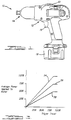
- the impact tool 10 includes a housing 12 which includes a motor (not shown) and a speed control circuit, which will be discussed momentarily in connection with Figure 2.
- the motor is mechanically coupled to a tool bit holder 14 via a suitable, conventional gear reduction system and impacting mechanism (not shown).
- the speed control circuit is also electrically coupled to a manually engageable trigger 16. As the operator squeezes the trigger 16, the motor speed is increased generally linearly in accordance with the degree to which the operator squeezes and holds the trigger 16 engaged.
- the motor speed control circuit causes a voltage drive signal to be applied to the motor which causes the motor to be driven at a speed which is approximately 50% of its maximum speed.
- Full engagement of the trigger 16 causes a maximum voltage drive signal to be applied to the motor which causes the motor to be driven at its maximum rotational speed.
- a rechargeable battery pack 18 is included for powering the motor. It will be appreciated, however, that while the impact tool 10 of the present invention has been illustrated as being a battery powered impact tool, that the impact tool 10 could easily be adapted with minor modifications for use with an A/C power source.
- the impact tool 10 of Figure 1 further includes a rotatable speed limiting control 20 which is mechanically coupled to the speed limiting control circuit disposed within the housing 12.
- the speed limiting control 20 may be easily and conveniently adjusted by the operator with a single hand to limit the maximum speed of the motor, and thus the maximum torque generated by the motor, as will be described in more detail in connection with Figure 2. Once sat in a certain position, however, the speed limiting control 20 remains at that position until the operator readjusts it.
- the impact tool 10 includes suitable indicia on the housing 12 closely adjacent the speed limiting control 20 to provide an immediate visual indication of the degree of speed reduction that a given setting of the control 20 provides.
- This indicia may correspond to percentages (i.e., 25%, 50%, etc.) of the maximum motor speed, single digits (e.g., "1" through "5") denoting various levels of maximum motor speed, or virtually any other designation which readily identifies the degree of speed reduction that a given setting of the speed limiting control 20 provides.
- the control 20 has been illustrated in Figure 1 as being on a top portion of the housing 12, that it could be disposed at other locations on the housing 12, such as a side portion, if so desired.
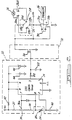
- FIG. 2 an electrical circuit diagram is shown illustrating the speed control circuit, which is denoted by reference numeral 22, in electrical communication with a speed limiting circuit 24 of the present invention. Also shown is the motor, designated by reference numeral 26, and a directional switch 28 for reversing direction of the motor 26.
- the trigger 16 has also been illustrated in simplified form and shown as coupled to a brake contact switch 30 for braking the motor 26 when the trigger 16 is completely released by the operator.
- FET field effect transistor
- the speed control circuit 22 comprises a timer circuit 34 which, in the preferred embodiment, is represented by a 555 CMOS timer circuit.
- Pin 7 of this circuit is a DISCHARGE input which is electrically coupled to the wiper arm 36a of a speed control potentiometer 36.
- the wiper arm 36a is also mechanically coupled to the trigger 16 such that engagement of the trigger 16 causes a corresponding movement of the wiper arm 36a.
- the potentiometer 36 is also coupled to supply voltage (V+) through a resistor 37.
- Pin 6 of the CMOS timer circuit 34 is a THRESHOLD input to an internal comparator of the circuit which is coupled to one side of the speed control limiting circuit 24 and a resistor 38.
- the speed control limiting circuit 24 is comprised of a potentiometer having its wiper arm 24a coupled to the speed limiting control 20 ( Figure 1).
- rotational movement of the control 20 causes a corresponding movement of the wiper arm 24a of the potentiometer 24.
- pin 2 of the timer circuit 34 is coupled to the opposite side of the potentiometer 24 and to a capacitor 40.
- Pin 8 of the timer circuit 34 is coupled through a resistor 42 to the supply voltage (V+).
- Pin 4 is a RESET input which is coupled to a capacitor 44, a zener diode 46, and also to the resistor 42.
- the zener diode 46 provides protection to the timer circuit 34 in the event of a voltage transient and limits the supply voltage to a predetermined level, which in the preferred embodiment is about 9.1 V dc.
- Pin 3 of the timer circuit 34 is coupled to a resistor 48, which is in turn coupled to the gate 50 of the FET 32 and also to a capacitor 52.
- the timer circuit 34 is controlled by the charging and discharging cycles of the capacitor 40, the charging cycle of which is affected by the settings of the speed limiting potentiometer 24 and the speed control potentiometer 36.
- the capacitor 40 When the capacitor 40 is discharged below to a value of approximately 33% of the supply voltage (V+), the input to pin 2 of the timer circuit 34 will cause the internal comparator to generate a high level logic signal output at pin 3 which is applied to the gate 50 of the FET 32. This causes the FET 32 to be turned on.
- a second internal comparator of the timer circuit 34 causes the output at pin 3 to go to a logic low level signal, which in turn causes the PET 32 to be turned off. Simultaneously, an internal discharge transistor of the timer circuit 34 is turned on which couples pin 7 (DISCHARGE) to ground. The capacitor 40 then discharges through the potentiometers 24 and 36, the resistor 38 and pin 7 of the timer circuit 34. The resulting output at pin 3 of the timer circuit 34 is a rectangular-wave output signal.
- the speed limiting potentiometer 24 is set to its minimum resistance (approximately zero ohms)
- varying the resistance of the speed control potentiometer 36 thus increases or decreases the discharging time for the capacitor 40. This in turn varies the duration during which the signal from pin 3 of the timer circuit 34 is at a logic high level and consequently controls the duty cycle of the PET 32.
- the duty cycle determines the "average" power applied to the motor 26.
- the potentiometer 24 is set to provide its minimum resistance, the capacitor 40 will be discharged most rapidly. This in turn causes the output at pin 3 to more quickly reach the 33% plateau at which the timer circuit 34 turns on the FET 32.
- the discharging time of the capacitor 40 can be further controlled to limit the maximum duty cycle of the FET 32, and thus the maximum average voltage applied to the motor 26 to a user defined percentage of the maximum voltage capable of being applied to the motor 26.
- the speed limiting potentiometer 24 is set to provide some value of additional resistance, the RC time constant will be lengthened. The capacitor 40 will therefore discharge at a slower rate than it would otherwise discharge at for any given setting of the speed control potentiometer 36, thus further limiting the maximum duty cycle of the PET 32, and thus the maximum average voltage applied to the motor 26.
- the speed limiting potentiometer 24 When the speed limiting potentiometer 24 is set to its minimum resistance value (approximately zero ohms), it will have virtually no effect on the discharging time of the capacitor 40, and thus no effect on the duty cycle of the FET 32. In this instance the duty cycle of the PET 32 is controlled entirely by the setting of the speed control potentiometer 36 through engagement of the trigger 16.
- the speed limiting potentiometer 24 allows the operator to controllably limit the maximum duty cycle of the PET 32 , and thus the maximum average voltage applied to the motor 26. This in turn limits the maximum torque which the motor 26 produces when the trigger 16 is fully engaged to a corresponding percentage of the maximum torque that would otherwise be produced by the motor 16 with full engagement of the trigger 16.
- the operator sets the speed limiting control 20 to a desired position corresponding to the percentage of the maximum motor speed which he desires to limit the impact tool 10 to.
- the speed limiting control 20 has been set to 75% of the maximum motor speed.
- the brake contact switch 30 is immediately opened and power contacts 31a and 31b are electrically coupled.
- the wiper 36a of the potentiometer 36 is adjusted as the capacitor 40 begins to charge in series through resistors 37 and 38 and the potentiometers 36 and 24.
- the forward/reverse switch 28 is moved to the reverse switch, then the terminals 28a and 28b will be electrically coupled and terminals 28c and 28d will be electrically coupled.
- the direction of current flow through the motor 26 can be controlled to cause forward and reverse operation of the motor 26.
- the speed control limiting potentiometer 24 provides a simple, inexpensive, yet effective means for enabling a user of the impact tool 10 to quickly and easily limit the maximum motor speed, and thus the maximum torque, which can be produced by the impact tool 10 to avoid inadvertently breaking fasteners during use of the impact tool 10.
- the speed control limiting potentiometer 24 thus allows individuals with limited experience in using impact tools, or individuals who do not use impact tools regularly enough to develop the necessary "feel" for operating the trigger 16 to avoid breaking fasteners, to still use the tool 10 conveniently without over tightening fasteners to a degree which causes breakage.
- the speed limiting control potentiometer 24 of the present invention can further be implemented with a minimum degree of expense in circuit modifications to many existing forms of speed control circuits without adding appreciably to the overall cost of the impact tool or to the complexity of its assembly.
- a fastener such as a screw may be driven with a bit mounted in holder 14.
- a fastener such as a nut may be driven with a socket mounted in holder 14 or mounted directly an the output spindle of the tool.
Landscapes
- Engineering & Computer Science (AREA)
- Mechanical Engineering (AREA)
- Power Engineering (AREA)
- Control Of Electric Motors In General (AREA)
- Details Of Spanners, Wrenches, And Screw Drivers And Accessories (AREA)
- Control Of Direct Current Motors (AREA)
Applications Claiming Priority (2)
| Application Number | Priority Date | Filing Date | Title |
|---|---|---|---|
| US232559 | 1994-04-25 | ||
| US08/232,559 US5526460A (en) | 1994-04-25 | 1994-04-25 | Impact wrench having speed control circuit |
Publications (2)
| Publication Number | Publication Date |
|---|---|
| EP0680808A1 true EP0680808A1 (de) | 1995-11-08 |
| EP0680808B1 EP0680808B1 (de) | 2001-08-29 |
Family
ID=22873630
Family Applications (1)
| Application Number | Title | Priority Date | Filing Date |
|---|---|---|---|
| EP95302725A Expired - Lifetime EP0680808B1 (de) | 1994-04-25 | 1995-04-24 | Schlagwerkzeug mit Geschwindigkeitsregelschaltung |
Country Status (7)
| Country | Link |
|---|---|
| US (1) | US5526460A (de) |
| EP (1) | EP0680808B1 (de) |
| JP (1) | JPH08132353A (de) |
| KR (1) | KR950035018A (de) |
| AU (1) | AU684147B2 (de) |
| CA (1) | CA2147735A1 (de) |
| DE (1) | DE69522363D1 (de) |
Cited By (13)
| Publication number | Priority date | Publication date | Assignee | Title |
|---|---|---|---|---|
| EP0808018A1 (de) * | 1996-05-13 | 1997-11-19 | Black & Decker Inc. | Elektrowerkzeug mit einer Motorsteuerungsschaltung zur Verbesserung der Steuerung der Drehmomentsabgabe des Elektrowerkzeuges |
| FR2771866A1 (fr) * | 1997-12-03 | 1999-06-04 | Ecia Equip Composants Ind Auto | Systeme de commande de l'alimentation d'un moteur electrique d'activation d'un organe fonctionnel de vehicule automobile |
| EP1120200A2 (de) * | 2000-01-28 | 2001-08-01 | Nitto Kohki Co., Ltd. | Schlagschraubendreher der drehmoment-überwachten Art |
| US6424799B1 (en) | 1993-07-06 | 2002-07-23 | Black & Decker Inc. | Electrical power tool having a motor control circuit for providing control over the torque output of the power tool |
| WO2004012607A2 (en) * | 2002-08-01 | 2004-02-12 | Stryker Corporation | Cordless, powered surgical tool |
| NL1028779C2 (nl) * | 2005-04-15 | 2006-10-17 | Electrische App Nfabriek Capax | Regelschakeling voor het regelen van het aan een elektromotor toegevoerde vermogen met beperking van het regelgebied. |
| US7137541B2 (en) | 2004-04-02 | 2006-11-21 | Black & Decker Inc. | Fastening tool with mode selector switch |
| US7285877B2 (en) | 2004-04-02 | 2007-10-23 | Black & Decker Inc. | Electronic fastening tool |
| WO2009136840A1 (en) * | 2008-05-08 | 2009-11-12 | Atlas Copco Tools Ab | Method and device for tightening joints |
| US7646157B2 (en) | 2007-03-16 | 2010-01-12 | Black & Decker Inc. | Driving tool and method for controlling same |
| US8347978B2 (en) | 2004-04-02 | 2013-01-08 | Black & Decker Inc. | Method for controlling a power driver |
| US8408327B2 (en) | 2004-04-02 | 2013-04-02 | Black & Decker Inc. | Method for operating a power driver |
| CN106208655A (zh) * | 2016-08-31 | 2016-12-07 | 武汉烽火网络有限责任公司 | 一种低压直流电源可靠接入装置 |
Families Citing this family (62)
| Publication number | Priority date | Publication date | Assignee | Title |
|---|---|---|---|---|
| US5657417A (en) * | 1995-05-02 | 1997-08-12 | Burndy Corporation | Control for battery powered tool |
| JP3106944B2 (ja) * | 1996-01-22 | 2000-11-06 | 松下電器産業株式会社 | 消耗電極式ア−ク溶接機 |
| US5963707A (en) * | 1996-04-23 | 1999-10-05 | Kc Multi-Ring Products, Inc. | Method and apparatus for determining and adjusting torque in an electric impact torque wrench |
| USRE38486E1 (en) * | 1997-03-04 | 2004-04-06 | Makita Corporation | Electric motor control circuit |
| US6448676B1 (en) | 1999-05-18 | 2002-09-10 | Siemens Automotive Inc. | Pulse width modulated engine cooling fan motor with integrated MOSFET |
| US6732449B2 (en) | 2000-09-15 | 2004-05-11 | Walter Evanyk | Dryer/blower appliance with efficient waste heat dissipation |
| US6891130B2 (en) * | 2000-09-15 | 2005-05-10 | Walter Evanyk | Appliance for dispensing melt adhesive with variable duty cycle and method of implementing |
| US6946623B2 (en) * | 2000-09-15 | 2005-09-20 | Powerpulse Technologies, L.P. | Appliance for liquefying solder with variable duty cycle and method of implementing |
| US6733414B2 (en) | 2001-01-12 | 2004-05-11 | Milwaukee Electric Tool Corporation | Gear assembly for a power tool |
| US6508313B1 (en) * | 2001-07-23 | 2003-01-21 | Snap-On Technologies, Inc. | Impact tool battery pack with acoustically-triggered timed impact shutoff |
| US20060098380A1 (en) * | 2002-07-24 | 2006-05-11 | Boucher Craig J | Timer-controlled clamp for initiation elements |
| GB2409833B (en) * | 2002-10-16 | 2006-09-13 | Snap On Tools Corp | Ratcheting torque-angle wrench and method |
| DE20305224U1 (de) * | 2003-03-31 | 2003-06-05 | Hilti Ag | Handwerkzeug mit Funktionsstufenanzeige |
| US6749028B1 (en) * | 2003-05-22 | 2004-06-15 | Defond Components Limited | Power tool trigger assembly |
| US7492125B2 (en) * | 2004-11-04 | 2009-02-17 | Milwaukee Electric Tool Corporation | Power tools, battery chargers and batteries |
| US20060112570A1 (en) * | 2004-11-04 | 2006-06-01 | Serdynski David P | Power tools, battery chargers and batteries |
| FR2893270B1 (fr) * | 2005-11-15 | 2010-01-15 | Renault Georges Ets | Cle a serrage discontinu comprenant des moyens de mesure de phenomenes dynamiques induits par ledit serrage sur le carter de la cle |
| US8903577B2 (en) | 2009-10-30 | 2014-12-02 | Lsi Industries, Inc. | Traction system for electrically powered vehicles |
| US7598683B1 (en) | 2007-07-31 | 2009-10-06 | Lsi Industries, Inc. | Control of light intensity using pulses of a fixed duration and frequency |
| US8604709B2 (en) | 2007-07-31 | 2013-12-10 | Lsi Industries, Inc. | Methods and systems for controlling electrical power to DC loads |
| WO2009038230A1 (en) * | 2007-09-21 | 2009-03-26 | Hitachi Koki Co., Ltd. | Impact tool |
| US7717192B2 (en) | 2007-11-21 | 2010-05-18 | Black & Decker Inc. | Multi-mode drill with mode collar |
| US7798245B2 (en) | 2007-11-21 | 2010-09-21 | Black & Decker Inc. | Multi-mode drill with an electronic switching arrangement |
| US7717191B2 (en) | 2007-11-21 | 2010-05-18 | Black & Decker Inc. | Multi-mode hammer drill with shift lock |
| US7735575B2 (en) | 2007-11-21 | 2010-06-15 | Black & Decker Inc. | Hammer drill with hard hammer support structure |
| US7854274B2 (en) | 2007-11-21 | 2010-12-21 | Black & Decker Inc. | Multi-mode drill and transmission sub-assembly including a gear case cover supporting biasing |
| US7770660B2 (en) | 2007-11-21 | 2010-08-10 | Black & Decker Inc. | Mid-handle drill construction and assembly process |
| US7762349B2 (en) | 2007-11-21 | 2010-07-27 | Black & Decker Inc. | Multi-speed drill and transmission with low gear only clutch |
| TW200948544A (en) * | 2008-05-16 | 2009-12-01 | Mobiletron Electronics Co Ltd | Torque control circuit of electric hammer type screw wrench |
| DE102009045183A1 (de) * | 2009-08-19 | 2011-02-24 | Robert Bosch Gmbh | Scheibenwischvorrichtung |
| US9475180B2 (en) | 2010-01-07 | 2016-10-25 | Black & Decker Inc. | Power tool having rotary input control |
| US9266178B2 (en) | 2010-01-07 | 2016-02-23 | Black & Decker Inc. | Power tool having rotary input control |
| US8418778B2 (en) | 2010-01-07 | 2013-04-16 | Black & Decker Inc. | Power screwdriver having rotary input control |
| CN102259329B (zh) | 2011-06-22 | 2013-08-21 | 南京德朔实业有限公司 | 多功能电动工具 |
| US9364942B2 (en) | 2011-06-24 | 2016-06-14 | Black & Decker Inc. | Quick release socket attachment for impact wrench |
| US20130192860A1 (en) | 2011-06-24 | 2013-08-01 | Black & Decker Inc. | Electromagnetic mode change mechanism for power tool |
| US8493172B2 (en) * | 2011-09-30 | 2013-07-23 | Snap-On Incorporated | Variable speed toggle trigger |
| WO2015061370A1 (en) | 2013-10-21 | 2015-04-30 | Milwaukee Electric Tool Corporation | Adapter for power tool devices |
| AU2014201922B1 (en) * | 2014-04-03 | 2015-01-22 | Techway Industrial Co., Ltd. | Torque control device for electrical hand tools |
| US10637379B2 (en) * | 2015-04-07 | 2020-04-28 | Black & Decker Inc. | Power tool with automatic feathering mode |
| US10357871B2 (en) | 2015-04-28 | 2019-07-23 | Milwaukee Electric Tool Corporation | Precision torque screwdriver |
| CN208729640U (zh) | 2015-04-28 | 2019-04-12 | 米沃奇电动工具公司 | 一种旋转动力工具和用于其的换能器组件 |
| US10603770B2 (en) | 2015-05-04 | 2020-03-31 | Milwaukee Electric Tool Corporation | Adaptive impact blow detection |
| US10295990B2 (en) | 2015-05-18 | 2019-05-21 | Milwaukee Electric Tool Corporation | User interface for tool configuration and data capture |
| WO2016196979A1 (en) | 2015-06-05 | 2016-12-08 | Ingersoll-Rand Company | Impact tools with ring gear alignment features |
| US11260517B2 (en) | 2015-06-05 | 2022-03-01 | Ingersoll-Rand Industrial U.S., Inc. | Power tool housings |
| WO2016196905A1 (en) | 2015-06-05 | 2016-12-08 | Ingersoll-Rand Company | Lighting systems for power tools |
| WO2016196918A1 (en) | 2015-06-05 | 2016-12-08 | Ingersoll-Rand Company | Power tool user interfaces |
| WO2016196984A1 (en) | 2015-06-05 | 2016-12-08 | Ingersoll-Rand Company | Power tools with user-selectable operational modes |
| WO2016196891A1 (en) | 2015-06-05 | 2016-12-08 | Ingersoll-Rand Company | Power tool user interfaces |
| TWI576213B (zh) * | 2015-11-10 | 2017-04-01 | 豐民金屬工業股份有限公司 | 電動衝擊式工具之扭力控制裝置及其方法 |
| TWM545024U (zh) | 2016-01-05 | 2017-07-11 | 米沃奇電子工具公司 | 用於電動工具的減震系統 |
| AU2017213819B2 (en) | 2016-02-03 | 2019-12-05 | Milwaukee Electric Tool Corporation | Systems and methods for configuring a reciprocating saw |
| USD789170S1 (en) | 2016-02-05 | 2017-06-13 | Tti (Macao Commercial Offshore) Limited | Rotary power tool |
| AU2017223863B2 (en) | 2016-02-25 | 2019-12-19 | Milwaukee Electric Tool Corporation | Power tool including an output position sensor |
| EP3765226B1 (de) | 2018-03-16 | 2023-11-01 | Milwaukee Electric Tool Corporation | Klingenklemme für elektrowerkzeug, hin- und herbewegbares kraftwerkzeug und verfahren zum betrieb einer solchen klingenklemme |
| WO2019194987A1 (en) | 2018-04-03 | 2019-10-10 | Milwaukee Electric Tool Corporation | Jigsaw |
| USD887806S1 (en) | 2018-04-03 | 2020-06-23 | Milwaukee Electric Tool Corporation | Jigsaw |
| IL266295B2 (en) | 2019-04-28 | 2024-02-01 | Ham Let Israel Canada Ltd | key |
| EP4263138A1 (de) | 2020-12-18 | 2023-10-25 | Black & Decker Inc. | Schlagwerkzeuge und steuerungsmodi |
| DE102021110411A1 (de) * | 2021-04-23 | 2022-10-27 | HELLA GmbH & Co. KGaA | Verfahren zur Herstellung einer Schraubverbindung |
| CN114115203B (zh) * | 2022-01-27 | 2022-05-10 | 天津德科智控股份有限公司 | 一种eps用基于ne555设计的模拟扭矩传感器 |
Citations (9)
| Publication number | Priority date | Publication date | Assignee | Title |
|---|---|---|---|---|
| DE3103286A1 (de) * | 1981-01-31 | 1982-08-12 | Kress-elektrik GmbH & Co, Elektromotorenfabrik, 7457 Bisingen | Elektrohandwerkzeugmaschine zum schrauben, bohren und eventuell schlagbohren |
| EP0076039A1 (de) * | 1981-08-31 | 1983-04-06 | Capax Electrische Apparatenfabriek B.V. | Drehzahlsteuerung für Elektrokraftwerkzeuge mit einem Gleichstrommotor |
| US4856078A (en) * | 1988-03-23 | 1989-08-08 | Zenith Electronics Corporation | DC fan speed control |
| GB2217480A (en) * | 1988-04-16 | 1989-10-25 | Bosch Gmbh Robert | Speed setting for electric hand tool |
| US4998589A (en) * | 1990-02-26 | 1991-03-12 | Wiesendanger John A | Variable speed drill control cam apparatus |
| US5014793A (en) * | 1989-04-10 | 1991-05-14 | Measurement Specialties, Inc. | Variable speed DC motor controller apparatus particularly adapted for control of portable-power tools |
| JPH04208097A (ja) * | 1990-11-30 | 1992-07-29 | Omron Corp | 直流モータ制御回路 |
| WO1993014559A1 (en) * | 1992-01-21 | 1993-07-22 | Nartron Corporation | Pulse width modulation power circuit |
| EP0633095A1 (de) * | 1993-07-06 | 1995-01-11 | Emhart Inc. | Elektrisch betriebenes Werkzeug |
Family Cites Families (20)
| Publication number | Priority date | Publication date | Assignee | Title |
|---|---|---|---|---|
| US3665493A (en) * | 1970-03-30 | 1972-05-23 | Bendix Corp | Adaptive numerical control system for a machine tool |
| US3710213A (en) * | 1971-02-22 | 1973-01-09 | Cutler Hammer Inc | Pulse rate control motor speed control system with feedback |
| GB1413476A (en) * | 1971-11-10 | 1975-11-12 | Cav Ltd | Speed control for dc motors |
| US3875486A (en) * | 1973-10-12 | 1975-04-01 | William J Barton | Motor speed control circuit |
| DE2629722C3 (de) * | 1976-07-02 | 1981-04-23 | Scintilla Ag, Solothurn | Handbetätigbare Einbauschaltvorrichtung für elektrische Maschinen, insbesondere Handbohrmaschinen |
| US4233549A (en) * | 1978-12-08 | 1980-11-11 | Baxter Travenol Laboratories, Inc. | Speed and torque control for fractional horsepower motors |
| US4412158A (en) * | 1980-02-21 | 1983-10-25 | Black & Decker Inc. | Speed control circuit for an electric power tool |
| JPS58103892A (ja) * | 1981-12-16 | 1983-06-21 | Hitachi Ltd | トランジスタチヨツパ制御装置 |
| DE3329971A1 (de) * | 1983-08-19 | 1985-03-07 | Robert Bosch Gmbh, 7000 Stuttgart | Steuer- und bedienvorrichtung fuer ein elektrisches handwerkzeug |
| DE3342412A1 (de) * | 1983-11-24 | 1985-06-05 | Black & Decker Inc., Newark, Del. | Schalteranordnung fuer den drehrichtungsumschalter eines elektrowerkzeugs, insbesondere einer bohr- oder schlagbohrmaschine |
| DE3443670A1 (de) * | 1984-11-30 | 1986-06-05 | C. & E. Fein Gmbh & Co, 7000 Stuttgart | Kraftgetriebene schraubvorrichtung mit variabler drehmomenteinstellung |
| US4734629A (en) * | 1985-08-09 | 1988-03-29 | Black & Decker Inc. | Variable speed trigger switch |
| US4841165A (en) * | 1988-02-12 | 1989-06-20 | Wesley H. Heinmiller | D. C. power controller |
| JPH01291686A (ja) * | 1988-05-14 | 1989-11-24 | Matsushita Electric Works Ltd | 電動工具 |
| US5015928A (en) * | 1988-06-03 | 1991-05-14 | Yang Tai Her | Universal series motor with speed limiting circuit to protect the motor from overspeeding during relatively-small loads |
| JPH02167678A (ja) * | 1988-12-16 | 1990-06-28 | Nippon Electric Ind Co Ltd | スピード・コントロール付電動インパクトレンチ |
| US5254913A (en) * | 1991-08-14 | 1993-10-19 | Yang Tai Her | Speed limiting circuit for universal type series or compound electric motor |
| JPH05220677A (ja) * | 1992-02-10 | 1993-08-31 | Matsushita Electric Works Ltd | 電動工具の保護装置 |
| ES2101811T3 (es) * | 1992-10-28 | 1997-07-16 | Yang Tai Her | Circuito regulador para motor universal en serie (o compound). |
| US5414793A (en) * | 1993-04-27 | 1995-05-09 | Ryobi Motor Products Corp. | Speed control mechanism for a power tool |
-
1994
- 1994-04-25 US US08/232,559 patent/US5526460A/en not_active Expired - Lifetime
-
1995
- 1995-04-24 CA CA002147735A patent/CA2147735A1/en not_active Abandoned
- 1995-04-24 DE DE69522363T patent/DE69522363D1/de not_active Expired - Lifetime
- 1995-04-24 AU AU17646/95A patent/AU684147B2/en not_active Ceased
- 1995-04-24 EP EP95302725A patent/EP0680808B1/de not_active Expired - Lifetime
- 1995-04-25 JP JP7101188A patent/JPH08132353A/ja not_active Withdrawn
- 1995-04-25 KR KR1019950009700A patent/KR950035018A/ko not_active Application Discontinuation
Patent Citations (9)
| Publication number | Priority date | Publication date | Assignee | Title |
|---|---|---|---|---|
| DE3103286A1 (de) * | 1981-01-31 | 1982-08-12 | Kress-elektrik GmbH & Co, Elektromotorenfabrik, 7457 Bisingen | Elektrohandwerkzeugmaschine zum schrauben, bohren und eventuell schlagbohren |
| EP0076039A1 (de) * | 1981-08-31 | 1983-04-06 | Capax Electrische Apparatenfabriek B.V. | Drehzahlsteuerung für Elektrokraftwerkzeuge mit einem Gleichstrommotor |
| US4856078A (en) * | 1988-03-23 | 1989-08-08 | Zenith Electronics Corporation | DC fan speed control |
| GB2217480A (en) * | 1988-04-16 | 1989-10-25 | Bosch Gmbh Robert | Speed setting for electric hand tool |
| US5014793A (en) * | 1989-04-10 | 1991-05-14 | Measurement Specialties, Inc. | Variable speed DC motor controller apparatus particularly adapted for control of portable-power tools |
| US4998589A (en) * | 1990-02-26 | 1991-03-12 | Wiesendanger John A | Variable speed drill control cam apparatus |
| JPH04208097A (ja) * | 1990-11-30 | 1992-07-29 | Omron Corp | 直流モータ制御回路 |
| WO1993014559A1 (en) * | 1992-01-21 | 1993-07-22 | Nartron Corporation | Pulse width modulation power circuit |
| EP0633095A1 (de) * | 1993-07-06 | 1995-01-11 | Emhart Inc. | Elektrisch betriebenes Werkzeug |
Non-Patent Citations (2)
| Title |
|---|
| DATABASE WPI Week 8939, Derwent World Patents Index; AN 89-285607 * |
| PATENT ABSTRACTS OF JAPAN vol. 16, no. 550 (E - 1292) * |
Cited By (22)
| Publication number | Priority date | Publication date | Assignee | Title |
|---|---|---|---|---|
| US6424799B1 (en) | 1993-07-06 | 2002-07-23 | Black & Decker Inc. | Electrical power tool having a motor control circuit for providing control over the torque output of the power tool |
| US6836614B2 (en) | 1993-07-06 | 2004-12-28 | Black & Decker Inc. | Electrical power tool having a motor control circuit for providing control over the torque output of the power tool |
| US7112934B2 (en) | 1993-07-06 | 2006-09-26 | Black & Decker Inc. | Electrical power tool having a motor control circuit for providing control over the torque output of the power tool |
| EP0808018A1 (de) * | 1996-05-13 | 1997-11-19 | Black & Decker Inc. | Elektrowerkzeug mit einer Motorsteuerungsschaltung zur Verbesserung der Steuerung der Drehmomentsabgabe des Elektrowerkzeuges |
| FR2771866A1 (fr) * | 1997-12-03 | 1999-06-04 | Ecia Equip Composants Ind Auto | Systeme de commande de l'alimentation d'un moteur electrique d'activation d'un organe fonctionnel de vehicule automobile |
| EP1120200A2 (de) * | 2000-01-28 | 2001-08-01 | Nitto Kohki Co., Ltd. | Schlagschraubendreher der drehmoment-überwachten Art |
| EP1120200A3 (de) * | 2000-01-28 | 2003-09-03 | Nitto Kohki Co., Ltd. | Schlagschraubendreher der drehmoment-überwachten Art |
| WO2004012607A2 (en) * | 2002-08-01 | 2004-02-12 | Stryker Corporation | Cordless, powered surgical tool |
| WO2004012607A3 (en) * | 2002-08-01 | 2004-06-10 | Stryker Corp | Cordless, powered surgical tool |
| US6960894B2 (en) | 2002-08-01 | 2005-11-01 | Stryker Corporation | Cordless, powered surgical tool |
| US8347978B2 (en) | 2004-04-02 | 2013-01-08 | Black & Decker Inc. | Method for controlling a power driver |
| US7137541B2 (en) | 2004-04-02 | 2006-11-21 | Black & Decker Inc. | Fastening tool with mode selector switch |
| US7285877B2 (en) | 2004-04-02 | 2007-10-23 | Black & Decker Inc. | Electronic fastening tool |
| US8408327B2 (en) | 2004-04-02 | 2013-04-02 | Black & Decker Inc. | Method for operating a power driver |
| US8434566B2 (en) | 2004-04-02 | 2013-05-07 | Black & Decker Inc. | Fastening tool |
| NL1028779C2 (nl) * | 2005-04-15 | 2006-10-17 | Electrische App Nfabriek Capax | Regelschakeling voor het regelen van het aan een elektromotor toegevoerde vermogen met beperking van het regelgebied. |
| US7646157B2 (en) | 2007-03-16 | 2010-01-12 | Black & Decker Inc. | Driving tool and method for controlling same |
| WO2009136840A1 (en) * | 2008-05-08 | 2009-11-12 | Atlas Copco Tools Ab | Method and device for tightening joints |
| CN102015219B (zh) * | 2008-05-08 | 2013-01-09 | 阿特拉斯科普科工具公司 | 用来紧固接合件的方法和设备 |
| US8485273B2 (en) | 2008-05-08 | 2013-07-16 | Atlas Copco Industrial Technique Aktiebolag | Method and device for tightening joints |
| CN106208655A (zh) * | 2016-08-31 | 2016-12-07 | 武汉烽火网络有限责任公司 | 一种低压直流电源可靠接入装置 |
| CN106208655B (zh) * | 2016-08-31 | 2018-10-09 | 武汉烽火网络有限责任公司 | 一种低压直流电源可靠接入装置 |
Also Published As
| Publication number | Publication date |
|---|---|
| KR950035018A (ko) | 1995-12-30 |
| DE69522363D1 (de) | 2001-10-04 |
| US5526460A (en) | 1996-06-11 |
| AU684147B2 (en) | 1997-12-04 |
| EP0680808B1 (de) | 2001-08-29 |
| CA2147735A1 (en) | 1995-10-26 |
| JPH08132353A (ja) | 1996-05-28 |
| AU1764695A (en) | 1995-11-02 |
Similar Documents
| Publication | Publication Date | Title |
|---|---|---|
| EP0680808B1 (de) | Schlagwerkzeug mit Geschwindigkeitsregelschaltung | |
| US7112934B2 (en) | Electrical power tool having a motor control circuit for providing control over the torque output of the power tool | |
| EP0808018B1 (de) | Elektrowerkzeug mit einer Motorsteuerungsschaltung zur Verbesserung der Steuerung der Drehmomentsabgabe des Elektrowerkzeuges | |
| US5754019A (en) | Method and circuit arrangement for operating an electric motor | |
| US11398786B2 (en) | Power tool with automatic feathering mode | |
| US6696814B2 (en) | Microprocessor for controlling the speed and frequency of a motor shaft in a power tool | |
| US5731673A (en) | Electrical power tool having a motor control circuit for increasing the effective torque output of the power tool | |
| US11701759B2 (en) | Electric power tool | |
| US20020158593A1 (en) | Circuit for controlling dynamic braking of a motor shaft in a power tool | |
| US20020136541A1 (en) | Automatic reverse motor controller | |
| CA2684787C (en) | Power screwdriver | |
| CA2684786A1 (en) | Power screwdriver | |
| JP4300840B2 (ja) | ねじ締め電動工具 | |
| DE102022121982A1 (de) | Technik zum unterdrücken einer abnahme einer strömungsrate von aus einem gebläse ausgestossener luft | |
| EP2195917B1 (de) | Schaltungsanordnung für ein elektrowerkzeug | |
| JPH09314476A (ja) | トルク出力を制御するモータ制御回路を備えた電動工具 | |
| JP2003211371A (ja) | 電動工具 | |
| EP0395401B1 (de) | Schaltkreis zum Aendern der Rotationsgeschwindigkeit eines Motors | |
| CN114640278A (zh) | 制动电动工具的方法 | |
| JP3342175B2 (ja) | インパクト回転工具 | |
| JPH0435970B2 (de) | ||
| JPH0620654B2 (ja) | 電動工具 |
Legal Events
| Date | Code | Title | Description |
|---|---|---|---|
| PUAI | Public reference made under article 153(3) epc to a published international application that has entered the european phase |
Free format text: ORIGINAL CODE: 0009012 |
|
| AK | Designated contracting states |
Kind code of ref document: A1 Designated state(s): DE ES FR GB IT NL SE |
|
| 17P | Request for examination filed |
Effective date: 19960429 |
|
| 17Q | First examination report despatched |
Effective date: 19980127 |
|
| GRAG | Despatch of communication of intention to grant |
Free format text: ORIGINAL CODE: EPIDOS AGRA |
|
| GRAG | Despatch of communication of intention to grant |
Free format text: ORIGINAL CODE: EPIDOS AGRA |
|
| GRAH | Despatch of communication of intention to grant a patent |
Free format text: ORIGINAL CODE: EPIDOS IGRA |
|
| GRAH | Despatch of communication of intention to grant a patent |
Free format text: ORIGINAL CODE: EPIDOS IGRA |
|
| GRAA | (expected) grant |
Free format text: ORIGINAL CODE: 0009210 |
|
| AK | Designated contracting states |
Kind code of ref document: B1 Designated state(s): DE ES FR GB IT NL SE |
|
| PG25 | Lapsed in a contracting state [announced via postgrant information from national office to epo] |
Ref country code: NL Free format text: LAPSE BECAUSE OF FAILURE TO SUBMIT A TRANSLATION OF THE DESCRIPTION OR TO PAY THE FEE WITHIN THE PRESCRIBED TIME-LIMIT Effective date: 20010829 Ref country code: IT Free format text: LAPSE BECAUSE OF FAILURE TO SUBMIT A TRANSLATION OF THE DESCRIPTION OR TO PAY THE FEE WITHIN THE PRESCRIBED TIME-LIMIT;WARNING: LAPSES OF ITALIAN PATENTS WITH EFFECTIVE DATE BEFORE 2007 MAY HAVE OCCURRED AT ANY TIME BEFORE 2007. THE CORRECT EFFECTIVE DATE MAY BE DIFFERENT FROM THE ONE RECORDED. Effective date: 20010829 Ref country code: FR Free format text: LAPSE BECAUSE OF FAILURE TO SUBMIT A TRANSLATION OF THE DESCRIPTION OR TO PAY THE FEE WITHIN THE PRESCRIBED TIME-LIMIT Effective date: 20010829 |
|
| REF | Corresponds to: |
Ref document number: 69522363 Country of ref document: DE Date of ref document: 20011004 |
|
| PG25 | Lapsed in a contracting state [announced via postgrant information from national office to epo] |
Ref country code: SE Free format text: LAPSE BECAUSE OF FAILURE TO SUBMIT A TRANSLATION OF THE DESCRIPTION OR TO PAY THE FEE WITHIN THE PRESCRIBED TIME-LIMIT Effective date: 20011129 |
|
| PG25 | Lapsed in a contracting state [announced via postgrant information from national office to epo] |
Ref country code: DE Free format text: LAPSE BECAUSE OF FAILURE TO SUBMIT A TRANSLATION OF THE DESCRIPTION OR TO PAY THE FEE WITHIN THE PRESCRIBED TIME-LIMIT Effective date: 20011130 |
|
| REG | Reference to a national code |
Ref country code: GB Ref legal event code: IF02 |
|
| EN | Fr: translation not filed | ||
| NLV1 | Nl: lapsed or annulled due to failure to fulfill the requirements of art. 29p and 29m of the patents act | ||
| PG25 | Lapsed in a contracting state [announced via postgrant information from national office to epo] |
Ref country code: ES Free format text: LAPSE BECAUSE OF FAILURE TO SUBMIT A TRANSLATION OF THE DESCRIPTION OR TO PAY THE FEE WITHIN THE PRESCRIBED TIME-LIMIT Effective date: 20020228 |
|
| PLBE | No opposition filed within time limit |
Free format text: ORIGINAL CODE: 0009261 |
|
| STAA | Information on the status of an ep patent application or granted ep patent |
Free format text: STATUS: NO OPPOSITION FILED WITHIN TIME LIMIT |
|
| 26N | No opposition filed | ||
| PGFP | Annual fee paid to national office [announced via postgrant information from national office to epo] |
Ref country code: GB Payment date: 20120425 Year of fee payment: 18 |
|
| GBPC | Gb: european patent ceased through non-payment of renewal fee |
Effective date: 20130424 |
|
| PG25 | Lapsed in a contracting state [announced via postgrant information from national office to epo] |
Ref country code: GB Free format text: LAPSE BECAUSE OF NON-PAYMENT OF DUE FEES Effective date: 20130424 |