EP0680386B1 - Screen assembly for vibrating screening machine - Google Patents
Screen assembly for vibrating screening machine Download PDFInfo
- Publication number
- EP0680386B1 EP0680386B1 EP94906552A EP94906552A EP0680386B1 EP 0680386 B1 EP0680386 B1 EP 0680386B1 EP 94906552 A EP94906552 A EP 94906552A EP 94906552 A EP94906552 A EP 94906552A EP 0680386 B1 EP0680386 B1 EP 0680386B1
- Authority
- EP
- European Patent Office
- Prior art keywords
- screen
- set forth
- frame
- screen assembly
- troughs
- Prior art date
- Legal status (The legal status is an assumption and is not a legal conclusion. Google has not performed a legal analysis and makes no representation as to the accuracy of the status listed.)
- Expired - Lifetime
Links
- 238000012216 screening Methods 0.000 title claims abstract description 47
- 239000004020 conductor Substances 0.000 claims abstract description 5
- 239000000463 material Substances 0.000 claims description 18
- 238000007789 sealing Methods 0.000 claims description 11
- 230000000712 assembly Effects 0.000 claims description 6
- 238000000429 assembly Methods 0.000 claims description 6
- 230000001419 dependent effect Effects 0.000 claims 1
- 230000000903 blocking effect Effects 0.000 description 7
- 239000004593 Epoxy Substances 0.000 description 6
- 239000002184 metal Substances 0.000 description 6
- 229920002635 polyurethane Polymers 0.000 description 6
- 239000004814 polyurethane Substances 0.000 description 6
- 230000010355 oscillation Effects 0.000 description 5
- 239000000853 adhesive Substances 0.000 description 4
- 230000001070 adhesive effect Effects 0.000 description 4
- 229920003023 plastic Polymers 0.000 description 4
- 239000004033 plastic Substances 0.000 description 4
- 239000002245 particle Substances 0.000 description 3
- 238000010276 construction Methods 0.000 description 2
- 239000007788 liquid Substances 0.000 description 2
- 238000000034 method Methods 0.000 description 2
- 239000011435 rock Substances 0.000 description 2
- XLYOFNOQVPJJNP-UHFFFAOYSA-N water Substances O XLYOFNOQVPJJNP-UHFFFAOYSA-N 0.000 description 2
- 238000003466 welding Methods 0.000 description 2
- 239000005995 Aluminium silicate Substances 0.000 description 1
- 229910000831 Steel Inorganic materials 0.000 description 1
- 230000037328 acute stress Effects 0.000 description 1
- 235000012211 aluminium silicate Nutrition 0.000 description 1
- 238000005219 brazing Methods 0.000 description 1
- 230000005465 channeling Effects 0.000 description 1
- 230000000295 complement effect Effects 0.000 description 1
- 238000005553 drilling Methods 0.000 description 1
- 229920006332 epoxy adhesive Polymers 0.000 description 1
- 238000005304 joining Methods 0.000 description 1
- NLYAJNPCOHFWQQ-UHFFFAOYSA-N kaolin Chemical compound O.O.O=[Al]O[Si](=O)O[Si](=O)O[Al]=O NLYAJNPCOHFWQQ-UHFFFAOYSA-N 0.000 description 1
- 239000006194 liquid suspension Substances 0.000 description 1
- 230000013011 mating Effects 0.000 description 1
- 238000004080 punching Methods 0.000 description 1
- 239000000565 sealant Substances 0.000 description 1
- 239000002002 slurry Substances 0.000 description 1
- 239000007787 solid Substances 0.000 description 1
- 239000010959 steel Substances 0.000 description 1
Images


Classifications
-
- B—PERFORMING OPERATIONS; TRANSPORTING
- B07—SEPARATING SOLIDS FROM SOLIDS; SORTING
- B07B—SEPARATING SOLIDS FROM SOLIDS BY SIEVING, SCREENING, SIFTING OR BY USING GAS CURRENTS; SEPARATING BY OTHER DRY METHODS APPLICABLE TO BULK MATERIAL, e.g. LOOSE ARTICLES FIT TO BE HANDLED LIKE BULK MATERIAL
- B07B1/00—Sieving, screening, sifting, or sorting solid materials using networks, gratings, grids, or the like
- B07B1/46—Constructional details of screens in general; Cleaning or heating of screens
- B07B1/4609—Constructional details of screens in general; Cleaning or heating of screens constructional details of screening surfaces or meshes
- B07B1/4654—Corrugated Screening surfaces
-
- B—PERFORMING OPERATIONS; TRANSPORTING
- B01—PHYSICAL OR CHEMICAL PROCESSES OR APPARATUS IN GENERAL
- B01D—SEPARATION
- B01D29/00—Filters with filtering elements stationary during filtration, e.g. pressure or suction filters, not covered by groups B01D24/00 - B01D27/00; Filtering elements therefor
- B01D29/01—Filters with filtering elements stationary during filtration, e.g. pressure or suction filters, not covered by groups B01D24/00 - B01D27/00; Filtering elements therefor with flat filtering elements
- B01D29/012—Making filtering elements
-
- B—PERFORMING OPERATIONS; TRANSPORTING
- B01—PHYSICAL OR CHEMICAL PROCESSES OR APPARATUS IN GENERAL
- B01D—SEPARATION
- B01D29/00—Filters with filtering elements stationary during filtration, e.g. pressure or suction filters, not covered by groups B01D24/00 - B01D27/00; Filtering elements therefor
- B01D29/01—Filters with filtering elements stationary during filtration, e.g. pressure or suction filters, not covered by groups B01D24/00 - B01D27/00; Filtering elements therefor with flat filtering elements
- B01D29/05—Filters with filtering elements stationary during filtration, e.g. pressure or suction filters, not covered by groups B01D24/00 - B01D27/00; Filtering elements therefor with flat filtering elements supported
- B01D29/07—Filters with filtering elements stationary during filtration, e.g. pressure or suction filters, not covered by groups B01D24/00 - B01D27/00; Filtering elements therefor with flat filtering elements supported with corrugated, folded or wound filtering sheets
-
- B—PERFORMING OPERATIONS; TRANSPORTING
- B01—PHYSICAL OR CHEMICAL PROCESSES OR APPARATUS IN GENERAL
- B01D—SEPARATION
- B01D29/00—Filters with filtering elements stationary during filtration, e.g. pressure or suction filters, not covered by groups B01D24/00 - B01D27/00; Filtering elements therefor
- B01D29/50—Filters with filtering elements stationary during filtration, e.g. pressure or suction filters, not covered by groups B01D24/00 - B01D27/00; Filtering elements therefor with multiple filtering elements, characterised by their mutual disposition
- B01D29/56—Filters with filtering elements stationary during filtration, e.g. pressure or suction filters, not covered by groups B01D24/00 - B01D27/00; Filtering elements therefor with multiple filtering elements, characterised by their mutual disposition in series connection
-
- B—PERFORMING OPERATIONS; TRANSPORTING
- B01—PHYSICAL OR CHEMICAL PROCESSES OR APPARATUS IN GENERAL
- B01D—SEPARATION
- B01D29/00—Filters with filtering elements stationary during filtration, e.g. pressure or suction filters, not covered by groups B01D24/00 - B01D27/00; Filtering elements therefor
- B01D29/62—Regenerating the filter material in the filter
- B01D29/70—Regenerating the filter material in the filter by forces created by movement of the filter element
- B01D29/72—Regenerating the filter material in the filter by forces created by movement of the filter element involving vibrations
-
- B—PERFORMING OPERATIONS; TRANSPORTING
- B01—PHYSICAL OR CHEMICAL PROCESSES OR APPARATUS IN GENERAL
- B01D—SEPARATION
- B01D33/00—Filters with filtering elements which move during the filtering operation
- B01D33/01—Filters with filtering elements which move during the filtering operation with translationally moving filtering elements, e.g. pistons
- B01D33/03—Filters with filtering elements which move during the filtering operation with translationally moving filtering elements, e.g. pistons with vibrating filter elements
-
- B—PERFORMING OPERATIONS; TRANSPORTING
- B07—SEPARATING SOLIDS FROM SOLIDS; SORTING
- B07B—SEPARATING SOLIDS FROM SOLIDS BY SIEVING, SCREENING, SIFTING OR BY USING GAS CURRENTS; SEPARATING BY OTHER DRY METHODS APPLICABLE TO BULK MATERIAL, e.g. LOOSE ARTICLES FIT TO BE HANDLED LIKE BULK MATERIAL
- B07B1/00—Sieving, screening, sifting, or sorting solid materials using networks, gratings, grids, or the like
- B07B1/46—Constructional details of screens in general; Cleaning or heating of screens
- B07B1/4609—Constructional details of screens in general; Cleaning or heating of screens constructional details of screening surfaces or meshes
- B07B1/4663—Multi-layer screening surfaces
-
- B—PERFORMING OPERATIONS; TRANSPORTING
- B07—SEPARATING SOLIDS FROM SOLIDS; SORTING
- B07B—SEPARATING SOLIDS FROM SOLIDS BY SIEVING, SCREENING, SIFTING OR BY USING GAS CURRENTS; SEPARATING BY OTHER DRY METHODS APPLICABLE TO BULK MATERIAL, e.g. LOOSE ARTICLES FIT TO BE HANDLED LIKE BULK MATERIAL
- B07B1/00—Sieving, screening, sifting, or sorting solid materials using networks, gratings, grids, or the like
- B07B1/46—Constructional details of screens in general; Cleaning or heating of screens
- B07B1/4609—Constructional details of screens in general; Cleaning or heating of screens constructional details of screening surfaces or meshes
- B07B1/4672—Woven meshes
-
- B—PERFORMING OPERATIONS; TRANSPORTING
- B07—SEPARATING SOLIDS FROM SOLIDS; SORTING
- B07B—SEPARATING SOLIDS FROM SOLIDS BY SIEVING, SCREENING, SIFTING OR BY USING GAS CURRENTS; SEPARATING BY OTHER DRY METHODS APPLICABLE TO BULK MATERIAL, e.g. LOOSE ARTICLES FIT TO BE HANDLED LIKE BULK MATERIAL
- B07B1/00—Sieving, screening, sifting, or sorting solid materials using networks, gratings, grids, or the like
- B07B1/46—Constructional details of screens in general; Cleaning or heating of screens
- B07B1/4609—Constructional details of screens in general; Cleaning or heating of screens constructional details of screening surfaces or meshes
- B07B1/469—Perforated sheet-like material
Definitions
- the present invention relates to an improved screen assembly for a vibrating screening machine.
- Another object of the present invention is to provide an improved screen for a vibratory screening machine which possesses more surface area than a flat screen and thus is more efficient in the amount of screening which it can perform per unit of time.
- a further object of the present invention is to provide an improved screen assembly for a vibratory screening machine which is less susceptible to clogging or blinding because of the fact that the screen is of an undulating ridged configuration and thus the material being screened generally impinges the screen at an angle, and not perpendicularly.
- Yet another object of the present invention is to provide an improved screen assembly which is of sufficiently rigid and strong construction so that it will be able to sustain the high G forces to which it is subjected, notwithstanding that the major part of the screen portion of the screen assembly is spaced from its supporting frame.
- the present invention provides a screen assembly for a vibratory screening machine comprising a frame, a plurality of apertures in said frame, spaced frame members on opposite sides of said plurality of apertures, a screen formed in an undulating shape with elongated substantially parallel ridges having downwardly sloping sides, troughs formed between said downwardly sloping sides for conducting material which is being screened, undersides on said troughs, securing means for securing said undersides of said troughs to said spaced frame members on the opposite sides of a plurality of said apertures whereby said elongated substantially parallel ridges are positioned above said frame and in spaced relationship to said frame, and means for securing said frame to a vibratory screening machine.
- GB-A-2124099 discloses a dewatering and compacting screen for a vibratory screening machine comprising a screen formed in an undulating shape with elongated substantially parallel ridges having downwardly sloping sides, and troughs formed between said downwardly sloping sides for conducting material which is being screened.
- the screen is suspended from longitudinal bars which are positioned at the crests of the ridges and which are supported by pillars mounted on cross-members extending between vibratory side walls of the machine.
- FIGS. 1-8 One embodiment of the improved screen assembly 10 is shown in FIGS. 1-8, and it includes a frame in the form of a perforated metal plate 11, such as steel or any other suitable metal, having a first pair of opposite edges 12 and 13 and a second pair of opposite edges 14 and 15 and an upper surface 16 and a lower surface 17.
- Plate 11 includes apertures 19 which are bordered by elongated metal strip-like portions or members 20 which extend between edges 12 and 13 and by shorter strip-like portions 21 which extend lengthwise between elongated strip-like portions 20.
- the openings 19 are formed by a punching operation and are quadrangles of approximately 1 inch square with rounded corners but they may be any other desired shape or size.
- Strip-like portions 20 and 21 are approximately 1/10 of an inch wide, but they may be of any desired width.
- the length of plate 11 between edges 12 and 13 may be approximately 3 1/2 feet and its width between edges 14 and 15 may be approximately 2 1/2 feet, and it may have a thickness of about 1/16 of an inch.
- the width of each opening 19 is a small fraction of the length of the plate between edges 12 and 13. The same is true of the relationship between the height of openings 19 and the width of the plate between edges 14 and 15.
- Channel-shaped members 22 and 23 are constructed as shown in FIG. 3B and are welded to plate 11 at edges 12 and 13, respectively. More specifically, channel-shaped member 23 is bent to the shape shown in FIG.
- the screen 24 is corrugated in the sense that it is formed in an undulating triangular shape having elongated substantially triangular parallel ridges 25 with downwardly sloping sides 27. Troughs 29 are formed between the downwardly sloping sides for conducting material which is being screened in the direction of arrow 30 (FIGS. 1 and 6) across the width of the screen in substantially parallel rows. This prevents the material being screened from gravitating toward the sides 12 and 13 when the screen assembly 10 is mounted in bowed condition on a vibratory screening machine 31, as schematically depicted in FIG. 7.
- the screen 24 includes a coarse support screen 32 having bonded thereto a fine screening screen 33.
- Coarse screen 32 may be anywhere between 4 and 24 mesh, or any other suitable size.
- the fine screening screen 33 may be between 50 and 400 mesh or any other suitable size.
- the coarseness of the support screen and the fineness of the fine screening screen which are used in any application would depend on the material being screened, and whether the screening is being effected dry or wet.
- the fine screening screen 33 is bonded to the coarse support screen 32 at points where their wires intersect by a suitable adhesive such as epoxy.
- apices 34 (FIGS. 4 and 5) cross over elongated frame members 20, they are adhesively bonded thereto by epoxy.
- the screen 24 is formed on a brake to the triangular shape shown after screens 32 and 33 are bonded to each other.
- the sides 27 extend at a 45° angle to plate 11 and thus the angle between sides 27 will be 90°.
- sides 27 can extend at any desired angle relative to each other.
- the undulating shape need not be triangular but it may be sinusoidal or any other suitable cross sectional configuration which will provide elongated substantially parallel ridges with troughs therebetween.
- the vertices at the lowermost portions of the troughs 29 need not be a sharp angle as shown but can be curved.
- the supporting screen 32 need be sufficiently strong to maintain the integrity of the undulating shape to bear the brunt of any rocks and heavy debris to which the screen is subjected. Furthermore, the coarse support screen 32 need be of a sufficiently close mesh so as to prevent tearing of the screening screen 33 which lies on top of it.
- the sides 14 and 15 of plate 11 are formed into triangles 37 and 37', respectively, which are bent up at a right angle to the main body of the plate, and the edges of the triangles 37 are sealed, as by adhesive or welding, to the end edges 38 of the undulating ridges at 39 to thereby completely close the ends of ridges 25. This prevents the material from being screened from entering the openings closed by triangles 37. Any other suitable arrangements can be utilized for blocking the ends of the ridges 25.
- the screen assembly 10 in addition to channeling screening material through troughs 29, also provides a greater screening surface than a flat screen, such as shown in Patent No. 4,575,421.
- the screening area is a multiple of the screening area of the screen shown in the prior patent.
- the screen has approximately 1.8 times the screening area of a flat screen.
- the sides 27 are at an angle and because the oscillation of the screen is in a vertical direction, there is less blinding because the particles which are moved up and down hit the screening screen 33 at an angle rather than perpendicularly, as would be the case with a flat screen.
- the particles do not gravitate into the bottoms of the troughs 29 but they are distributed along the sides 27. It is actually the sides 27 which guide the particles in the direction of the troughs 29.
- FIG. 6 there is a schematic showing of three screens 10 in perfect alignment with each other, that is, the troughs 29 of each of the screens and the ridges 24 of each of the screens are in alignment so that the material to be screened which is traveling in the direction of arrow 30 will pass from one screen to the next without being obstructed by the ends of the screens which are blocked by triangles 37 and 37'.
- the screen assembly 10 can be mounted in a vibrating screening machine 31 by means of elongated channel-shaped drawbars 40 and 41 which engage channels 22 and 23, respectively, and are drawn up by means of nut and bolt assemblies 42 and 43, respectively, as is well known in the art.
- Screen assembly 10 rests on a frame (not fully shown) having a plurality of elongated members 44 and 45 extending parallel to channels 22 and 23. In its operative position, screen assembly 10 is bowed slightly so that its center along a line parallel to edges 12 and 13 is higher than the outer edges 12 and 13, as is well known.
- the screen assembly 10 can be mounted in any other manner by any other type of mounting arrangement, depending on the machine in which it is used.
- the screen assembly 10 may be mounted flat or, if a different type of frame is utilized rather than the plate 11, the frame may be mounted in any suitable manner, depending on the machine.
- the screen assembly 10 may be inclined downwardly from upper edge 15 to lower edge 14 or it may be horizontal, or it may be inclined upwardly from edge 15 to edge 14.
- Material is fed onto the screen at edge 15 and it passes toward edge 14 as screen assembly 10 is vibrated in the conventional manner.
- the vibration is an oscillation in the plane of the direction of arrows 30 (FIGS. 1 and 6), that is it is in the same direction as the flow of the material which is being screened. More specifically, the oscillation is in a forward and rearward direction coupled with an up and down motion, but there is no appreciable sidewise motion.
- the oscillation is effected under high G forces between about 2G and 9G, depending on the material being screened.
- FIG. 8 Screen assembly 10a utilizes a metal frame 50 consisting of a rectangular outer frame 51 consisting of two tubular members 52 and two tubular members 53.
- Tubular frame members 54 extend lengthwise between and are suitably secured to the two members 53 and tubular members 55 extend lengthwise between and are suitably secured to tubular members 54.
- Adjacent tubular members 55 are not aligned with each other, so that screened material will not travel along one member 55 onto another member 55.
- a screen 24 is provided having a coarse screen 32 with a fine screen 33 bonded thereto, as described in FIGS. 1-8. Screen 24 is adhesively bonded to tubular members 54.
- the frame members 54 and 55 define apertures 56 therebetween through which screened material passes after it has been screened by screen 24.
- Suitable channels such as 22 and 23 (FIGS. 1-8), may be welded to frame members 53 for mounting screen assembly 10a on a vibratory screen machine, or any other suitable mounting arrangement can be used.
- the screen assembly 10a is suited for mounting on a vibratory screening machine having a flat bed, considering that the tubular frame 51 is not flexible like plate 11 of FIGS. 1-8. It is to be noted that triangular plates, such as 37 of FIGS. 1-8, cannot be used to block off the ends of the ridges 25 but other blocking arrangements, such as described hereafter with other embodiments, can be used. While the frame 50 has been described above as being fabricated of tubular members, it will be appreciated that under certain circumstances it may be fabricated of solid rods if the weight is not excessive.
- FIG. 9 Another embodiment 10b is shown in FIG. 9.
- This embodiment includes a perforated plate which may be identical to plate 11 of FIGS. 1-8 and which has suitable channels, such as 22 and 23, affixed thereto for mounting the screen assembly 10b on a vibratory screening machine.
- a coarse screen 32' and a fine screen 33' are bonded, as by epoxy adhesive, to a perforated plate 57 having apertures 59 therein.
- Plate 57 and screens 32' and 33' are bent into an undulating shape having ridges 25' and troughs 29'. The troughs 29' terminate at apices 34'.
- apices 34' are welded or otherwise suitably bonded at spaced locations along their lengths to plate 11 in the same manner described above relative to FIGS. 2-8.
- Plate 11 may include bent up triangles 37 for blocking the ends of ridges 25 in the same manner described above relative to FIGS. 2-8.
- the purpose for utilizing a perforated plate 57 is to lend strength to the screens 32' and 33' against deformation by rocks. In this embodiment, if desired, only one screening screen may be bonded to plate 57 if plate 57 lends sufficient support to it.
- a single screen can be bonded to the frame at various points along the lengths of the troughs if the screen is sufficiently strong to withstand the forces which are applied to it, and this would generally apply to screens which have relatively large wire sizes, such as screens which are between about 10 and 50 mesh which will not distort excessively when subjected to the forces produced by the vibratory screening machine.
- FIG. 10 a further modified screen assembly 10c is shown.
- This assembly may take the form of any of the preceding screens except that it does not have the folded-up triangular ends 37 for blocking the openings to ridges 25. Instead, both screens 32 and 33 are bent over at the ends of the ridges 25 to form a cover 60 by joining portions 61 and 62 by a seam 63, which may be formed by adhesive or welding or brazing or in any other suitable manner. The lowermost side of cover 60 is sealed to plate 11 along joint 66. This arrangement for sealing the ends of ridges 25 may be utilized in any of the preceding embodiments 10, 10a and 10b.
- FIG. 11 a further modified screen assembly 10d is shown which utilizes a triangular plastic insert 65 to seal the end of ridges, such as 25.
- the plastic insert can consist of a triangular portion 67 having flanges 69 and 70, respectively, which are placed in contiguous abutting lapped relationship with the inner end edge surfaces of plate 11 and ridges 25, respectively.
- Plastic plates 65 may be utilized in any of the preceding embodiments.
- FIGS. 12-19 a preferred embodiment of the present invention is disclosed.
- This embodiment comprises a screen assembly 10' which includes a frame in the form of a perforated metal plate 11 which may be identical to plate 11 described above with respect to FIGS. 1-8, and accordingly the same numerals will be applied to this plate, and a description will be omitted at this point in the interest of brevity. It will be understood that the numerals on this plate which are identical to the numerals of the plate of FIGS. 1-8 represent identical elements of structure.
- the screen assembly 10' of FIGS. 12-19 differs from the preceding embodiment shown in FIGS. 1-8 in that the corrugated screen 75 of screen assembly 10' is of an undulating curved shape rather than an undulating triangular shape. In addition, it possesses three layers of screening instead of the two layers shown in FIGS. 1-8. More specifically, the screen 75 comprises a base screen 77, an intermediate screen 79 and an uppermost screen 80. These screens are formed into an undulating curved shape which includes curved ridges 76 and curved troughs 78. Screens 77, 79 and 80 are bonded to each other by epoxy at their contacting areas, that is, where the wires of each screen contact the wires of the screen which is contiguous thereto.
- Base screen 77 is in the nature of a supporting screen and it may have a mesh size of between about 3 mesh and 8 mesh.
- the intermediate screen 79 may have a mesh size of between 30 mesh and 325 mesh.
- the uppermost screen 80 is of finer mesh than intermediate screen 79 and it may have a mesh size of between 40 mesh and 400 mesh.
- the intermediate screen 79 should be two U.S. sieve sizes coarser than the uppermost screen 80.
- a screen assembly consisting of plate 11 with screen 75 bonded thereto is oriented vertically, and an end of the screen is placed into a mold 84.
- the screen 75 is placed in contiguous abutting complementary relationship with curved surface 85, and the edge of plate 11 is placed in abutting relationship with edge 87 of the mold.
- the end surfaces of the screen 75 and plate 11 are placed in abutting relationship with the planar bottom 89 of the mold, and the channel-shaped side edges 12 and 13 of plate 11 are placed in mating openings 90 of the mold 84.
- Liquid polyurethane is then pumped into the open end of each ridge to the proper depth by inserting the pump 86 through the aperture 19 in the plate 11 which is proximate to the open end of the ridge 76 which is to be blocked, and the liquid polyurethane is filled to the proper depth in the mold. This is shown in FIG. 18.
- the polyurethane penetrates the screen 75 and also adheres to the plate 11, and after the polyurethane solidifies, a cap 83 is firmly bonded to the open end of each ridge 76.
- the caps 83 in addition to serving their blocking function, also rigidize the edges of the screen 75.
- screen 75 is of curved shape, its crests 81 are rounded, as compared with the pointed crests or apices of the triangular screen of FIGS. 1-8.
- the apices 82 at the undersides of troughs 78 are rounded which provides more contact area with plate 11 than is possible with the apices 34 of the triangular screen of FIGS. 1-8.
- the undersides 82 of troughs 78 are bonded to the contacting portions of plate 11 by means of epoxy, as noted above. Since apices 82 have an effective wider tread than apices 34 of FIGS. 1-8, more secure bonding is obtained wherever the contact exists.
- the rounded crests or apices 81 provide longer life because there are no acute stress areas due to sharp bends. Additionally, the screen according to FIGS. 12-19 provides improved performance because the material which is being screened does not slide sideways as rapidly from the curved crests or apices 81 and because there is a broader base at the bottoms 83 of the curved troughs and thus less clogging.
- a screen which has proved satisfactory in operation had the following dimensions:
- the plate 11 had the dimensions set forth above relative to FIGS. 1-8.
- the base screen 77 was 4 mesh
- the intermediate screen 79 was 180 mesh
- the uppermost screen 80 was 200 mesh.
- Curved screen 75 had a dimension of 1.6 inches between cycles, that is 1.6 inches between adjacent crests and 1.6 inches between the bottom of adjacent troughs.
- the radii at the bottoms of the troughs was 1/4 inch and the radii at the crests 81 was 1/2 inch.
- the height of the ridges from plate 11 to the tops 81 was one inch. It will be appreciated that the curvature may be of any desired dimension which will provide the proper results.
- the use of a triple layer consisting of screens 77, 79 and 80 produces certain advantages.
- the base screen 77 provides rigidity without significantly blocking the openings in the two screens 79 and 80 which lie above it.
- Intermediate screen 79 provides support to uppermost screen 80 and it in turn is supported by base screen 77.
- the ends of screen 75 can be blocked by any of the structures disclosed above. More specifically, the open ends can be blocked by suitably shaped tabs such as 37 of FIG. 2 bent up from plate 11. Also, the open ends of the screens can be blocked by the method shown in FIG. 10 or by suitably shaped plastic inserts of the type shown and described above relative to FIG. 11.
- the screen assemblies described above can be utilized for dry screening, or can be utilized for wet screening of drilling mud which is a slurry of mud and water, and it can also be utilized for other liquid suspensions, such as kaolin and water.
- a machine of the type which performs a wet screening operation is disclosed in U.S. Patent No. 4,882,054.
Abstract
Description
- The present invention relates to an improved screen assembly for a vibrating screening machine.
- By way of background, in the screening of material on conventional flat screens which are mounted on a curved bed of a vibratory screening machine, the material being screened tends to migrate toward the lower sides of the screens. This lessens the efficiency of the screening operation.
- It is an object of the present invention to provide an improved screen assembly for a vibrating screening machine which causes the material which is being screened to pass substantially in rows across the screen, without migrating toward the sides of the screen.
- Another object of the present invention is to provide an improved screen for a vibratory screening machine which possesses more surface area than a flat screen and thus is more efficient in the amount of screening which it can perform per unit of time.
- A further object of the present invention is to provide an improved screen assembly for a vibratory screening machine which is less susceptible to clogging or blinding because of the fact that the screen is of an undulating ridged configuration and thus the material being screened generally impinges the screen at an angle, and not perpendicularly.
- Yet another object of the present invention is to provide an improved screen assembly which is of sufficiently rigid and strong construction so that it will be able to sustain the high G forces to which it is subjected, notwithstanding that the major part of the screen portion of the screen assembly is spaced from its supporting frame. Other objects and attendant advantages of the present invention will readily be perceived hereafter.
- The present invention provides a screen assembly for a vibratory screening machine comprising a frame, a plurality of apertures in said frame, spaced frame members on opposite sides of said plurality of apertures, a screen formed in an undulating shape with elongated substantially parallel ridges having downwardly sloping sides, troughs formed between said downwardly sloping sides for conducting material which is being screened, undersides on said troughs, securing means for securing said undersides of said troughs to said spaced frame members on the opposite sides of a plurality of said apertures whereby said elongated substantially parallel ridges are positioned above said frame and in spaced relationship to said frame, and means for securing said frame to a vibratory screening machine.
- GB-A-2124099 discloses a dewatering and compacting screen for a vibratory screening machine comprising a screen formed in an undulating shape with elongated substantially parallel ridges having downwardly sloping sides, and troughs formed between said downwardly sloping sides for conducting material which is being screened. In this case, however, the screen is suspended from longitudinal bars which are positioned at the crests of the ridges and which are supported by pillars mounted on cross-members extending between vibratory side walls of the machine.
- The various aspects of the present invention will be more fully understood when the following portions of the specification are read in conjunction with the accompanying drawings.
-
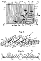
- FIG. 1 is a plan view of one embodiment of the improved screen assembly of the present invention with portions broken away to show the various layers thereof;
- FIG. 2 is a fragmentary enlarged perspective view taken substantially in the direction of arrows 3-3 of FIG. 1;
- FIG. 3 is an end elevational view taken substantially in the direction of arrows 3-3 of FIG. 1;
- FIG. 3A is a fragmentary cross sectional view
taken substantially along
line 3A-3A of FIG. 1 with parts omitted in the interest of clarity; - FIG. 3B is a fragmentary enlarged cross
sectional view taken substantially along
line 3B-3B of FIG. 1; - FIG. 4 is an enlarged fragmentary cross sectional view taken substantially along line 4-4 of FIG. 1;
- FIG. 5 is a cross sectional view taken substantially along line 5-5 of FIG. 4;
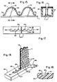
- FIG. 6 is a plan view of a plurality of screen assemblies of FIG. 1 shown in alignment, as they would be on the bed of a vibratory screening machine;
- FIG. 7 is a fragmentary end elevational view taken substantially in the direction of arrows 3-3 of FIG. 1 and showing, in addition, portions of the vibrating screen machine which support the screen asssembly;
- FIG. 8 is a fragmentary perspective view of another embodiment of the present invention;
- FIG. 9 is a fragmentary view of still another embodiment of the present invention;
- FIG. 10 is a fragmentary perspective view of yet another embodiment of the present invention;
- FIG. 11 is a fragmentary perspective view of still another embodiment of the present invention;
- FIG. 12 is a fragmentary plan view of another embodiment of the present invention;
- FIG. 13 is a fragmentary enlarged cross sectional view taken substantially along line 13-13 of FIG. 12;
- FIG. 14 is a fragmentary cross sectional view taken substantially along line 14-14 of FIG. 13;
- FIG. 15 is a fragmentary enlarged view of the end of the screen assembly taken substantially in the direction of arrows 15-15 of FIG. 12;
- FIG. 16 is a fragmentary cross sectional view taken substantially along line 16-16 of FIG. 15;
- FIG. 17 is a fragmentary plan view of a mold which is used in the process of sealing the open ends of the ridges of the screen;
- FIG. 18 is a fragmentary cross sectional view taken substantially along line 18-18 of FIG. 17; and
- FIG. 19 is a fragmentary perspective view of the open ends of the ridges being sealed.
-
- One embodiment of the improved
screen assembly 10 is shown in FIGS. 1-8, and it includes a frame in the form of aperforated metal plate 11, such as steel or any other suitable metal, having a first pair ofopposite edges opposite edges upper surface 16 and alower surface 17.Plate 11 includesapertures 19 which are bordered by elongated metal strip-like portions ormembers 20 which extend betweenedges like portions 21 which extend lengthwise between elongated strip-like portions 20. Theopenings 19 are formed by a punching operation and are quadrangles of approximately 1 inch square with rounded corners but they may be any other desired shape or size. Strip-like portions plate 11 betweenedges edges plate 11 may vary as required to fit different machines. The width of eachopening 19 is a small fraction of the length of the plate betweenedges openings 19 and the width of the plate betweenedges shaped members plate 11 atedges shaped member 23 is bent to the shape shown in FIG. 3B from a single piece of metal and itsends plate 11 and are welded thereto. Channel-shaped member 22 is of the same construction and is welded toplate 11 in the same manner. The foregoing description ofplate 11 is essentially set forth in U.S. Patent No. 4,575,421. As will be apparent hereafter, any suitable plate or any suitable frame which provides the frame portions or members to which a screen can be attached may be utilized. - In accordance with the present invention, the
screen 24 is corrugated in the sense that it is formed in an undulating triangular shape having elongated substantially triangularparallel ridges 25 with downwardly slopingsides 27.Troughs 29 are formed between the downwardly sloping sides for conducting material which is being screened in the direction of arrow 30 (FIGS. 1 and 6) across the width of the screen in substantially parallel rows. This prevents the material being screened from gravitating toward thesides screen assembly 10 is mounted in bowed condition on avibratory screening machine 31, as schematically depicted in FIG. 7. - The
screen 24 includes acoarse support screen 32 having bonded thereto afine screening screen 33.Coarse screen 32 may be anywhere between 4 and 24 mesh, or any other suitable size. Thefine screening screen 33 may be between 50 and 400 mesh or any other suitable size. The coarseness of the support screen and the fineness of the fine screening screen which are used in any application would depend on the material being screened, and whether the screening is being effected dry or wet. Thefine screening screen 33 is bonded to thecoarse support screen 32 at points where their wires intersect by a suitable adhesive such as epoxy. In addition, wherever the apices 34 (FIGS. 4 and 5) cross overelongated frame members 20, they are adhesively bonded thereto by epoxy. Thus, there will be a bond to thereby firmly securescreen 24 toplate 11 so that it can withstand the high G forces to which it is subjected. Thus, for example, there will be bonds at points such as 35 (FIG. 5). However, any other suitable securing arrangement for rigidly securingscreen 24 to plate 11 may be used. - The
screen 24 is formed on a brake to the triangular shape shown afterscreens sides 27 extend at a 45° angle to plate 11 and thus the angle betweensides 27 will be 90°. However, sides 27 can extend at any desired angle relative to each other. Additionally, the undulating shape need not be triangular but it may be sinusoidal or any other suitable cross sectional configuration which will provide elongated substantially parallel ridges with troughs therebetween. Thus, the vertices at the lowermost portions of thetroughs 29 need not be a sharp angle as shown but can be curved. - The supporting
screen 32 need be sufficiently strong to maintain the integrity of the undulating shape to bear the brunt of any rocks and heavy debris to which the screen is subjected. Furthermore, thecoarse support screen 32 need be of a sufficiently close mesh so as to prevent tearing of thescreening screen 33 which lies on top of it. - The
sides plate 11 are formed intotriangles 37 and 37', respectively, which are bent up at a right angle to the main body of the plate, and the edges of thetriangles 37 are sealed, as by adhesive or welding, to the end edges 38 of the undulating ridges at 39 to thereby completely close the ends ofridges 25. This prevents the material from being screened from entering the openings closed bytriangles 37. Any other suitable arrangements can be utilized for blocking the ends of theridges 25. - The
screen assembly 10, in addition to channeling screening material throughtroughs 29, also provides a greater screening surface than a flat screen, such as shown in Patent No. 4,575,421. In this respect, depending on the triangular configuration, the screening area is a multiple of the screening area of the screen shown in the prior patent. In the specific embodiment shown where thesides 27 are at an angle of 45° to the plate, the screen has approximately 1.8 times the screening area of a flat screen. In addition, because thesides 27 are at an angle and because the oscillation of the screen is in a vertical direction, there is less blinding because the particles which are moved up and down hit thescreening screen 33 at an angle rather than perpendicularly, as would be the case with a flat screen. In operation, the particles do not gravitate into the bottoms of thetroughs 29 but they are distributed along thesides 27. It is actually thesides 27 which guide the particles in the direction of thetroughs 29. - In FIG. 6 there is a schematic showing of three
screens 10 in perfect alignment with each other, that is, thetroughs 29 of each of the screens and theridges 24 of each of the screens are in alignment so that the material to be screened which is traveling in the direction ofarrow 30 will pass from one screen to the next without being obstructed by the ends of the screens which are blocked bytriangles 37 and 37'. - The
screen assembly 10 can be mounted in a vibratingscreening machine 31 by means of elongated channel-shapeddrawbars channels bolt assemblies Screen assembly 10 rests on a frame (not fully shown) having a plurality ofelongated members channels screen assembly 10 is bowed slightly so that its center along a line parallel toedges outer edges screen assembly 10 can be mounted in any other manner by any other type of mounting arrangement, depending on the machine in which it is used. In addition, in certain instances, thescreen assembly 10 may be mounted flat or, if a different type of frame is utilized rather than theplate 11, the frame may be mounted in any suitable manner, depending on the machine. - In use, the
screen assembly 10 may be inclined downwardly fromupper edge 15 tolower edge 14 or it may be horizontal, or it may be inclined upwardly fromedge 15 to edge 14. Material is fed onto the screen atedge 15 and it passes towardedge 14 asscreen assembly 10 is vibrated in the conventional manner. In this respect, the vibration is an oscillation in the plane of the direction of arrows 30 (FIGS. 1 and 6), that is it is in the same direction as the flow of the material which is being screened. More specifically, the oscillation is in a forward and rearward direction coupled with an up and down motion, but there is no appreciable sidewise motion. The oscillation is effected under high G forces between about 2G and 9G, depending on the material being screened. It is for this reason, namely, the high G forces that theframe 11 has to be sufficiently strong, and thesupport screen 32 has to be sufficiently strong to support the expanses ofscreening screen 33 bonded thereto, andsupport screen 32 has to be bonded at multiple points along its length to prevent it from being detached from theplate 11 during oscillation. - Another embodiment of the improved screen assembly is shown in FIG. 8.
Screen assembly 10a utilizes ametal frame 50 consisting of a rectangularouter frame 51 consisting of twotubular members 52 and twotubular members 53.Tubular frame members 54 extend lengthwise between and are suitably secured to the twomembers 53 andtubular members 55 extend lengthwise between and are suitably secured totubular members 54. Adjacenttubular members 55 are not aligned with each other, so that screened material will not travel along onemember 55 onto anothermember 55. Ascreen 24 is provided having acoarse screen 32 with afine screen 33 bonded thereto, as described in FIGS. 1-8.Screen 24 is adhesively bonded totubular members 54. Theframe members apertures 56 therebetween through which screened material passes after it has been screened byscreen 24. Suitable channels, such as 22 and 23 (FIGS. 1-8), may be welded to framemembers 53 for mountingscreen assembly 10a on a vibratory screen machine, or any other suitable mounting arrangement can be used. Thescreen assembly 10a is suited for mounting on a vibratory screening machine having a flat bed, considering that thetubular frame 51 is not flexible likeplate 11 of FIGS. 1-8. It is to be noted that triangular plates, such as 37 of FIGS. 1-8, cannot be used to block off the ends of theridges 25 but other blocking arrangements, such as described hereafter with other embodiments, can be used. While theframe 50 has been described above as being fabricated of tubular members, it will be appreciated that under certain circumstances it may be fabricated of solid rods if the weight is not excessive. - Another embodiment 10b is shown in FIG. 9. This embodiment includes a perforated plate which may be identical to plate 11 of FIGS. 1-8 and which has suitable channels, such as 22 and 23, affixed thereto for mounting the screen assembly 10b on a vibratory screening machine. In this embodiment, a coarse screen 32' and a fine screen 33' are bonded, as by epoxy adhesive, to a
perforated plate 57 havingapertures 59 therein.Plate 57 and screens 32' and 33' are bent into an undulating shape having ridges 25' and troughs 29'. The troughs 29' terminate at apices 34'. The undersides of apices 34' are welded or otherwise suitably bonded at spaced locations along their lengths to plate 11 in the same manner described above relative to FIGS. 2-8.Plate 11 may include bent uptriangles 37 for blocking the ends ofridges 25 in the same manner described above relative to FIGS. 2-8. The purpose for utilizing aperforated plate 57 is to lend strength to the screens 32' and 33' against deformation by rocks. In this embodiment, if desired, only one screening screen may be bonded to plate 57 ifplate 57 lends sufficient support to it. In fact in any of the embodiments, a single screen can be bonded to the frame at various points along the lengths of the troughs if the screen is sufficiently strong to withstand the forces which are applied to it, and this would generally apply to screens which have relatively large wire sizes, such as screens which are between about 10 and 50 mesh which will not distort excessively when subjected to the forces produced by the vibratory screening machine. - In FIG. 10 a further modified screen assembly 10c is shown. This assembly may take the form of any of the preceding screens except that it does not have the folded-up triangular ends 37 for blocking the openings to
ridges 25. Instead, bothscreens ridges 25 to form acover 60 by joiningportions seam 63, which may be formed by adhesive or welding or brazing or in any other suitable manner. The lowermost side ofcover 60 is sealed to plate 11 along joint 66. This arrangement for sealing the ends ofridges 25 may be utilized in any of the precedingembodiments - In FIG. 11 a further modified screen assembly 10d is shown which utilizes a triangular
plastic insert 65 to seal the end of ridges, such as 25. The plastic insert can consist of atriangular portion 67 havingflanges 69 and 70, respectively, which are placed in contiguous abutting lapped relationship with the inner end edge surfaces ofplate 11 andridges 25, respectively. Suitable adhesive or sealant, such as epoxy,bonds flanges 69 and 70 in position.Plastic plates 65 may be utilized in any of the preceding embodiments. - In FIGS. 12-19 a preferred embodiment of the present invention is disclosed. This embodiment comprises a screen assembly 10' which includes a frame in the form of a
perforated metal plate 11 which may be identical to plate 11 described above with respect to FIGS. 1-8, and accordingly the same numerals will be applied to this plate, and a description will be omitted at this point in the interest of brevity. It will be understood that the numerals on this plate which are identical to the numerals of the plate of FIGS. 1-8 represent identical elements of structure. - The screen assembly 10' of FIGS. 12-19 differs from the preceding embodiment shown in FIGS. 1-8 in that the
corrugated screen 75 of screen assembly 10' is of an undulating curved shape rather than an undulating triangular shape. In addition, it possesses three layers of screening instead of the two layers shown in FIGS. 1-8. More specifically, thescreen 75 comprises abase screen 77, anintermediate screen 79 and anuppermost screen 80. These screens are formed into an undulating curved shape which includescurved ridges 76 andcurved troughs 78.Screens undersides 82 of thetroughs 78 are bonded to plate 11 by epoxy wherever they crossportions plate 11.Base screen 77 is in the nature of a supporting screen and it may have a mesh size of between about 3 mesh and 8 mesh. Theintermediate screen 79 may have a mesh size of between 30 mesh and 325 mesh. Theuppermost screen 80 is of finer mesh thanintermediate screen 79 and it may have a mesh size of between 40 mesh and 400 mesh. Preferably theintermediate screen 79 should be two U.S. sieve sizes coarser than theuppermost screen 80. - The open ends of the
ridges 76 ofscreen 75 are sealed or blocked bypolyurethane caps 83 which are molded into place. To accomplish this, a screen assembly consisting ofplate 11 withscreen 75 bonded thereto is oriented vertically, and an end of the screen is placed into amold 84. In this mold, thescreen 75 is placed in contiguous abutting complementary relationship withcurved surface 85, and the edge ofplate 11 is placed in abutting relationship withedge 87 of the mold. The end surfaces of thescreen 75 andplate 11 are placed in abutting relationship with theplanar bottom 89 of the mold, and the channel-shaped side edges 12 and 13 ofplate 11 are placed inmating openings 90 of themold 84. Liquid polyurethane is then pumped into the open end of each ridge to the proper depth by inserting thepump 86 through theaperture 19 in theplate 11 which is proximate to the open end of theridge 76 which is to be blocked, and the liquid polyurethane is filled to the proper depth in the mold. This is shown in FIG. 18. The polyurethane penetrates thescreen 75 and also adheres to theplate 11, and after the polyurethane solidifies, acap 83 is firmly bonded to the open end of eachridge 76. Thecaps 83, in addition to serving their blocking function, also rigidize the edges of thescreen 75. - Since
screen 75 is of curved shape, itscrests 81 are rounded, as compared with the pointed crests or apices of the triangular screen of FIGS. 1-8. Also, theapices 82 at the undersides oftroughs 78 are rounded which provides more contact area withplate 11 than is possible with theapices 34 of the triangular screen of FIGS. 1-8. Theundersides 82 oftroughs 78 are bonded to the contacting portions ofplate 11 by means of epoxy, as noted above. Sinceapices 82 have an effective wider tread thanapices 34 of FIGS. 1-8, more secure bonding is obtained wherever the contact exists. Additionally, the rounded crests orapices 81 provide longer life because there are no acute stress areas due to sharp bends. Additionally, the screen according to FIGS. 12-19 provides improved performance because the material which is being screened does not slide sideways as rapidly from the curved crests orapices 81 and because there is a broader base at thebottoms 83 of the curved troughs and thus less clogging. - A screen which has proved satisfactory in operation had the following dimensions: The
plate 11 had the dimensions set forth above relative to FIGS. 1-8. Thebase screen 77 was 4 mesh, theintermediate screen 79 was 180 mesh and theuppermost screen 80 was 200 mesh.Curved screen 75 had a dimension of 1.6 inches between cycles, that is 1.6 inches between adjacent crests and 1.6 inches between the bottom of adjacent troughs. Also, the radii at the bottoms of the troughs was 1/4 inch and the radii at thecrests 81 was 1/2 inch. The height of the ridges fromplate 11 to the tops 81 was one inch. It will be appreciated that the curvature may be of any desired dimension which will provide the proper results. - The use of a triple layer consisting of
screens base screen 77 provides rigidity without significantly blocking the openings in the twoscreens Intermediate screen 79 provides support touppermost screen 80 and it in turn is supported bybase screen 77. - While the preferred way of blocking the open ends of the screen 10' has been described above by the polyurethane caps 83, the ends of
screen 75 can be blocked by any of the structures disclosed above. More specifically, the open ends can be blocked by suitably shaped tabs such as 37 of FIG. 2 bent up fromplate 11. Also, the open ends of the screens can be blocked by the method shown in FIG. 10 or by suitably shaped plastic inserts of the type shown and described above relative to FIG. 11. - The screen assemblies described above can be utilized for dry screening, or can be utilized for wet screening of drilling mud which is a slurry of mud and water, and it can also be utilized for other liquid suspensions, such as kaolin and water. A machine of the type which performs a wet screening operation is disclosed in U.S. Patent No. 4,882,054.
- It can thus be seen that the improved screen assemblies of the present invention are manifestly capable of achieving the above-enumerated objects, and while preferred embodiments of the present invention have been disclosed, it will be appreciated that it is not limited thereto but may be otherwise embodied within the scope of the following claims.
Claims (24)
- A screen assembly for a vibratory screening machine comprising a frame, a plurality of apertures in said frame, spaced frame members on opposite sides of said plurality of apertures, a screen formed in an undulating shape with elongated substantially parallel ridges having downwardly sloping sides, troughs formed between said downwardly sloping sides for conducting material which is being screened, undersides on said troughs, securing means for securing said undersides of said troughs to said spaced frame members on the opposite sides of a plurality of said apertures whereby said elongated substantially parallel ridges are positioned above said frame and in spaced relationship to said frame, and means for securing said frame to a vibratory screening machine.
- A screen assembly as set forth in claim 1 wherein said frame has a length and a width, and wherein said plurality of apertures comprise a plurality of apertures extending in the direction of said length and a plurality of apertures extending in the direction of said width.
- A screen assembly as set forth in claim 1 or claim 2 wherein said screen comprises a coarse supporting screen for placement adjacent said frame, and a fine screening screen bonded to said coarse screen on the opposite side of said coarse screen from said frame.
- A screen assembly as set forth in any one of claims 1 to 3 including a perforated plate formed in the same undulating shape as said screen and located in underlying relationship to said screen and bonded to said frame.
- A screen assembly as set forth in any one of claims 1 to 4 wherein said frame comprises an apertured plate and said frame members comprise strip-like members of said plate, and wherein said securing means secure said undersides of said troughs to said strip-like members.
- A screen assembly as set forth in claim 1 wherein said frame comprises a configuration of rod-like members.
- A screen assembly as set forth in any one of claims 1 to 5 wherein said elongated ridges have end portions, and said screen assembly includes sealing means for sealing said end portions of said elongated ridges against entry of material which is being screened.
- A screen assembly as set forth in claim 7 when dependent on claim 5 wherein said sealing means comprises bent-up portions of said apertured plate.
- A screen assembly as set forth in claim 7 wherein said sealing means comprises extensions of said screen covering said end portions of said ridges.
- A screen assembly as set forth in claim 7 wherein said sealing means comprises inserts installed in said end portions of said ridges.
- A screen assembly as set forth in any one of the preceding claims wherein said elongated ridges are of triangular cross sectional shape.
- A screen assembly as set forth in claim 1 wherein said frame members extend crosswise to said ridges and said troughs, and wherein said undersides of said troughs are secured at spaced locations to said frame members.
- A screen assembly as set forth in claim 12 wherein said securing means comprise bonds between said undersides of said troughs and said frame members.
- A screen assembly as set forth in claim 1 wherein said screen is of undulating curved cross section wherein said ridges have apices which are rounded.
- A screen assembly as set forth in claim 14 wherein the bottoms of said troughs are curved and said undersides of said troughs are curved.
- A screen assembly as set forth in claim 14 or claim 15 wherein said screen comprises a base screen of relatively large mesh, a top screening screen of fine mesh, and an intermediate screening screen of less fine mesh than said top screen, said intermediate screen being located between said base screen and said top screen.
- A screen assembly as set forth in any one of claims 14 to 16 wherein said elongated ridges have end portions, and said screen assembly includes means for sealing said end portions of said elongated ridges against entry of material which is being screened.
- A screen assembly as set forth in claim 1 wherein said elongated ridges have end portions, and said screen assembly includes sealing means for sealing said end portions of said elongated ridges against entry of material which is being screened, said sealing means comprising molded cap members which are molded into place in said ridges.
- A screen assembly as set forth in claim 18 wherein said molded cap members penetrate said screen and adhere to said frame.
- A screen assembly as set forth in claim 18 wherein the bottoms of said troughs are curved and said undersides of said troughs are curved.
- A screen assembly as set forth in claim 20 wherein said screen comprises a base screen of relatively large mesh, a top screening screen of fine mesh, and an intermediate screening screen of less fine mesh than said top screen, said intermediate screen being located between said base screen and said top screen.
- A screen assembly as set forth in any one of claims 14 to 21 wherein said frame comprises an apertured plate and said frame members comprise strip-like members of said plate, and wherein said securing means secure said undersides of said troughs to said strip-like members.
- A screen assembly as set forth in claim 22 wherein said means for securing said frame to a vibratory screening machine comprise channel-shaped members at the edges of said plate.
- A plurality of screen assemblies according to any one of the preceding claims for attachment to the bed of a vibratory screening machine, wherein the ridges and the troughs of each of said screen assemblies are aligned with each other.
Applications Claiming Priority (5)
| Application Number | Priority Date | Filing Date | Title |
|---|---|---|---|
| US4122 | 1979-01-17 | ||
| US412293A | 1993-01-13 | 1993-01-13 | |
| US08/062,464 US5417858A (en) | 1993-01-13 | 1993-05-14 | Screen assembly for vibrating screening machine |
| PCT/US1994/000243 WO1994015724A1 (en) | 1993-01-13 | 1994-01-07 | Screen assembly for vibrating screening machine |
| US62464 | 1998-04-17 |
Publications (3)
| Publication Number | Publication Date |
|---|---|
| EP0680386A1 EP0680386A1 (en) | 1995-11-08 |
| EP0680386A4 EP0680386A4 (en) | 1996-01-31 |
| EP0680386B1 true EP0680386B1 (en) | 1999-10-27 |
Family
ID=26672644
Family Applications (1)
| Application Number | Title | Priority Date | Filing Date |
|---|---|---|---|
| EP94906552A Expired - Lifetime EP0680386B1 (en) | 1993-01-13 | 1994-01-07 | Screen assembly for vibrating screening machine |
Country Status (8)
| Country | Link |
|---|---|
| US (4) | US5417858A (en) |
| EP (1) | EP0680386B1 (en) |
| AU (1) | AU693086B2 (en) |
| CA (1) | CA2152610C (en) |
| DE (1) | DE69421381T2 (en) |
| DK (1) | DK0680386T3 (en) |
| ES (1) | ES2137356T3 (en) |
| WO (1) | WO1994015724A1 (en) |
Cited By (1)
| Publication number | Priority date | Publication date | Assignee | Title |
|---|---|---|---|---|
| WO2006130062A1 (en) | 2005-05-31 | 2006-12-07 | Sandvik Intellectual Property Ab | Screening arrangement |
Families Citing this family (114)
| Publication number | Priority date | Publication date | Assignee | Title |
|---|---|---|---|---|
| CH678281A5 (en) * | 1988-10-14 | 1991-08-30 | Werner Nill | |
| US6000556A (en) * | 1993-01-13 | 1999-12-14 | Derrick Manufacturing Corporation | Screen assembly for vibratory screening machine |
| US5958236A (en) * | 1993-01-13 | 1999-09-28 | Derrick Manufacturing Corporation | Undulating screen for vibratory screening machine and method of fabrication thereof |
| US6267247B1 (en) | 1993-04-30 | 2001-07-31 | Tuboscope I/P, Inc. | Vibratory separator screen |
| US6565698B1 (en) | 1993-04-30 | 2003-05-20 | Varco I/P, Inc. | Method for making vibratory separator screens |
| US6371301B1 (en) | 2000-11-17 | 2002-04-16 | Varco I/P, Inc. | Screen basket for shale shakers |
| US6607080B2 (en) * | 1993-04-30 | 2003-08-19 | Varco I/P, Inc. | Screen assembly for vibratory separators |
| US6581781B1 (en) | 1993-04-30 | 2003-06-24 | Tuboscope I/P, Inc. | Vibrator separator screens |
| US6443310B1 (en) | 1993-04-30 | 2002-09-03 | Varco I/P, Inc. | Seal screen structure |
| US6454099B1 (en) | 1993-04-30 | 2002-09-24 | Varco I/P, Inc | Vibrator separator screens |
| US6401934B1 (en) | 1993-04-30 | 2002-06-11 | Tuboscope I/P, Inc. | Ramped screen & vibratory separator system |
| USD425531S (en) * | 1999-03-29 | 2000-05-23 | Tuboscope I/P, Inc. | Screen |
| US5971159A (en) | 1993-04-30 | 1999-10-26 | Tuboscope I/P, Inc. | Screen assembly for a vibratory separator |
| US6290068B1 (en) * | 1993-04-30 | 2001-09-18 | Tuboscope I/P, Inc. | Shaker screens and methods of use |
| US6269953B1 (en) | 1993-04-30 | 2001-08-07 | Tuboscope I/P, Inc. | Vibratory separator screen assemblies |
| US6722504B2 (en) | 1993-04-30 | 2004-04-20 | Varco I/P, Inc. | Vibratory separators and screens |
| US6152307A (en) * | 1993-04-30 | 2000-11-28 | Tuboscope I/P, Inc. | Vibratory separator screens |
| US6283302B1 (en) * | 1993-08-12 | 2001-09-04 | Tuboscope I/P, Inc. | Unibody screen structure |
| US6186337B1 (en) * | 1998-10-30 | 2001-02-13 | Tuboscope I/P, Inc. | Dual screen element having upper scalping screen adhered to crests of corrugated lower screen |
| US6325216B1 (en) | 1993-04-30 | 2001-12-04 | Tuboscope I/P, Inc. | Screen apparatus for vibratory separator |
| US6371302B1 (en) | 1993-04-30 | 2002-04-16 | Tuboscope I/P, Inc. | Vibratory separator screens |
| US5598930A (en) * | 1995-07-20 | 1997-02-04 | Advanced Wirecloth, Inc. | Shale shaker screen |
| US6629610B1 (en) | 1993-04-30 | 2003-10-07 | Tuboscope I/P, Inc. | Screen with ramps for vibratory separator system |
| US6450345B1 (en) | 1993-04-30 | 2002-09-17 | Varco I/P, Inc. | Glue pattern screens and methods of production |
| US6029824A (en) * | 1994-03-30 | 2000-02-29 | Tuboscope I/P, Inc. | Screen for vibrating separator |
| US5551575A (en) * | 1994-07-29 | 1996-09-03 | Environmental Procedures, Inc. | Shale shaker screens |
| US5636749A (en) * | 1995-05-18 | 1997-06-10 | Derrick Manufacturing Corporation | Undulating screen for vibratory screening machine |
| US5814218A (en) * | 1996-01-16 | 1998-09-29 | Cagle; William S. | Distorted rectangular filter cloth screen for vibrating screening machine |
| US5690826A (en) * | 1996-05-10 | 1997-11-25 | Cravello; William Myron | Shaker screen assembly |
| US6000554A (en) * | 1996-05-13 | 1999-12-14 | Comcorp, Inc. | Reciprocating screening conveyor |
| US5921399A (en) * | 1996-06-07 | 1999-07-13 | Derrick Corporation | Gumbo separator |
| US5904254A (en) * | 1996-06-20 | 1999-05-18 | Tinsley, Inc. | Vibratory particle separating apparatus |
| US5744036A (en) * | 1997-02-03 | 1998-04-28 | Aaf International | Pleated filter arrangement |
| JP2001519712A (en) * | 1997-03-18 | 2001-10-23 | ザ・ペン・ステイト・リサーチ・ファウンデイション | Recovery of waste egg shell components |
| US7007806B2 (en) * | 1997-03-18 | 2006-03-07 | The Penn State Research Foundation | Method and apparatus for separating a protein membrane and shell material in waste egg shells |
| US5944197A (en) * | 1997-04-24 | 1999-08-31 | Southwestern Wire Cloth, Inc. | Rectangular opening woven screen mesh for filtering solid particles |
| US5967336A (en) * | 1997-09-02 | 1999-10-19 | Southwestern Wire Cloth, Inc. | Vibrating screen assembly with improved frame |
| US6179128B1 (en) | 1998-10-02 | 2001-01-30 | Tuboscope I/P, Inc. | Tension clamp and screen system |
| US6932883B2 (en) * | 1998-10-30 | 2005-08-23 | Varco I/P, Inc. | Screens for vibratory separators |
| US6736270B2 (en) | 1998-10-30 | 2004-05-18 | Varco I/P, Inc. | Glued screens for shale shakers |
| US20050000865A1 (en) * | 1998-10-30 | 2005-01-06 | Schulte David L. | Screen assemblies and vibratory separators |
| US6662952B2 (en) | 2002-01-16 | 2003-12-16 | Varco I/P, Inc. | Shale shakers and screens for them |
| US20040251175A1 (en) * | 1998-10-30 | 2004-12-16 | Adams Thomas C. | Apparatuses and methods for making glued screen assemblies |
| US20030042179A1 (en) * | 1998-10-30 | 2003-03-06 | Adams Thomas C. | Vibratory separator screens |
| US6769550B2 (en) | 2002-01-16 | 2004-08-03 | Varco I/P, Inc. | Screen assemblies for shale shakers |
| US6669985B2 (en) | 1998-10-30 | 2003-12-30 | Varco I/P, Inc. | Methods for making glued shale shaker screens |
| US6053331A (en) * | 1998-11-17 | 2000-04-25 | Cravello; William M. | Non-tensioned shaker filter |
| US20050035033A1 (en) * | 1999-03-25 | 2005-02-17 | Adams Thomas C. | Methods for sealing screen assemblies on vibratory separators |
| DE19927933B4 (en) * | 1999-06-18 | 2008-07-03 | Gebr. Schumacher Gerätebaugesellschaft mbH | Screen for a threshing machine, in particular for a combine harvester for harvesting grain crops |
| WO2001000332A1 (en) | 1999-06-24 | 2001-01-04 | Varco I/P Inc. | A screen, a panel for a screen, a shale shaker and a method of screening |
| DE19937338A1 (en) * | 1999-08-11 | 2001-02-15 | Steinbeck Job Jorik | Sieving device, method for producing a sieve and sieve for a sieving device |
| US6601709B2 (en) | 1999-09-03 | 2003-08-05 | Tuboscope I/P, Inc. | Screen support and screens for shale shakers |
| EP1212130A1 (en) * | 1999-09-16 | 2002-06-12 | Varco I/P, Inc. | A screen for use in a shale shaker and method for using same |
| US6202856B1 (en) * | 1999-09-22 | 2001-03-20 | Emerson Electric Co. | Vibratory screening system and screen therefor |
| US6220449B1 (en) | 1999-10-01 | 2001-04-24 | Tuboscope I/P, Inc. | Flat top cloth support screen |
| US6510947B1 (en) * | 1999-11-03 | 2003-01-28 | Varco I/P, Inc. | Screens for vibratory separators |
| US20040007508A1 (en) * | 1999-12-04 | 2004-01-15 | Schulte David L. | Screen assembly for vibratory separator |
| US6491168B1 (en) | 2000-04-23 | 2002-12-10 | J + L Fiber Services, Inc. | Pulp screen basket |
| US6431368B1 (en) | 2000-07-05 | 2002-08-13 | Emerson Electric Co. | Vibratory screen |
| US7198156B2 (en) * | 2000-11-17 | 2007-04-03 | Varco I/P, Inc. | Dam basket for vibratory separators |
| US7216767B2 (en) * | 2000-11-17 | 2007-05-15 | Varco I/P, Inc. | Screen basket and shale shakers |
| WO2002083263A1 (en) * | 2001-04-16 | 2002-10-24 | J & L Fiber Services, Inc. | Screen cylinder and method |
| US20050224398A1 (en) * | 2001-10-19 | 2005-10-13 | Largent David W | Vibratory separators and sealing screens |
| US20050103689A1 (en) * | 2001-10-19 | 2005-05-19 | Schulte David L.Jr. | Sealing screen assemblies and vibratory separators |
| US6955262B2 (en) * | 2003-05-02 | 2005-10-18 | Varco, I/P Inc. | Removable seal apparatus for vibratory separator |
| US20050067327A1 (en) * | 2002-01-16 | 2005-03-31 | Adams Thomas C. | Screen assemblies for shale shakers |
| US6790137B2 (en) * | 2002-01-25 | 2004-09-14 | Marvin James Gorden | High capacity air jet chaffer |
| US7186347B2 (en) * | 2002-04-11 | 2007-03-06 | General Kinematics Corporation | Vibratory apparatus for separating liquid from liquid laden solid material |
| US20050242003A1 (en) | 2004-04-29 | 2005-11-03 | Eric Scott | Automatic vibratory separator |
| US20030222032A1 (en) * | 2002-05-29 | 2003-12-04 | Rudiger Tueshaus | Filtering screen construction and methods |
| US6726029B2 (en) | 2002-06-12 | 2004-04-27 | Varco I/P, Inc. | Separator screen with solids conveying end area |
| ATE359853T1 (en) * | 2002-07-08 | 2007-05-15 | Filtrox Ag | PRECAST FILTER CANDLE, PRECAST FILTER AND USE OF A FILTER CANDLE |
| GB2394196A (en) | 2002-10-17 | 2004-04-21 | Varco Int | Screen assembly for a shale shaker |
| US8312995B2 (en) | 2002-11-06 | 2012-11-20 | National Oilwell Varco, L.P. | Magnetic vibratory screen clamping |
| US7682996B2 (en) * | 2002-11-21 | 2010-03-23 | M-I L.L.C. | Vibratory screen |
| US7264125B2 (en) * | 2003-04-23 | 2007-09-04 | Derrick Corporation | Undulating molded plastic vibratory screen |
| US7094297B2 (en) * | 2003-07-25 | 2006-08-22 | Yanco I/P, Inc. | Methods for making screen assemblies |
| DE10352321B3 (en) * | 2003-11-06 | 2005-04-21 | Gustav Schumacher | Sieve for use in harvesting or threshing machine has symmetrical arrangement of grooves running parallel to centerline with openings for grain in vertical walls |
| US20060037891A1 (en) * | 2004-08-20 | 2006-02-23 | Lilie Glenn T | Screen assemblies utilizing screen elements retained in perforated troughs |
| US20050252075A1 (en) * | 2004-05-11 | 2005-11-17 | Blue Rhino Global Sourcing, Llc | Wave shaped screen for insect trap |
| US7757864B2 (en) * | 2004-06-15 | 2010-07-20 | M-I L.L.C. | Screen assembly designed to conform to the radius of vibrating shakers with crowned decks |
| CA2511691A1 (en) * | 2004-07-08 | 2006-01-08 | E.A.I. Technologies | Mobile filtration system and method |
| US7063574B2 (en) * | 2004-10-13 | 2006-06-20 | Power Logic Holdings Ag | Installation coupler |
| US8312996B2 (en) * | 2005-01-21 | 2012-11-20 | Derrick Corporation | Vibratory material screen with seal |
| AU2005202795B2 (en) * | 2005-06-27 | 2007-05-17 | Symphony Wire Pty Ltd | Retention device for filter screen |
| US20070125687A1 (en) * | 2005-12-01 | 2007-06-07 | Kutryk Edward A | Screen assembly for a vibratory separator |
| SE529115E (en) * | 2005-12-14 | 2014-09-17 | Sandvik Intellectual Property | Viewing device |
| US20070289273A1 (en) * | 2006-06-16 | 2007-12-20 | Boyd Kevin E | Air filter with pleat lock |
| US7891497B2 (en) * | 2006-09-29 | 2011-02-22 | M-I L.L.C. | Peripheral sealing system for pre-tensioned screens |
| US20080083566A1 (en) | 2006-10-04 | 2008-04-10 | George Alexander Burnett | Reclamation of components of wellbore cuttings material |
| CA2681366C (en) | 2007-03-21 | 2012-05-08 | Derrick Corporation | Method and apparatuses for pre-screening |
| SE531170C2 (en) * | 2007-05-16 | 2009-01-13 | Metso Minerals Wear Prot Ab | Spiral module for a drum sight |
| US7980392B2 (en) | 2007-08-31 | 2011-07-19 | Varco I/P | Shale shaker screens with aligned wires |
| US8394391B2 (en) * | 2007-08-31 | 2013-03-12 | University Of Utah Research Foundation | Drug delivery vehicle that mimics viral properties |
| US8622220B2 (en) | 2007-08-31 | 2014-01-07 | Varco I/P | Vibratory separators and screens |
| US8070960B2 (en) * | 2007-10-04 | 2011-12-06 | Conwell Michael K | Method of dewatering solids laden liquids utilizing a reusable filter element |
| US9149743B2 (en) | 2007-10-04 | 2015-10-06 | Michael K. Conwell | Apparatus for dewatering solids-laden liquids |
| US20090179134A1 (en) * | 2008-01-10 | 2009-07-16 | General Kinematics Corporation | Modular deck assembly for a vibratory apparatus |
| US8556083B2 (en) | 2008-10-10 | 2013-10-15 | National Oilwell Varco L.P. | Shale shakers with selective series/parallel flow path conversion |
| US9744564B2 (en) | 2012-06-11 | 2017-08-29 | M-I L.L.C. | Vibratory separator screen |
| US9643111B2 (en) | 2013-03-08 | 2017-05-09 | National Oilwell Varco, L.P. | Vector maximizing screen |
| CA2910273C (en) * | 2013-04-30 | 2018-05-29 | M-I Drilling Fluids Uk Ltd. | Screen having frame members with angled surface(s) |
| US10118842B2 (en) * | 2015-07-09 | 2018-11-06 | Imagine Tf, Llc | Deionizing fluid filter devices and methods of use |
| GB2557546A (en) | 2015-09-14 | 2018-06-20 | M I Drilling Fluids Uk Ltd | Clip & seal assembly |
| GB2562431B (en) * | 2016-04-04 | 2021-11-24 | Halliburton Energy Services Inc | Vibratory screening panel |
| CN106140598B (en) * | 2016-08-24 | 2018-06-08 | 何建慧 | A kind of yellow mud screening machine |
| US11185801B2 (en) | 2016-10-14 | 2021-11-30 | Derrick Corporation | Apparatuses, methods, and systems for vibratory screening |
| JOP20190082A1 (en) | 2016-10-14 | 2019-04-14 | Dirrick Corp | Apparatus , methods , and systems for vibratory screening |
| USD890236S1 (en) | 2019-02-07 | 2020-07-14 | Derrick Corporation | Vibratory screening machine |
| US11052427B2 (en) | 2016-10-14 | 2021-07-06 | Derrick Corporation | Apparatuses, methods, and systems for vibratory screening |
| EA202091698A3 (en) * | 2017-04-21 | 2021-01-29 | Деррик Корпорейшн | VIBRATING SCREEN, SIEVE DECK UNIT AND METHOD FOR SCREENING MATERIAL |
| WO2020069553A1 (en) * | 2018-10-02 | 2020-04-09 | Bruce Neumann | Screen shield assembly |
| CA3130757A1 (en) | 2019-02-20 | 2020-08-27 | Dsi Tunneling Llc | Underground support system and method |
| WO2022140568A1 (en) * | 2020-12-23 | 2022-06-30 | Continental Wire Cloth, LLC | Shaker screen assembly with undulation sealing tabs |
Family Cites Families (98)
| Publication number | Priority date | Publication date | Assignee | Title |
|---|---|---|---|---|
| US40242A (en) * | 1863-10-13 | Improvement in grain-sieves | ||
| US275340A (en) * | 1883-04-03 | kimball | ||
| US526562A (en) * | 1894-09-25 | Coal-screen | ||
| US246144A (en) * | 1881-08-23 | Fanning-mill | ||
| BE505776A (en) * | ||||
| CA599661A (en) * | 1960-06-14 | H. Eaton-Williams Raymond | Fluid filters formed of fabrics containing thermoplastic yarns | |
| US500302A (en) * | 1893-06-27 | Slate-picker | ||
| US560858A (en) * | 1896-05-26 | missroon | ||
| US607598A (en) * | 1898-07-19 | Grain-separating screen for th resh ing-ivlach in es | ||
| US691045A (en) * | 1900-11-09 | 1902-01-14 | William W Climenson | Machine for separating cockle from wheat. |
| US800693A (en) * | 1904-12-28 | 1905-10-03 | John A Traylor | Shaking-screen. |
| US964144A (en) * | 1907-08-16 | 1910-07-12 | Irenee Alexis Chavanne | Centrifugal bolting-machine. |
| US964897A (en) * | 1908-04-04 | 1910-07-19 | Noah Bryant | Save-all for paper-making machines. |
| US966578A (en) * | 1908-04-20 | 1910-08-09 | Sherman P Murphy | Screen for threshing-machines. |
| US984866A (en) * | 1909-05-06 | 1911-02-21 | Earl H Tate | Aero ore-concentrator and placer-machine. |
| US1132667A (en) * | 1910-06-16 | 1915-03-23 | Louis Milliot | Florist's dirt-sieve. |
| US1009069A (en) * | 1911-04-26 | 1911-11-21 | Charles Hunnicutt | Seed-corn grader. |
| US1098979A (en) * | 1912-01-22 | 1914-06-02 | Karl Schuchard | Jigging-machine. |
| US1131667A (en) * | 1914-10-24 | 1915-03-16 | Emil Bommer | Spring-hinge. |
| US1269085A (en) * | 1917-02-26 | 1918-06-11 | Samuel A Jeske | Grain-separator. |
| US1423021A (en) * | 1919-09-22 | 1922-07-18 | Tyler Co W S | Screening apparatus |
| US1462804A (en) * | 1922-04-18 | 1923-07-24 | Evans Edward James | Sieve |
| US1561632A (en) * | 1924-02-27 | 1925-11-17 | Herbert S Woodward | Perforated indented screen |
| US1947307A (en) * | 1931-01-21 | 1934-02-13 | Rafton Engineering Corp | Means for supporting wire cloth |
| US1997740A (en) * | 1931-12-24 | 1935-04-16 | Tyler Co W S | Plural cloth screening apparatus |
| US1997713A (en) * | 1932-08-08 | 1935-04-16 | Tyler Co W S | Screen and method of making same |
| US2038071A (en) * | 1932-11-09 | 1936-04-21 | Patent Finance Corp | Fluid treating device |
| US2082513A (en) * | 1934-07-26 | 1937-06-01 | Western States Machine Co | Filter sieve and art of making the same |
| GB457924A (en) * | 1935-03-09 | 1936-12-09 | Tyler Co W S | Improvements in screening or sifting apparatus |
| US2089548A (en) * | 1935-03-12 | 1937-08-10 | Colorado Fuel & Iron Corp | Means of filtration |
| GB519680A (en) * | 1938-09-22 | 1940-04-03 | James Walker | Improvements in or relating to strainer plates and drums |
| US2274700A (en) * | 1939-02-14 | 1942-03-03 | Tyler Co W S | Screening apparatus |
| US2315055A (en) * | 1940-07-19 | 1943-03-30 | Richard D Heller | Screen cloth |
| US2462878A (en) * | 1942-11-23 | 1949-03-01 | Mining Process & Patent Co | Vibrating screen with vacuum control therefor |
| US2406051A (en) * | 1943-06-26 | 1946-08-20 | Paul Porzelt | Apparatus for producing corrugated structures |
| US2648441A (en) * | 1948-01-17 | 1953-08-11 | Productive Equipment Corp | Vibrating equipment |
| US2723032A (en) * | 1950-12-18 | 1955-11-08 | Mining Process & Patent Co | Vibrating screens |
| GB743902A (en) * | 1951-04-12 | 1956-01-25 | Siteg Siebtech Gmbh | Vibrating screens |
| US2726184A (en) * | 1952-11-01 | 1955-12-06 | Purolator Products Inc | Method of providing seals for filters |
| GB823648A (en) * | 1956-09-27 | 1959-11-18 | Air Maze Corp | Filters for fluids |
| US2957235A (en) * | 1957-03-12 | 1960-10-25 | Purolator Products Inc | Method of joining powder metal parts |
| US2980208A (en) * | 1957-05-21 | 1961-04-18 | Delbag Luftfilter Gmbh | Filter element for extremely fine dust |
| US3057481A (en) * | 1958-06-12 | 1962-10-09 | Pall Corp | Corrugated filter and method of forming the same |
| US2929464A (en) * | 1959-05-18 | 1960-03-22 | Vernco Corp | Flat knit filter media |
| US3165473A (en) * | 1960-10-24 | 1965-01-12 | Pall Corp | Corrugated filter unit |
| US3306794A (en) * | 1963-02-12 | 1967-02-28 | Wix Corp | Method of making a filter element |
| US3255885A (en) * | 1963-02-27 | 1966-06-14 | Nordberg Manufacturing Co | Vibrating screen |
| DE1206372B (en) * | 1964-09-26 | 1965-12-09 | Albert Wehner | Screen grate |
| US3374886A (en) * | 1966-05-02 | 1968-03-26 | Arthur S. Lightsey | Grain separator chaffer assembly |
| US3465413A (en) * | 1966-10-25 | 1969-09-09 | Universal Filters Inc | Method of manufacturing pleated filters |
| US3567510A (en) * | 1967-12-20 | 1971-03-02 | Canadian Cane Equip | Method and apparatus for separating components of sugarcane |
| DE1758860A1 (en) * | 1968-08-22 | 1971-06-03 | Stahlgruber Gruber & Co Otto | Elastic sieve bottom |
| US3679057A (en) * | 1970-09-11 | 1972-07-25 | Damasco Rodolfo Adelto Perez | Screen filter pack and method for making same |
| US3747772A (en) * | 1971-05-21 | 1973-07-24 | Parker Hannifin Corp | Filter |
| US3853529A (en) * | 1971-06-09 | 1974-12-10 | Farr Co | Pleated air filter cartridge |
| US4064051A (en) * | 1972-06-02 | 1977-12-20 | Hein, Lehmann Akt. | Elastic transporting, sieving or filtering base with swinging drive |
| US3970549A (en) * | 1973-06-18 | 1976-07-20 | Linatex Corporation Of America | Screen assembly and dewatering technique |
| US4033865A (en) * | 1974-12-09 | 1977-07-05 | Derrick Manufacturing Corporation | Non-clogging screen apparatus |
| US4022596A (en) * | 1975-08-27 | 1977-05-10 | Pedersen George C | Porous packing and separator medium |
| GB1512958A (en) * | 1975-10-06 | 1978-06-01 | Crosland Filters Ltd | Filter |
| US4019987A (en) * | 1976-01-14 | 1977-04-26 | Leonard L | Extended area filters |
| US4075106A (en) * | 1976-05-07 | 1978-02-21 | Masahiko Yamazaki | Filtering device |
| JPS6012878B2 (en) * | 1978-08-24 | 1985-04-03 | 株式会社東芝 | Control method of induction motor |
| US4512892A (en) * | 1980-02-14 | 1985-04-23 | Millipore Corporation | Method and structure for sealing tubular filter elments |
| US4380494A (en) * | 1980-04-14 | 1983-04-19 | Litton Systems, Inc. | Vibrating screen with self-supporting screen cloth |
| US4464263A (en) * | 1980-09-02 | 1984-08-07 | Fram Corporation | Pleated filter element and integral shield and method for making same |
| US4517090A (en) * | 1982-03-30 | 1985-05-14 | Baxter Travenol Laboratories, Inc. | Low volume, large area filters for IV or blood filtration |
| EP0100132A3 (en) * | 1982-07-24 | 1984-08-22 | Derek Parnaby Cyclones International Limited | Dewatering and compacting screen |
| US4526121A (en) * | 1982-08-30 | 1985-07-02 | Hitachi Shipbuilding & Engineering Co., Ltd. | Ship for treating coal slurry |
| JPS59142818A (en) * | 1983-02-01 | 1984-08-16 | Seibu Giken:Kk | Manufacture of filter element |
| US4594162A (en) * | 1984-02-13 | 1986-06-10 | American Filtrona Corporation | Pleated filter and method and apparatus for fabricating same |
| US4575421A (en) * | 1984-03-08 | 1986-03-11 | Derrick Manufacturing Corporation | Non-clogging wear-reducing screen assembly for vibrating screening machine |
| US4582597A (en) * | 1984-04-04 | 1986-04-15 | Sweco, Incorporated | Vibratory screen separator |
| US4617122A (en) * | 1984-08-01 | 1986-10-14 | Donaldson Company, Inc. | Crimp seal pleated filter assembly |
| GB2162768B (en) * | 1984-08-06 | 1989-01-11 | Tilghman Wheelabrator Ltd | Filtering apparatus |
| US4647373A (en) * | 1984-08-30 | 1987-03-03 | Donaldson Company, Inc. | Multi-layered filter apparatus |
| JPH0629116Y2 (en) * | 1985-04-12 | 1994-08-10 | 株式会社東海理化電機製作所 | Lamp burnout detection device |
| US4696751A (en) * | 1986-08-04 | 1987-09-29 | Dresser Industries, Inc. | Vibratory screening apparatus and method for removing suspended solids from liquid |
| US4701197A (en) * | 1986-10-07 | 1987-10-20 | Allied Corp. | Molded panel filter |
| US4758333A (en) * | 1987-03-23 | 1988-07-19 | General Electric Company | Sieve |
| US4820407A (en) * | 1987-04-24 | 1989-04-11 | Cpi Sales, Inc. | Solids screens |
| US4940500A (en) * | 1987-08-31 | 1990-07-10 | Tsuchiya Mfg. Co., Ltd. | Filter medium forming system and process |
| JPH01203010A (en) * | 1988-02-08 | 1989-08-15 | Goyo Kogyo Kk | Molding method for filter unit |
| WO1989010781A1 (en) * | 1988-05-04 | 1989-11-16 | Knecht Filterwerke Gmbh | Strips of filter material with moulded corrugations and filter bodies made of this material |
| DE3818972C2 (en) * | 1988-06-03 | 1998-04-16 | Hartwig Straub | Filter insert for a solid filter |
| US4954249A (en) * | 1988-06-10 | 1990-09-04 | Beloit Corporation | Wave screen plate |
| US5084178A (en) * | 1988-06-15 | 1992-01-28 | Pall Corporation | Corrugated filter arrangement with support layer and flow channels |
| US4832834A (en) * | 1988-07-11 | 1989-05-23 | Baird Jr Howard R | Elastomer sieve screen |
| US4882054A (en) * | 1988-08-22 | 1989-11-21 | Derrick Manufacturing Corporation | Vibratory screening machine with tiltable screen frame and adjustable discharge weir |
| US5139154A (en) * | 1989-12-27 | 1992-08-18 | Beloit Corporation | Wear screen plate and method of manufacture thereof |
| DE4002078C1 (en) * | 1990-01-25 | 1991-05-02 | Fa. Carl Freudenberg, 6940 Weinheim, De | |
| FR2661196B1 (en) * | 1990-04-18 | 1992-07-17 | Lamort Em | SCREEN FOR PURIFIER AND PULP CLASSIFIER. |
| US5221008A (en) * | 1990-05-11 | 1993-06-22 | Derrick Manufacturing Corporation | Vibratory screening machine and non-clogging wear-reducing screen assembly therefor |
| TW199108B (en) * | 1991-11-11 | 1993-02-01 | British United Shoe Machinery | |
| US5312508A (en) * | 1992-10-16 | 1994-05-17 | John Chisholm | Attaching crimped wire mesh to an object requiring heat transfer |
| US5490598A (en) * | 1994-03-30 | 1996-02-13 | Drexel Oilfield Services, Inc. | Screen for vibrating separator |
| US5598930A (en) * | 1995-07-20 | 1997-02-04 | Advanced Wirecloth, Inc. | Shale shaker screen |
| US5551575A (en) * | 1994-07-29 | 1996-09-03 | Environmental Procedures, Inc. | Shale shaker screens |
-
1993
- 1993-05-14 US US08/062,464 patent/US5417858A/en not_active Expired - Lifetime
-
1994
- 1994-01-07 DK DK94906552T patent/DK0680386T3/en active
- 1994-01-07 ES ES94906552T patent/ES2137356T3/en not_active Expired - Lifetime
- 1994-01-07 DE DE69421381T patent/DE69421381T2/en not_active Expired - Lifetime
- 1994-01-07 AU AU60231/94A patent/AU693086B2/en not_active Expired
- 1994-01-07 EP EP94906552A patent/EP0680386B1/en not_active Expired - Lifetime
- 1994-01-07 WO PCT/US1994/000243 patent/WO1994015724A1/en active IP Right Grant
- 1994-01-07 CA CA002152610A patent/CA2152610C/en not_active Expired - Lifetime
-
1995
- 1995-05-17 US US08/443,381 patent/US5720881A/en not_active Expired - Lifetime
-
1996
- 1996-12-20 US US08/770,921 patent/US5868929A/en not_active Expired - Lifetime
-
1997
- 1997-11-25 US US08/978,089 patent/US5944993A/en not_active Expired - Lifetime
Cited By (2)
| Publication number | Priority date | Publication date | Assignee | Title |
|---|---|---|---|---|
| WO2006130062A1 (en) | 2005-05-31 | 2006-12-07 | Sandvik Intellectual Property Ab | Screening arrangement |
| US8066126B2 (en) | 2005-05-31 | 2011-11-29 | Sandvik Intellectual Property Ab | Screening arrangement |
Also Published As
| Publication number | Publication date |
|---|---|
| DE69421381D1 (en) | 1999-12-02 |
| CA2152610C (en) | 1999-06-29 |
| WO1994015724A1 (en) | 1994-07-21 |
| EP0680386A4 (en) | 1996-01-31 |
| DK0680386T3 (en) | 2000-01-24 |
| US5417858A (en) | 1995-05-23 |
| US5944993A (en) | 1999-08-31 |
| US5720881A (en) | 1998-02-24 |
| CA2152610A1 (en) | 1994-07-21 |
| AU693086B2 (en) | 1998-06-25 |
| AU6023194A (en) | 1994-08-15 |
| DE69421381T2 (en) | 2000-04-06 |
| ES2137356T3 (en) | 1999-12-16 |
| EP0680386A1 (en) | 1995-11-08 |
| US5868929A (en) | 1999-02-09 |
Similar Documents
| Publication | Publication Date | Title |
|---|---|---|
| EP0680386B1 (en) | Screen assembly for vibrating screening machine | |
| US5971159A (en) | Screen assembly for a vibratory separator | |
| US6325216B1 (en) | Screen apparatus for vibratory separator | |
| US5385669A (en) | Mining screen device and grid structure therefor | |
| US5221008A (en) | Vibratory screening machine and non-clogging wear-reducing screen assembly therefor | |
| EP1833592B1 (en) | Improvements in and relating to sifting screens | |
| US6454099B1 (en) | Vibrator separator screens | |
| US4033865A (en) | Non-clogging screen apparatus | |
| US6601709B2 (en) | Screen support and screens for shale shakers | |
| EP1333904B1 (en) | A screen for a shale shaker | |
| US6241098B1 (en) | Drilling fluid treatment operations and apparatuses | |
| US20050224398A1 (en) | Vibratory separators and sealing screens | |
| US20050103689A1 (en) | Sealing screen assemblies and vibratory separators | |
| US6029824A (en) | Screen for vibrating separator | |
| US20050000865A1 (en) | Screen assemblies and vibratory separators | |
| AU714591B2 (en) | Screen assembly for vibrating screening machine | |
| US20200230653A1 (en) | Screening Material and Screen Assembly | |
| EP1270058B1 (en) | A screen for use in a shale shaker and method for using same | |
| AU712862B2 (en) | Fine ore screening panel | |
| CA1081658A (en) | Two-ply crowned-and-tensioned anti-clogging screen system |
Legal Events
| Date | Code | Title | Description |
|---|---|---|---|
| PUAI | Public reference made under article 153(3) epc to a published international application that has entered the european phase |
Free format text: ORIGINAL CODE: 0009012 |
|
| 17P | Request for examination filed |
Effective date: 19950704 |
|
| AK | Designated contracting states |
Kind code of ref document: A1 Designated state(s): BE DE DK ES FR GB IT NL |
|
| A4 | Supplementary search report drawn up and despatched | ||
| AK | Designated contracting states |
Kind code of ref document: A4 Designated state(s): BE DE DK ES FR GB IT NL |
|
| 17Q | First examination report despatched |
Effective date: 19980414 |
|
| GRAG | Despatch of communication of intention to grant |
Free format text: ORIGINAL CODE: EPIDOS AGRA |
|
| GRAG | Despatch of communication of intention to grant |
Free format text: ORIGINAL CODE: EPIDOS AGRA |
|
| GRAG | Despatch of communication of intention to grant |
Free format text: ORIGINAL CODE: EPIDOS AGRA |
|
| GRAH | Despatch of communication of intention to grant a patent |
Free format text: ORIGINAL CODE: EPIDOS IGRA |
|
| GRAH | Despatch of communication of intention to grant a patent |
Free format text: ORIGINAL CODE: EPIDOS IGRA |
|
| GRAA | (expected) grant |
Free format text: ORIGINAL CODE: 0009210 |
|
| ITF | It: translation for a ep patent filed |
Owner name: UFFICIO TECNICO ING. A. MANNUCCI |
|
| AK | Designated contracting states |
Kind code of ref document: B1 Designated state(s): BE DE DK ES FR GB IT NL |
|
| REF | Corresponds to: |
Ref document number: 69421381 Country of ref document: DE Date of ref document: 19991202 |
|
| REG | Reference to a national code |
Ref country code: ES Ref legal event code: FG2A Ref document number: 2137356 Country of ref document: ES Kind code of ref document: T3 |
|
| REG | Reference to a national code |
Ref country code: DK Ref legal event code: T3 |
|
| ET | Fr: translation filed | ||
| PLBE | No opposition filed within time limit |
Free format text: ORIGINAL CODE: 0009261 |
|
| STAA | Information on the status of an ep patent application or granted ep patent |
Free format text: STATUS: NO OPPOSITION FILED WITHIN TIME LIMIT |
|
| 26N | No opposition filed | ||
| REG | Reference to a national code |
Ref country code: GB Ref legal event code: IF02 |
|
| PGFP | Annual fee paid to national office [announced via postgrant information from national office to epo] |
Ref country code: IT Payment date: 20120111 Year of fee payment: 19 |
|
| PGFP | Annual fee paid to national office [announced via postgrant information from national office to epo] |
Ref country code: DE Payment date: 20130103 Year of fee payment: 20 Ref country code: ES Payment date: 20130207 Year of fee payment: 20 Ref country code: FR Payment date: 20130204 Year of fee payment: 20 Ref country code: GB Payment date: 20130102 Year of fee payment: 20 Ref country code: DK Payment date: 20130110 Year of fee payment: 20 |
|
| PGFP | Annual fee paid to national office [announced via postgrant information from national office to epo] |
Ref country code: NL Payment date: 20130110 Year of fee payment: 20 Ref country code: BE Payment date: 20130114 Year of fee payment: 20 |
|
| REG | Reference to a national code |
Ref country code: DE Ref legal event code: R071 Ref document number: 69421381 Country of ref document: DE |
|
| REG | Reference to a national code |
Ref country code: DK Ref legal event code: EUP Effective date: 20140107 |
|
| REG | Reference to a national code |
Ref country code: NL Ref legal event code: V4 Effective date: 20140107 |
|
| REG | Reference to a national code |
Ref country code: GB Ref legal event code: PE20 Expiry date: 20140106 |
|
| BE20 | Be: patent expired |
Owner name: *DERRICK MFG CORP. Effective date: 20140107 |
|
| PG25 | Lapsed in a contracting state [announced via postgrant information from national office to epo] |
Ref country code: GB Free format text: LAPSE BECAUSE OF EXPIRATION OF PROTECTION Effective date: 20140106 Ref country code: DE Free format text: LAPSE BECAUSE OF EXPIRATION OF PROTECTION Effective date: 20140108 |
|
| REG | Reference to a national code |
Ref country code: ES Ref legal event code: FD2A Effective date: 20140925 |
|
| PG25 | Lapsed in a contracting state [announced via postgrant information from national office to epo] |
Ref country code: ES Free format text: LAPSE BECAUSE OF EXPIRATION OF PROTECTION Effective date: 20140108 |