EP0679016A2 - Procédé, appareil et commande de traitement d'images - Google Patents
Procédé, appareil et commande de traitement d'images Download PDFInfo
- Publication number
- EP0679016A2 EP0679016A2 EP95302679A EP95302679A EP0679016A2 EP 0679016 A2 EP0679016 A2 EP 0679016A2 EP 95302679 A EP95302679 A EP 95302679A EP 95302679 A EP95302679 A EP 95302679A EP 0679016 A2 EP0679016 A2 EP 0679016A2
- Authority
- EP
- European Patent Office
- Prior art keywords
- image
- density
- controller
- engine
- data
- Prior art date
- Legal status (The legal status is an assumption and is not a legal conclusion. Google has not performed a legal analysis and makes no representation as to the accuracy of the status listed.)
- Granted
Links
Images


Classifications
-
- H—ELECTRICITY
- H04—ELECTRIC COMMUNICATION TECHNIQUE
- H04N—PICTORIAL COMMUNICATION, e.g. TELEVISION
- H04N1/00—Scanning, transmission or reproduction of documents or the like, e.g. facsimile transmission; Details thereof
- H04N1/46—Colour picture communication systems
- H04N1/56—Processing of colour picture signals
- H04N1/60—Colour correction or control
- H04N1/603—Colour correction or control controlled by characteristics of the picture signal generator or the picture reproducer
- H04N1/6033—Colour correction or control controlled by characteristics of the picture signal generator or the picture reproducer using test pattern analysis
-
- H—ELECTRICITY
- H04—ELECTRIC COMMUNICATION TECHNIQUE
- H04N—PICTORIAL COMMUNICATION, e.g. TELEVISION
- H04N1/00—Scanning, transmission or reproduction of documents or the like, e.g. facsimile transmission; Details thereof
- H04N1/40—Picture signal circuits
- H04N1/407—Control or modification of tonal gradation or of extreme levels, e.g. background level
- H04N1/4076—Control or modification of tonal gradation or of extreme levels, e.g. background level dependent on references outside the picture
- H04N1/4078—Control or modification of tonal gradation or of extreme levels, e.g. background level dependent on references outside the picture using gradational references, e.g. grey-scale test pattern analysis
Definitions
- This invention relates to an image processing apparatus, method and controller for controlling density.
- Fig. 18 is a block diagram illustrating the construction of a printer apparatus according to the prior art.
- the printer proper indicated at 202, is connected to a host computer (hereinafter referred to as a "host"), which is an information source of image information to be printed.
- host a host computer
- the printer 202 comprises a controller 206 and an engine 207, which receives print information outputted by the controller 206 and prints the data on recording paper.
- the controller 206 comprises an interface I/F 203 for connection to the host 201, a frame buffer 204 for retaining data, which has been transferred from the host 201, as image data to be printed, and a reproduction unit (hereinafter referred to as an "RF unit") 205, which subjects the output of the frame buffer 204 to masking and UCR processing to convert the output to a signal suited to the engine 207.
- RF unit reproduction unit
- Multivalued image data that has entered from the host 201 is applied to and retained in the frame buffer 204 via the interface 203.
- the image data is read out of the frame buffer 204 in sync with the recording speed of the engine 207.
- the image data read out is converted by the RF unit 205 in conformity with the characteristics of the engine 207.
- the data is converted to a signal capable of being handled by the engine 207, namely YMCK four-color image data in a case where full-color printing is performed using the colors Y, M, C, K.
- masking processing or UCR processing which has been optimized for the process characteristics of the engine 207, namely the toner characteristics and development bias - density characteristic, is executed.
- the engine 207 prints out the image data that has undergone the aforesaid processing.
- the color conversion characteristics of masking and UCR in the RF unit 205 of the controller 206 must have one-to-one correspondence with the process characteristics of the engine 207. Consequently, when the controller 206 is developed, for example, the start of development must wait for settlement of the engine process characteristics, as a result of which the development period is prolonged. Furthermore, image processing functions inclusive of a color converting function cannot be added onto the controller, and therefore the manufactured product cannot be provided with additional value.
- the density of the print image is fixed at a density characteristic which seems to be ideal. Accordingly, image processing carried out in the controller 206 before data is outputted to the engine 207 is not faithfully reflected in the final output image, and tones or colors that satisfy various user needs satisfactorily cannot be expressed.
- An object of the present invention is to provide an image processing apparatus, method and controller in which the aforementioned drawbacks are eliminated.
- an object of the present invention is to generate optimum correction data by a controller unit.
- the foregoing object is attained by providing a controller unit for subjecting image data to a first correction on the basis of first correction data and transmitting the corrected image data to an image forming unit, the controller unit comprising bidirectional communication means for bidirectional communication with the image forming unit, and first generating means for generating the first correction data on the basis of data representing first patches, formed by the image forming unit, obtained by the bidirectional communication.
- the present invention aims to provide an image processing apparatus having a degree of freedom high enough to meet various user needs relating to image processing.
- an image processing apparatus having a controller unit for converting entered image information to a multivalued image signal, and an engine for forming an image on the basis of the multivalued image signal
- the controller unit includes image processing means for processing the image information and first density-control processing means for performing first density control processing automatically
- the engine includes image forming means for forming an image on the basis of the multivalued image signal and second density-control processing means for performing second density control processing automatically.
- Fig. 13 illustrates the construction of a color LBP (laser-beam printer) according to an embodiment of the present invention.
- transfer paper P fed from a paper feeder 101 is held on the outer periphery of a transfer drum 103 via a conveyance path 102 while its leading edge is gripped by a gripper 103f.
- Latent images formed for the respective colors on a photosensitive drum 100 by an optical unit 117 are developed by respective color developing units Dy, Dc, Db, Dm and are transferred a plurality of times to the recording paper on the outer periphery of the transfer drum 103, whereby a multicolored image is formed.
- the transfer paper P is peeled off the transfer drum 103 by a separating finger 113, the transfer paper undergoes fixing in a fixing unit 104 and the fixed transfer paper is discharged into a discharge tray 106 via a paper discharge unit 105 or discharged into a discharge tray 115.
- Each of the color developing units Dy, Dc, Db, Dm has a rotary shaft supported at both ends.
- the developing units are held in a developing-unit selecting mechanism 108 so as to be capable of being rotated about their respective axes.
- the color developing units Dy, Dc, Db, Dm may be rotated, so that any one can be selected, while the attitude thereof is held fixed.
- the selected developing unit is moved to a developing position, after which the developing-unit selecting mechanism 108 is moved, together with a selecting-mechanism supporting frame 109, toward the photosensitive drum 100 about a fulcrum 109b by means of a solenoid 109a.
- the photosensitive drum 100 is uniformly charged to a prescribed polarity by a corona discharge unit 111, and the drum is exposed to a laser beam L to develop the latent image of, say, the color M (magenta) on the photosensitive drum 100, thereby forming a first toner image of the color M (magenta) on the drum 100.
- the transfer paper P is supplied at a prescribed timing, a transfer bias voltage (e.g., +1.8 kV) having a polarity (positive, for example) opposite that of the toner is applied to the transfer drum 103, the first toner image on the photosensitive drum 100 is transferred to the transfer paper P and the transfer paper P is then electrostatically attracted to the surface of the transfer drum 103.
- the photosensitive drum 100 then has any residual toner of the color M removed by a cleaner 112 in order to prepare for the formation of the next latent image and the next development process.
- the second latent image this time for the color C (cyan) is formed on the photosensitive drum 100 by the laser beam L, then the second latent image on the photosensitive drum 100 is developed by the developing unit Dc for C (cyan) to form a second toner image.
- the second toner image of the color C (cyan) is transferred to the transfer paper P at a position matching that of the first toner image of the color M (magenta).
- a bias voltage higher than that used at the time of the transfer of the first toner image is applied to the transfer drum 103 immediately before the transfer paper arrives at the transfer section.
- third and fourth latent images for the colors Y (yellow) and K (black) are formed on the photosensitive drum 100 one after the other, these latent images are developed successively by the developing units Dy, Db, respectively, and third and fourth toner images of the colors Y (yellow) and K (black) are transferred one after the other to the transfer paper P at positions matching those of the toner images transferred earlier. Toner images of four colors are thus formed in a superimposed state.
- a bias voltage higher than that used at the time of the transfer of the second toner image is applied to the transfer drum 103 immediately before the transfer paper arrives at the transfer section.
- the reason for thus raising the transfer bias voltage whenever the transfer of the image of each color is performed is to prevent a decline in the transfer efficiency.
- the chief cause of a decline in transfer efficiency is as follows: When the transfer paper is peeled off the photosensitive drum 100 after the transfer, the surface of the transfer paper is charged by gaseous discharge to a polarity opposite that of the transfer bias voltage (the surface of the transfer drum bearing the transfer paper also is charges slightly). Since the electric charge produced by this charging accumulates with every transfer, the transfer electric field declines with every transfer if the transfer bias voltage is kept fixed.
- This embodiment is so adapted that when the leading edge of the transfer paper arrives at the transfer starting position (this includes a moment immediately before or immediately after arrival) in the fourth color transfer mentioned above, a DC bias voltage of the same polarity and potential as those of the transfer voltage applied at the time of the transfer of the fourth toner image is superimposed upon an AC voltage and the resulting voltage is impressed upon the corona discharge unit 111, thereby discharging the photosensitive drum 100.
- the reason for thus operating the corona discharge unit 111 when the leading edge of the transfer paper has arrived at the transfer starting position in the fourth color transfer is to prevent uneven transfer. In particular, in transfer of a full-color image, even the occurrence of slight transfer unevenness results in a conspicuous disparity in color. Accordingly, it is required that a discharge operation be performed by applying the necessary bias voltage to the corona discharge unit 111 in the manner set forth above.
- the separation finger 113 is made to approach this position and the tip of the finger is brought into contact with the surface of the transfer drum 103 to separate the transfer paper P from the transfer drum 103.
- the tip of the separation finger 113 is held in contact with the surface of the transfer drum and the finger is then separated from the transfer drum 103 and returned to its original position.
- the corona discharge unit 111 operates from the moment the leading edge of the transfer paper arrives at the final transfer starting position to the moment the trailing edge of the transfer paper departs from the transfer drum 103 and the accumulated charge on the transfer paper (which charge has a polarity opposite that of the toner) is removed to facilitate separation of the transfer paper by the separation finger 113 and to reduce the gaseous discharge at the time of separation. Furthermore, when the trailing edge of the transfer paper arrives at the transfer end position (the exit of a nipping portion formed by the photosensitive drum 100 and transfer drum 103), the transfer bias voltage applied to the transfer drum 103 is turned off (brought to ground potential). At the same, the bias voltage being impressed upon the corona discharge unit 111 also is turned off.
- the separated transfer paper P is conveyed to the fixing unit 104, where the toner images on the transfer paper are fixed, whence the transfer paper is ejected into the paper discharge tray 115.
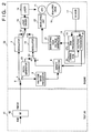
- Fig. 1 is a block diagram illustrating an example of the arrangement of a controller and engine in an image forming apparatus embodying the present invention
- Fig. 2 is a block diagram showing a case in which the engine of Fig. 1 is evaluated.
- numeral 31 denotes the controller and 32 the engine.
- the controller 31 includes an RF unit 1 for performing color conversion processing such as masking and UCR, a first halftone image processor 2 the output of which is supplied to an input terminal b of a switch 4 via a first density corrector 3, and a first patch pattern generator 5 connected to an input terminal a of the switch 4. It is thus possible to switch between density control and printing.
- the output of the switch 4 is supplied to a first modulator 7 via an output terminal a of switch 6 provided in the engine 32.
- the switch has another output terminal b connected to a second halftone image processor 8, the output of which is supplied to an input terminal b of a switch 10 via a second density corrector 9.
- a second patch pattern generator 23 is connected to an input terminal a of the switch 10 so that it is possible to switch between density control and printing.
- the output of the switch 10 is applied to a second modulator 11.
- the output of the first modulator 7 and the output of the second modulator 11 are selectively applied to laser driver 13 by a switch 12.
- a laser 14 Light emitted from a laser 14 is made to scan a photosensitive drum 15 by a scanner, not shown, thereby forming a latent image on the drum.
- the formed latent image is developed and is transferred either to a transfer drum 16 at the time of density control or to recorded paper, which has been wound upon the transfer drum 16, at the time of printing.
- the connections and arrangements of a density sensor 17, a Dmax processor 19 in a CPU 18, a developing high-voltage generator 21 and a developing unit 22 are similar to those of the prior art.
- the output of a halftone processor 20 within the CPU 18 is applied to the second density corrector 9 of the engine 32 and to the first density corrector 3 of the controller 31.
- numeral 41 denotes a test jig for evaluating the engine 32.
- the test jig 41 is provided with an RF unit 42 made to accommodate the engine process characteristics designated by the engine developer.
- a designated YMCK signal obtained by the RF unit 42 mounted on the test jig 41 is sent to the engine 32 field-sequentially as multivalued image data of, say, 200 lines.
- This signal is applied to the halftone image processor 8 via the contact b of the switch 6.
- the halftone image processor 8 performs superpixel processing for halftone printing of 200 lines, the output of the processor 8 is supplied to the modulator 11 via the density corrector 9 and switch 10, and the output of the modulator 11 is supplied to the laser driver 13 via the contact b of the switch 12.
- the modulator 11 is a central-growth pulse-width modulator in which growth occurs from the center of pixels in correspondence with 200 lines of superpixels.
- Fig. 3 is a block diagram illustrating an example of the detailed arrangement of the halftone image processor 8, a density corrector 9 and modulator 11.
- Multivalued image data Video 0 ⁇ 7 of, say, eight bits, outputted by the test jig 41 is latched in a latch 51 synchronized to an image clock VCLK.
- a latch 51 synchronized to an image clock VCLK.
- processing such as edge emphasis, not illustrated, may also be executed.
- a gamma-correction RAM 52 outputs image data obtained by subjecting the above-mentioned image data to a density correction by correction data from the halftone processor 20, described later.
- the image data corrected for density is latched in a latch 53 synchronized to VCLK.
- a clock generator 54 generates a clock signal SCLK having a frequency that is 512 times that of the image clock VCLK.
- a counter 55 counts the clock signal SCLK up or down. More specifically, since one input pixel has 256 gray levels, the counter counts up by 256 and then down by 256 in one period of the image clock VCLK. As a result, the output of the counter is a triangular wave ranging between "00" and "FF", as shown in the example of Fig. 4.
- a comparator 56 compares the outputs of the latch 53 and counter 55, thereby pulse-width modulating the image data after it is gamma-corrected.
- the laser driver 13 drives the laser 14 in dependence upon this pulse-width modulated signal, thereby forming dots which grow from the centers of pixels so that a halftone image can be reproduced.
- Density control will be described next. The density control is executed before actual printing takes place. Dmax control will be described first.
- Patch data having a prescribed shape created on the basis of a Dmax-control patch pattern that has been stored in the patch pattern generator 23 for the purpose of Dmax control is formed, as a latent image of a plurality of patch patterns, on the outer peripheral surface of the photosensitive drum 15 by the laser 14 through the intermediary of the contact a of switch 10, the pulse-width modulator 11 and the laser driver 13.
- the Dmax-control patch pattern has several gray levels in the vicinity of maximum density for each color corresponding to the recording paper.
- the developing high-voltage generator 21 generates developing bias at a plurality of levels, which vary in stepwise fashion, in correspondence with the number of patch patterns, whereby the above-mentioned latent image is visualized by the developing unit 22.
- This visual image is transferred to the recording paper on the transfer drum 16, and the density of the patch pattern corresponding to the developing bias is measured by the density sensor 17.
- the Dmax processor 19 in the CPU 18 subjects the measurement data to interpolation processing, calculates developing bias, at which maximum density is obtained, from the developing-bias - image density characteristic obtained, and sets a developing bias on the basis of the results of calculation, thereby holding the maximum density constant.
- Dmax control may be adapted to control other process conditions such as corona discharge voltage and fixing temperature.
- halftone control is executed.
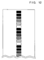
- Fig. 5 is a diagram illustrating patch formation on the transfer drum 16.
- Fig. 12 is a diagram illustrating the patches formed.
- Eight patch patterns 70 having a plurality of density levels for each color, which patterns have been generated on the basis of patch patterns for halftone control stored in the patch generator 23, are used to form a latent image on the photosensitive drum 15 in the same manner as in Dmax control. However, the latent image is visualized by the developing unit 22 while the developing bias is maintained at a prescribed value, and this image is transferred to the recording paper on the transfer drum 16.
- the transferred plurality of patch patterns each have their color density measured by the density sensor 17, and the resulting data is processed by the halftone processor 20 within the CPU 18.
- the halftone processor 20 obtains a density characteristic, an example of which is indicated at 72 in Fig.
- the halftone processor 20 calculates correction data by referring to a gamma table stored in a gamma ROM 24 and stores the correction data in the gamma correction RAM 52.
- the output data in the latch 51 is corrected by this correction data.
- density control performed by the engine namely Dmax control and halftone control, is carried out on the basis of control by the CPU 18 within the engine when the power supply starts up or periodically, by way of example.
- the gamma data is data for absorbing a density difference between the density detection point (the transfer drum 16) and the actual fixed image as well as a density difference caused by the environment.
- the environment mentioned here refers to temperature and/or humidity. Accordingly, a sensor for sensing temperature and/or humidity is provided within the engine and the output of the sensor is delivered to the controller.
- any YMCK signal obtained by the RF unit 1 is supplied field-sequentially to the halftone image processor 2 as multivalued image data of, say, 600 lines.
- the halftone image processor 2 forms superpixels by grouping each of the pixels, which are in units of 600 lines, every three pixels in the main-scan direction and supplies these to the density corrector 3 as six-bit image data and two-bit position information pixel by pixel.
- the output of the density corrector 3 is supplied to the engine 32 via the switch 4.
- the switch 4 is connected to the b side and the switch 6 is connected to the a side. Accordingly, the above-mentioned image data and position information are supplied to the modulator 7, whence the data and information are delivered to the laser driver 13 via the contact a of switch 12.
- the modulator 7 is a pulse-width modulator which, on the basis of, say, two-bit position information, is capable of selectively subjecting each pixel of 600 lines to central-growth pulse-width modulation in which pixels grow from the center thereof, left-growth pulse-width modulation in which pixels grow from the left side, and right-growth pulse-width modulation in which pixels grow from the right side.
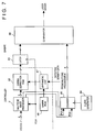
- Fig. 7 is a block diagram illustrating an example of a detailed arrangement of the halftone image processor 2, density corrector 3 and modulator 7. Switches are not necessary in this description of operation and therefore are not shown.
- the multivalued image data Video 0 ⁇ 7 of, say, eight bits from the RF unit 1 is converted to six-bit data and two-bit position information Pos0, Pos1 of each pixel by the halftone image processor 2.
- the six-bit data of each pixel is applied to gamma correction RAM 82, and the two-bit position information Pos0, Pos1 is applied to a counter 85 in the engine 32.
- the gamma correction RAM 82 outputs six-bit image data obtained by subjecting the entered six-bit data to a density correction using correction data from an arithmetic unit 87, described later.
- the image data whose density has been corrected is latched in a latch 83 synchronized to VCLK.
- a clock generator 84 generates a clock signal SCLK whose frequency is 128 times that of the image clock signal VCLK.
- a counter 85 counts the clock signal SCLK up or down. More specifically, since one input pixel has 64 gray levels, the counter counts up by 64 and then down by 64 in one period of the image clock VCLK in accordance with the position information signals Pos0, Pos1. As a result, the output value of the counter is a triangular wave 91 ranging between "00" and "3F", as shown in the example of Fig. 8. Further, a sawtooth waveform 92 which rises to the right and a sawtooth waveform 93 which decays to the right can also be generated by an up-count every two clocks.
- a comparator 86 compares the outputs of the latch 83 and counter 85, thereby pulse-width modulating the image data after it is gamma-corrected.
- the laser driver 13 drives the laser 14 in dependence upon this pulse-width modulated signal.
- Density control will be described next. Density control is performed in a manner similar to that set forth above.
- Eight patch patterns 70 which have been generated by the patch generator 5, are formed for each color on the transfer drum 16 by a sequence already described. Moreover, the patch pattern data for 600 lines generated by the patch generator 5 is transmitted to the first modulator 7 via the input terminal a of the switch 4 and the output terminal a of the switch 6, thereby the modulator 7 modulates the patch data.
- the patch pattern data takes on different values because the halftone image processing is different from that of the method described above.
- the patch patterns each have their color density measured by the density sensor 17, and the resulting data is processed by the halftone processor 20 within the CPU 18.
- the halftone processor 20 obtains a density characteristic, an example of which is indicated at 72 in Fig. 6, by interpolation processing based upon the eight items of data. This is set to the density corrector 3 of the controller 31 as density data. There are cases in which these characteristics also differ from those of the foregoing method.
- the arithmetic unit 87 calculates correction data by referring to a gamma table stored in a gamma ROM 88 and stores the correction data in the gamma correction RAM 82.
- the output data of the halftone image processor 2 is corrected by this correction data.
- the developer of the engine initiates automatic density control, which is brought to conclusion within the engine, premised on image processing inside the engine, and performs evaluation based upon a multivalued image signal from the RF unit made to correspond to the process characteristics of the engine.
- automatic density control which is brought to conclusion within the engine, premised on image processing inside the engine, and performs evaluation based upon a multivalued image signal from the RF unit made to correspond to the process characteristics of the engine.
- the developer of the controller is capable of providing the controller with functions of its own by performing automatic density control spanning the controller and the engine, using the density detection signal from the engine, on the condition of image processing within the controller.
- the developer of the controller may ascertain the process characteristics of the engine, thereby making it possible to raise the degree of freedom and shorten development time.
- control of density is not performed merely by a fixed method but by using a controller on the basis of a prescribed image pattern that has been subjected to image processing.
- image density characteristics to be adjusted are not fixed and image formation can be carried out based upon optimum density characteristics flexibly conforming to the user needs. This makes it possible to obtain a high-quality output image under various environmental condition or in image processing methods.
- Fig. 9 is a block diagram showing an example of an arrangement according to a modification of the present invention.
- the controller 31 includes a first pseudo-halftone processor 101 for executing image processing by the dither method, for example, and the engine 32 includes a second pseudo-halftone processor 102 for executing image processing by the error diffusion method, for example.
- the first density corrector 3 and first modulator 7 are optimized for the dither method
- the second density corrector 9 and second modulator 11 are optimized for the error diffusion method.
- pseudo-halftones but also a binary image may be subjected to smoothing by the controller 31 and edge emphasis by the engine 32.
- types of image processing inclusive of the processing of the first embodiment may be combined freely.
- Fig. 10 is a block diagram showing an example of an arrangement according to another modification of the present invention.
- the controller 31 has a gamma RAM 111 instead of the gamma ROM in order to download a gamma table from a host computer or the like.
- Fig. 11 is a block diagram showing an example of an arrangement according to the modification.
- the switches 6 and 12 are changed over every pixel by a signal IMCHR 121 showing the attributes of an image.
- patch data from a patch generator does not undergo corresponding image processing.
- the patch data can be sent through an image processor as a matter of course.
- the controller also is capable executing image processing of its own.
- a variety of controllers can be made to accommodate one type of engine so that a greater variety of printers can be used.
- printing quality can be improved by effectively using two modulators made to accommodate the image processing of each of the controller and engine units.
- the present invention can be applied to a system constituted by a plurality of devices or to an apparatus comprising a single device. Furthermore, it goes without saying that the invention is applicable also to a case where the object of the invention is attained by supplying a program to a system or apparatus.
- an image forming apparatus and method in which a controller is capable of executing image processing of its own. This makes it possible to solve the problem of prolonged development time, the problem wherein image processing functions inclusive of color conversion cannot be added on freely, and the problem wherein engine quality cannot be assured in a case where image processing functions are allowed to be added on freely.
- the following description relates to density control based upon control performed by the controller.
- Fig. 14 density control is carried out using video interface lines between the controller and the engine, namely a command signal line 27 for transmitting eight-bit serial signal in order to designate various operations in the engine, a status signal line 25 for receiving an eight-bit serial signal in order to ascertain the status of the engine, an eight-bit parallel data signal line for transmitting print data to the engine, and a top signal line 26 which the engine uses to request image data.
- a command signal line 27 for transmitting eight-bit serial signal in order to designate various operations in the engine
- a status signal line 25 for receiving an eight-bit serial signal in order to ascertain the status of the engine
- an eight-bit parallel data signal line for transmitting print data to the engine
- a top signal line 26 which the engine uses to request image data.
- a CPU 28 within the controller 31 sends a density-measurement execution command to the engine 32 via the command line when density control is required (S1).
- the engine 32 finishes Dmax control within the engine (S2).
- the engine 32 uses the top signal line to request the controller 31 to transmit image data (S3).
- the CPU of the controller 31 changes the switch 4 over to the side (a) of the patch pattern generator 5 and sends, say, eight items of patch pattern data for each color to the engine 32 via the data signal line (S4).
- the engine 32 thenceforth forms each of the patch patterns on the transfer drum through a sequence similar to that described above (S5), measures the density of each color by the density sensor 17, stores the measured densities in a memory (not shown) within the halftone processor (S6) and returns a status signal indicating end of density measurement to the controller 31 via the status line (S7).
- the controller 31 Upon receiving the status signal indicating end of density measurement, the controller 31 sends the engine 32 a designated density-patch request command via the command signal line in order to ascertain the number of a patch (one among eight patterns for each color) corresponding to density data sent from the engine (S8). Upon receiving this command, the engine 32 sends the designated patch number back to the controller 31 via the status signal line (S9).
- the engine 32 reads the density data of the designated patch out of the memory and sends back the data, via the status signal line, as the result of density measurement (S11).
- the controller 31 obtains a density characteristic, of the kind illustrated at 72 in Fig. 6, from eight items of data for each color by means of interpolation processing using the halftone processor within the CPU, and sends this density characteristic to the density corrector 3 of controller 31 as density data (S12).
- density control in the engine 32 is periodically performed, which is independent from the above-mentioned density control in the controller 31.
- an image forming at 200 lines which is automatically controlled by the engine 32 guarantees the same color forming as that when the apparatus is shipped.
- an image forming at 600 lines is controlled by the controller 31, thus providing a color forming depending on a usage of the image.
- Fig. 16 is a block diagram showing an example of the arrangement of the controller and engine in an image forming apparatus according to this modification of the invention.
- a wake-up signal from a wake-up sensor 45, a door-open signal from a door-open sensor 46 and a toner signal, which indicates whether or not there is any toner, from a remaining-toner sensor 47 are connected to ports of the CPU 18.
- a signal 48 indicating completion of Dmax control within the engine and a signal 49 indicting completion of halftone control within the engine are sent to the controller 31 as status signals via a status processor 44.
- the controller 31 sends a density-control execute status request command to the engine 32 via a command line at a prescribed period.
- the engine 32 sends a density-control execute status signal back to the controller 31 via the status line.
- This status signal indicates power-on, door open, remaining amount of toner, completion of Dmax control within the engine and completion of halftone control within the engine, etc.
- the controller 31 senses wake-up (restoration from a sleep mode) or door open (as when jamming occurs), which are factors causing an environmental change within the engine. If the amount of remaining toner is adequate, the controller 31 shifts to density-control execution.
- the controller 31 does not execute density control because such control cannot be performed accurately under such conditions.
- Dmax control from the controller 31 is skipped and control starts from halftone control.
- the signal indicating completion of Dmax control and the signal indicating completion of halftone control are used as control status signals within the engine.
- a signal indicating that execution of Dmax control is in progress or a signal indicating that execution of halftone control is in progress may be used together with these signals.
- wake-up sensing means a door-open sensing means and residual-toner sensing means, which is used to determine whether performing density control is meaningful or not, are employed to sense a change in the status of an engine for which there is a possibility that density control is necessary.
- signals indicating status of density control execution by the engine itself namely a signal indicating completion of Dmax control within the engine and a signal indicating completion of halftone control within the engine are sent to a controller.
- the controller is capable of appropriately judging the timing at which density control should be executed, thus making highly precise control of density possible.
- waiting time until printing begins can be shortened because the foregoing need not be performed redundantly with regard to density control requests from both the controller and engine.
- S8 ⁇ S11 shown in Fig. 15 may be converted to a step of issuing a command for designating a density patch number, a step of issuing a command requesting the results of density measurement, and a step of receiving, in the form of a status signal, results of density measurement of the designated density patch number.
- an arrangement may be adopted in which the controller determines whether Dmax control is to be performed or not.
- the controller determines whether Dmax control is to be performed or not.
- the command (S1) for executing measurement of density in Fig. 15 an arrangement may be adopted in which it is possible to designate whether Dmax control is to be performed or not.
- a case in which Dmax control is passed may start from S4.
- an arrangement may be adopted in which whether or not Dmax control is to be performed is judged by the controller based upon a status signal from the engine. Specifically, an arrangement may be adopted in which when Dmax control was performed is indicated by a status signal, with the controller making the judgment based upon elapsed time from the previous Dmax control event.
- an LBP is employed in the foregoing embodiments, this does not impose a limitation upon the present invention.
- an image processing apparatus in which an image is formed by employing a head of the type in which film boiling is produced by thermal energy so as to jet droplets of ink.
- controller in each of the foregoing embodiments may reside in a host device such as an external apparatus.
- an input signal may be processed to pass through the halftone image processer 2 and the density corrector 3 in the controller 31.
- each of the halftone image processer 2 and the density corrector 3 provides a halftone image processing at 200 and 600 lines and a density correction for 200 and 600 lines.
- the halftone image processing and the density correction for 200 lines and these processing and correction for 600 lines are switched over properly.
- it may also be arranged that a density control for both 600 lines and 200 lines in accordance with a control of the controller 31 by holding the patch data for 600 and 200 lines in the patch generator 5.
Landscapes
- Engineering & Computer Science (AREA)
- Multimedia (AREA)
- Signal Processing (AREA)
- Facsimile Image Signal Circuits (AREA)
- Color, Gradation (AREA)
- Image Processing (AREA)
- Color Image Communication Systems (AREA)
- Developing For Electrophotography (AREA)
- Control Or Security For Electrophotography (AREA)
- Color Electrophotography (AREA)
Applications Claiming Priority (6)
| Application Number | Priority Date | Filing Date | Title |
|---|---|---|---|
| JP10785694 | 1994-04-22 | ||
| JP10785694 | 1994-04-22 | ||
| JP107856/94 | 1994-04-22 | ||
| JP92385/95 | 1995-04-18 | ||
| JP09238595A JP3703162B2 (ja) | 1994-04-22 | 1995-04-18 | 画像形成装置 |
| JP9238595 | 1995-04-18 |
Publications (3)
| Publication Number | Publication Date |
|---|---|
| EP0679016A2 true EP0679016A2 (fr) | 1995-10-25 |
| EP0679016A3 EP0679016A3 (fr) | 1996-04-24 |
| EP0679016B1 EP0679016B1 (fr) | 2001-08-01 |
Family
ID=26433826
Family Applications (1)
| Application Number | Title | Priority Date | Filing Date |
|---|---|---|---|
| EP95302679A Expired - Lifetime EP0679016B1 (fr) | 1994-04-22 | 1995-04-21 | Procédé et commande de traitement d'images |
Country Status (5)
| Country | Link |
|---|---|
| US (1) | US6111664A (fr) |
| EP (1) | EP0679016B1 (fr) |
| JP (1) | JP3703162B2 (fr) |
| DE (1) | DE69521930T2 (fr) |
| HK (1) | HK1012147A1 (fr) |
Cited By (5)
| Publication number | Priority date | Publication date | Assignee | Title |
|---|---|---|---|---|
| EP0804014A1 (fr) * | 1996-04-26 | 1997-10-29 | Konica Corporation | Imprimante à laser à résolution variable |
| WO1998056804A1 (fr) * | 1997-06-13 | 1998-12-17 | Human Genome Sciences, Inc. | 86 proteines secretees humaines |
| US5950036A (en) * | 1996-08-23 | 1999-09-07 | Canon Kabushiki Kaisha | Image processing apparatus having calibration control and related method |
| US6046820A (en) * | 1996-10-22 | 2000-04-04 | Canon Kabushiki Kaisha | Image forming device and computer which share the generation of a function for correcting image data based on an image forming condition of the image forming device |
| US6122461A (en) * | 1997-06-26 | 2000-09-19 | Canon Kabushiki Kaisha | Image processing apparatus and control method therefor |
Families Citing this family (10)
| Publication number | Priority date | Publication date | Assignee | Title |
|---|---|---|---|---|
| JPH11289454A (ja) | 1997-11-28 | 1999-10-19 | Canon Inc | 画像処理方法および画像処理装置およびコンピュータが読み出し可能なプログラムを格納した記憶媒体 |
| JP3787427B2 (ja) | 1997-11-28 | 2006-06-21 | キヤノン株式会社 | プリンタサーバのデータ処理方法及び記憶媒体 |
| JP3603766B2 (ja) * | 1999-12-22 | 2004-12-22 | セイコーエプソン株式会社 | 電子写真の画像処理装置及びそれを利用した電子写真装置 |
| US7038811B1 (en) * | 2000-03-31 | 2006-05-02 | Canon Kabushiki Kaisha | Standardized device characterization |
| JP2002072609A (ja) * | 2000-08-31 | 2002-03-12 | Canon Inc | 画像形成装置 |
| JP2002202646A (ja) * | 2000-12-28 | 2002-07-19 | Canon Inc | 画像処理装置およびその制御方法 |
| JP4708908B2 (ja) * | 2004-08-20 | 2011-06-22 | キヤノン株式会社 | 画像形成装置及び画像形成方法 |
| JP2007036370A (ja) * | 2005-07-22 | 2007-02-08 | Brother Ind Ltd | 画像形成システム、画像形成装置、及びデータ処理装置 |
| JP2007081750A (ja) * | 2005-09-13 | 2007-03-29 | Canon Inc | 画像形成装置及びその方法、並びにプログラム |
| JP2022175853A (ja) | 2021-05-14 | 2022-11-25 | キヤノン株式会社 | 画像形成装置 |
Citations (2)
| Publication number | Priority date | Publication date | Assignee | Title |
|---|---|---|---|---|
| WO1991002427A1 (fr) * | 1989-08-02 | 1991-02-21 | Eastman Kodak Company | Procede et appareil associe de calibrage d'un dispositif d'impression numerique sur papier couleur |
| EP0484900A1 (fr) * | 1990-11-09 | 1992-05-13 | Mitsubishi Denki Kabushiki Kaisha | Méthode et appareil pour modifier la densité des couleurs dans une imprimante |
Family Cites Families (7)
| Publication number | Priority date | Publication date | Assignee | Title |
|---|---|---|---|---|
| DE3787611T2 (de) * | 1986-10-29 | 1994-03-24 | Canon Kk | Farbbildlesegerät oder Farbbilderzeugungsgerät. |
| DE69030701T2 (de) * | 1989-10-02 | 1997-10-02 | Canon Kk | Bilderzeugungsgerät und Modulationsverfahren |
| EP0454088B1 (fr) * | 1990-04-25 | 1998-07-01 | Canon Kabushiki Kaisha | Appareil de traitement d'images |
| US5276459A (en) * | 1990-04-27 | 1994-01-04 | Canon Kabushiki Kaisha | Recording apparatus for performing uniform density image recording utilizing plural types of recording heads |
| US5828780A (en) * | 1993-12-21 | 1998-10-27 | Ricoh Company, Ltd. | Image processing apparatus with improved color correction |
| US5731823A (en) * | 1994-01-27 | 1998-03-24 | Hewlett-Packard Company | Automatic optimization of hardcopy output for enhanced appearance and throughput |
| US5594557A (en) * | 1994-10-03 | 1997-01-14 | Xerox Corporation | Color printer calibration correcting for local printer non-linearities |
-
1995
- 1995-04-18 JP JP09238595A patent/JP3703162B2/ja not_active Expired - Fee Related
- 1995-04-21 EP EP95302679A patent/EP0679016B1/fr not_active Expired - Lifetime
- 1995-04-21 DE DE69521930T patent/DE69521930T2/de not_active Expired - Lifetime
-
1997
- 1997-12-12 US US08/989,683 patent/US6111664A/en not_active Expired - Lifetime
-
1998
- 1998-12-10 HK HK98113122A patent/HK1012147A1/xx not_active IP Right Cessation
Patent Citations (2)
| Publication number | Priority date | Publication date | Assignee | Title |
|---|---|---|---|---|
| WO1991002427A1 (fr) * | 1989-08-02 | 1991-02-21 | Eastman Kodak Company | Procede et appareil associe de calibrage d'un dispositif d'impression numerique sur papier couleur |
| EP0484900A1 (fr) * | 1990-11-09 | 1992-05-13 | Mitsubishi Denki Kabushiki Kaisha | Méthode et appareil pour modifier la densité des couleurs dans une imprimante |
Cited By (5)
| Publication number | Priority date | Publication date | Assignee | Title |
|---|---|---|---|---|
| EP0804014A1 (fr) * | 1996-04-26 | 1997-10-29 | Konica Corporation | Imprimante à laser à résolution variable |
| US5950036A (en) * | 1996-08-23 | 1999-09-07 | Canon Kabushiki Kaisha | Image processing apparatus having calibration control and related method |
| US6046820A (en) * | 1996-10-22 | 2000-04-04 | Canon Kabushiki Kaisha | Image forming device and computer which share the generation of a function for correcting image data based on an image forming condition of the image forming device |
| WO1998056804A1 (fr) * | 1997-06-13 | 1998-12-17 | Human Genome Sciences, Inc. | 86 proteines secretees humaines |
| US6122461A (en) * | 1997-06-26 | 2000-09-19 | Canon Kabushiki Kaisha | Image processing apparatus and control method therefor |
Also Published As
| Publication number | Publication date |
|---|---|
| EP0679016B1 (fr) | 2001-08-01 |
| US6111664A (en) | 2000-08-29 |
| DE69521930D1 (de) | 2001-09-06 |
| EP0679016A3 (fr) | 1996-04-24 |
| DE69521930T2 (de) | 2001-12-20 |
| JP3703162B2 (ja) | 2005-10-05 |
| HK1012147A1 (en) | 1999-07-23 |
| JPH089158A (ja) | 1996-01-12 |
Similar Documents
| Publication | Publication Date | Title |
|---|---|---|
| EP0679016B1 (fr) | Procédé et commande de traitement d'images | |
| US7230739B2 (en) | Image processing apparatus and method | |
| US20010043258A1 (en) | Correction control for image forming apparatus and method | |
| US6148158A (en) | Image processing apparatus and method having a plurality of image forming units for performing image formation using predetermined colors | |
| JPH1169157A (ja) | 画像形成装置 | |
| US5212560A (en) | Electrophotographic image forming apparatus comprising means for automatically adjusting image reproduction density | |
| JPH1188690A (ja) | 画像処理装置及び画像処理方法 | |
| US7031020B1 (en) | Image processing method, apparatus and controller | |
| JPH05333652A (ja) | 画像形成装置 | |
| EP0720349B1 (fr) | Appareil et procédé de traitement d'images | |
| JPH08337007A (ja) | 画像処理装置及び方法 | |
| JPH08156330A (ja) | 画像形成装置 | |
| EP0327278B1 (fr) | Dispositif pour la formation d'images en couleurs et procédé et dispositif de traitement d'images en couleurs | |
| EP0622948B1 (fr) | Dispositif et méthode de traitement d'image | |
| US6538683B2 (en) | Image forming apparatus and a control method of an image forming apparatus | |
| JP3472257B2 (ja) | 画像処理方法、記録媒体 | |
| JPH09154020A (ja) | 画像処理装置及び方法 | |
| US6075904A (en) | Image processing apparatus and method which prevents the generation of a white stripe on an output image | |
| JPH1013675A (ja) | 画像処理装置及びその方法、及びコントローラ | |
| JPH0774972A (ja) | 画像形成装置 | |
| JP3710224B2 (ja) | 画像処理装置及び方法 | |
| JPH10171219A (ja) | 画像形成装置 | |
| JPH0884266A (ja) | 画像形成装置 | |
| JPH0799588A (ja) | 画像形成装置 | |
| JP2002142112A (ja) | 画像処理方法及び装置、並びに画像形成方法及び装置 |
Legal Events
| Date | Code | Title | Description |
|---|---|---|---|
| PUAI | Public reference made under article 153(3) epc to a published international application that has entered the european phase |
Free format text: ORIGINAL CODE: 0009012 |
|
| AK | Designated contracting states |
Kind code of ref document: A2 Designated state(s): DE ES FR GB IT NL |
|
| PUAL | Search report despatched |
Free format text: ORIGINAL CODE: 0009013 |
|
| AK | Designated contracting states |
Kind code of ref document: A3 Designated state(s): DE ES FR GB IT NL |
|
| 17P | Request for examination filed |
Effective date: 19960904 |
|
| 17Q | First examination report despatched |
Effective date: 19980522 |
|
| RTI1 | Title (correction) |
Free format text: IMAGE PROCESSING METHOD AND CONTROLLER |
|
| GRAG | Despatch of communication of intention to grant |
Free format text: ORIGINAL CODE: EPIDOS AGRA |
|
| RTI1 | Title (correction) |
Free format text: IMAGE PROCESSING METHOD AND CONTROLLER |
|
| GRAG | Despatch of communication of intention to grant |
Free format text: ORIGINAL CODE: EPIDOS AGRA |
|
| GRAH | Despatch of communication of intention to grant a patent |
Free format text: ORIGINAL CODE: EPIDOS IGRA |
|
| GRAH | Despatch of communication of intention to grant a patent |
Free format text: ORIGINAL CODE: EPIDOS IGRA |
|
| GRAA | (expected) grant |
Free format text: ORIGINAL CODE: 0009210 |
|
| AK | Designated contracting states |
Kind code of ref document: B1 Designated state(s): DE ES FR GB IT NL |
|
| PG25 | Lapsed in a contracting state [announced via postgrant information from national office to epo] |
Ref country code: NL Free format text: LAPSE BECAUSE OF FAILURE TO SUBMIT A TRANSLATION OF THE DESCRIPTION OR TO PAY THE FEE WITHIN THE PRESCRIBED TIME-LIMIT Effective date: 20010801 Ref country code: IT Free format text: LAPSE BECAUSE OF FAILURE TO SUBMIT A TRANSLATION OF THE DESCRIPTION OR TO PAY THE FEE WITHIN THE PRESCRIBED TIME-LIMIT;WARNING: LAPSES OF ITALIAN PATENTS WITH EFFECTIVE DATE BEFORE 2007 MAY HAVE OCCURRED AT ANY TIME BEFORE 2007. THE CORRECT EFFECTIVE DATE MAY BE DIFFERENT FROM THE ONE RECORDED. Effective date: 20010801 Ref country code: FR Free format text: LAPSE BECAUSE OF FAILURE TO SUBMIT A TRANSLATION OF THE DESCRIPTION OR TO PAY THE FEE WITHIN THE PRESCRIBED TIME-LIMIT Effective date: 20010801 |
|
| REF | Corresponds to: |
Ref document number: 69521930 Country of ref document: DE Date of ref document: 20010906 |
|
| EN | Fr: translation not filed | ||
| REG | Reference to a national code |
Ref country code: GB Ref legal event code: IF02 |
|
| NLV1 | Nl: lapsed or annulled due to failure to fulfill the requirements of art. 29p and 29m of the patents act | ||
| PG25 | Lapsed in a contracting state [announced via postgrant information from national office to epo] |
Ref country code: ES Free format text: LAPSE BECAUSE OF FAILURE TO SUBMIT A TRANSLATION OF THE DESCRIPTION OR TO PAY THE FEE WITHIN THE PRESCRIBED TIME-LIMIT Effective date: 20020228 |
|
| PLBE | No opposition filed within time limit |
Free format text: ORIGINAL CODE: 0009261 |
|
| STAA | Information on the status of an ep patent application or granted ep patent |
Free format text: STATUS: NO OPPOSITION FILED WITHIN TIME LIMIT |
|
| 26N | No opposition filed | ||
| PGFP | Annual fee paid to national office [announced via postgrant information from national office to epo] |
Ref country code: GB Payment date: 20140414 Year of fee payment: 20 |
|
| PGFP | Annual fee paid to national office [announced via postgrant information from national office to epo] |
Ref country code: DE Payment date: 20140430 Year of fee payment: 20 |
|
| REG | Reference to a national code |
Ref country code: DE Ref legal event code: R071 Ref document number: 69521930 Country of ref document: DE |
|
| REG | Reference to a national code |
Ref country code: GB Ref legal event code: PE20 Expiry date: 20150420 |
|
| PG25 | Lapsed in a contracting state [announced via postgrant information from national office to epo] |
Ref country code: GB Free format text: LAPSE BECAUSE OF EXPIRATION OF PROTECTION Effective date: 20150420 |