EP0678583B1 - Procédé d'extraction solide-liquide et tour d'extraction pour la mise en oeuvre du procédé - Google Patents
Procédé d'extraction solide-liquide et tour d'extraction pour la mise en oeuvre du procédé Download PDFInfo
- Publication number
- EP0678583B1 EP0678583B1 EP94105491A EP94105491A EP0678583B1 EP 0678583 B1 EP0678583 B1 EP 0678583B1 EP 94105491 A EP94105491 A EP 94105491A EP 94105491 A EP94105491 A EP 94105491A EP 0678583 B1 EP0678583 B1 EP 0678583B1
- Authority
- EP
- European Patent Office
- Prior art keywords
- juice
- extraction tower
- extraction
- tower
- wall
- Prior art date
- Legal status (The legal status is an assumption and is not a legal conclusion. Google has not performed a legal analysis and makes no representation as to the accuracy of the status listed.)
- Expired - Lifetime
Links
- 238000000605 extraction Methods 0.000 title claims description 91
- 238000000034 method Methods 0.000 title claims description 22
- 238000000956 solid--liquid extraction Methods 0.000 title claims description 14
- 235000011389 fruit/vegetable juice Nutrition 0.000 claims description 131
- 239000007787 solid Substances 0.000 claims description 49
- 235000016068 Berberis vulgaris Nutrition 0.000 claims description 30
- 241000335053 Beta vulgaris Species 0.000 claims description 30
- CZMRCDWAGMRECN-UGDNZRGBSA-N Sucrose Chemical compound O[C@H]1[C@H](O)[C@@H](CO)O[C@@]1(CO)O[C@@H]1[C@H](O)[C@@H](O)[C@H](O)[C@@H](CO)O1 CZMRCDWAGMRECN-UGDNZRGBSA-N 0.000 claims description 9
- 229930006000 Sucrose Natural products 0.000 claims description 9
- 239000005720 sucrose Substances 0.000 claims description 9
- 239000004576 sand Substances 0.000 claims description 7
- 230000001105 regulatory effect Effects 0.000 claims description 6
- 239000000470 constituent Substances 0.000 claims description 5
- 230000000903 blocking effect Effects 0.000 claims description 4
- 238000004140 cleaning Methods 0.000 claims description 3
- 230000009969 flowable effect Effects 0.000 claims 3
- 230000008021 deposition Effects 0.000 claims 1
- 239000013505 freshwater Substances 0.000 description 7
- 239000000203 mixture Substances 0.000 description 7
- 238000010276 construction Methods 0.000 description 6
- 208000015181 infectious disease Diseases 0.000 description 6
- 238000003466 welding Methods 0.000 description 6
- 239000000945 filler Substances 0.000 description 5
- 239000007788 liquid Substances 0.000 description 5
- 125000006850 spacer group Chemical group 0.000 description 3
- XLYOFNOQVPJJNP-UHFFFAOYSA-N water Substances O XLYOFNOQVPJJNP-UHFFFAOYSA-N 0.000 description 3
- 241000219310 Beta vulgaris subsp. vulgaris Species 0.000 description 2
- 235000021536 Sugar beet Nutrition 0.000 description 2
- 230000000694 effects Effects 0.000 description 2
- 238000010438 heat treatment Methods 0.000 description 2
- 239000002184 metal Substances 0.000 description 2
- 238000003825 pressing Methods 0.000 description 2
- 238000003756 stirring Methods 0.000 description 2
- 240000000111 Saccharum officinarum Species 0.000 description 1
- 235000007201 Saccharum officinarum Nutrition 0.000 description 1
- 239000000969 carrier Substances 0.000 description 1
- 239000001913 cellulose Substances 0.000 description 1
- 229920002678 cellulose Polymers 0.000 description 1
- 238000005352 clarification Methods 0.000 description 1
- 238000011161 development Methods 0.000 description 1
- 230000018109 developmental process Effects 0.000 description 1
- 238000010586 diagram Methods 0.000 description 1
- 230000007717 exclusion Effects 0.000 description 1
- 230000002349 favourable effect Effects 0.000 description 1
- 238000011010 flushing procedure Methods 0.000 description 1
- 238000009434 installation Methods 0.000 description 1
- 239000002245 particle Substances 0.000 description 1
- 238000005086 pumping Methods 0.000 description 1
- 238000004064 recycling Methods 0.000 description 1
- 238000007789 sealing Methods 0.000 description 1
- 238000005476 soldering Methods 0.000 description 1
- 239000000126 substance Substances 0.000 description 1
Images


Classifications
-
- C—CHEMISTRY; METALLURGY
- C13—SUGAR INDUSTRY
- C13B—PRODUCTION OF SUCROSE; APPARATUS SPECIALLY ADAPTED THEREFOR
- C13B10/00—Production of sugar juices
- C13B10/02—Expressing juice from sugar cane or similar material, e.g. sorghum saccharatum
- C13B10/06—Sugar-cane crushers
-
- B—PERFORMING OPERATIONS; TRANSPORTING
- B01—PHYSICAL OR CHEMICAL PROCESSES OR APPARATUS IN GENERAL
- B01D—SEPARATION
- B01D11/00—Solvent extraction
- B01D11/02—Solvent extraction of solids
- B01D11/0215—Solid material in other stationary receptacles
- B01D11/0223—Moving bed of solid material
- B01D11/0226—Moving bed of solid material with the general transport direction of the solids parallel to the rotation axis of the conveyor, e.g. worm
-
- C—CHEMISTRY; METALLURGY
- C13—SUGAR INDUSTRY
- C13B—PRODUCTION OF SUCROSE; APPARATUS SPECIALLY ADAPTED THEREFOR
- C13B10/00—Production of sugar juices
- C13B10/08—Extraction of sugar from sugar beet with water
- C13B10/10—Continuous processes
- C13B10/102—Continuous processes having rotatable means for agitation or transportation
-
- C—CHEMISTRY; METALLURGY
- C13—SUGAR INDUSTRY
- C13B—PRODUCTION OF SUCROSE; APPARATUS SPECIALLY ADAPTED THEREFOR
- C13B10/00—Production of sugar juices
- C13B10/08—Extraction of sugar from sugar beet with water
- C13B10/12—Details of extraction apparatus, e.g. arrangements of pipes or valves
-
- B—PERFORMING OPERATIONS; TRANSPORTING
- B01—PHYSICAL OR CHEMICAL PROCESSES OR APPARATUS IN GENERAL
- B01D—SEPARATION
- B01D11/00—Solvent extraction
- B01D2011/002—Counter-current extraction
Definitions
- the invention relates to a method for solid-liquid extraction, in particular sucrose from beet pulp, with countercurrent extraction in an extraction tower from which tower juice is drawn off via sieves, and an extraction tower for carrying out the method.
- the extraction tower includes a central shaft with transport blades for transporting the beet pulp inside the tower and various nozzles for the supply and discharge of liquids and solid components, such as beet pulp.
- the sugar is extracted from the beet pulp with the exclusion of air in a countercurrent process.
- the beet pulp is fed countercurrent to the press and fresh water.
- the pressed and fresh water removes sucrose and other soluble substances from the beet pulp.
- the press water is created by squeezing beet pulp.
- the fresh water is a mixture of hot and cold water.
- the extraction tower and a countercurrent pulp mash are used in combination.
- the sucrose is released from the beet pulp.
- a water-like liquid, enriched with sucrose is created, the so-called tower juice.
- the so-called pulp arises as an extraction residue from the beet pulp. It is the pulp of the beet and can be removed through a nozzle arranged at the top of the extraction tower. The extraction of the tower sap from the extraction tower takes place mainly via a bottom sieve and sometimes also through side sieves.
- the extracted tower juice is passed over sand separators, which free the juice from any solid components that may still be contained in the tower juice, such as sand and earth from the raw beets. These solid components are not removed during the extraction of sucrose in the extraction tower, but are drawn off together with the tower juice.
- the tower juice is then usually fed to a countercurrent pulp mash.
- the bottom sieve used in the known extraction towers is supported centrally, and a mixture of beet pulp and raw juice can be pumped into the extraction tower through a lateral opening of the central support.
- the bottom sieve extends over the largest part of the tower jacket diameter and is usually composed of partial sieves.
- wipers are connected to the rotating shaft, which constantly slide over the bottom sieve and loosen the solids from the sieve and feed them back to the transport path.
- the invention has for its object to provide an improved method and an improved extraction tower for solid-liquid extraction, in particular the sucrose from beet pulp, with countercurrent extraction in an extraction tower from which tower juice is drawn off via sieves.
- the bottom strainer previously used is namely replaced in the invention by an essentially closed, stable and rigid bottom part, which in turn enables the use of an optimal stand frame.
- an extraction tower for solid-liquid extraction in which the tower juice and the small-sized solid components contained therein, hereinafter referred to as solids, are drawn off essentially via side screens.
- Small-sized solids mean, for example, sand when extracting sugar beet.
- the extraction of the tower sap essentially only via the side screens is in complete contrast to known processes in which side screen elements essentially perform auxiliary functions.
- the tower juice is withdrawn from the extraction tower at a predetermined speed. This means that the withdrawal speed can be preset manually or can be adjusted according to the extraction process.
- the withdrawal speed can be set, for example, via valves or slide elements when regulating the extraction process.
- An automatic, e.g. electrical, hydraulic etc., readjustment can be used.
- Solid-liquid extraction solids if they are small enough, are drawn off with the tower juice over the side screens. Larger components and smaller components not carried away by the tower sap sink to the bottom. The solid components are constantly whirled up in the tower sap by measures which occur or are brought about in the extraction tower in the base area and in the area of the side screens. As a result, the smaller components that have already settled can be taken away again with the tower juice to be removed.
- the turbulence in the floor area is caused, on the one hand, by transport vanes arranged on a central shaft for the transport, for example, of the beet pulp in countercurrent to the pressing and pressing operations introduced further up the extraction tower Fresh water. On the other hand, they are excited by wipers.
- this residual amount of the solids which has flowed past the side screens can be collected in the load-bearing bottom, for example in specially provided pockets.
- the solids can be removed from these pockets or from this base part.
- the solids that are drawn off via the side screens are connected to the tower sap in an emulsion-like manner.
- the residual solids can be removed from the bottom part manually or automatically via bottom openings.
- the invention is not only applicable in the recycling of sugar beet or sugar cane, but also for other products such as oil-containing products, cellulose, paper or the like.
- the extraction tower has a cylindrical outer frame 1. On this outer frame 1, two filler neck levels 2, 3 arranged one above the other are flanged for the introduction of pressurized and fresh water. Each level has several nozzles.
- transport vanes 4 are arranged on a shaft W, which cooperate with retainers 4a in order to achieve an axial transport movement of the chips.
- the transport wings 4 and 4a are only indicated.
- the retainers 4a are arranged on an outer wall 25 of the outer frame 1, the transport blades on the central shaft W of the extraction tower. Usually several levels of such transport wings 4 and 4a are used.
- the transport wing 4 and retainer 4a are used, for example, to transport beet pulp in counterflow to press and / or fresh water.
- the shaft W is driven by one or more electrically or hydraulically operated motors M driven. These can be arranged centrally or distributed and connected to the shaft W, for example via a gear, a ring gear or the like.
- the outer frame 1 is connected to a bottom part 5 on its underside. It is used, for example, or is encased by the outer frame 1 and optionally supported by supports 5a, which are welded to the outer frame 1, for example.
- the outer frame 1 of the extraction tower rests on one or more stand frames 6, 6a or the like.
- the inner stand frame 6a supports the base part 5, so that it does not bend with large tower diameters.
- the walls of the two frames 1 and 6 lie one on top of the other, the base part 5 and the higher outer frame parts being successively built up on the prepared stand frames 6, 6a.
- the junction of the two frames 1, 6 is created by means of walls 40, which can be flanges, for example.
- the two frames 1.6 can be connected to one another by means of screws or also by welding.
- a filler neck 8 for the mixture of, for example, beet pulp and tower juice is arranged in an opening 7 in the base part 5.
- the mixture of beet pulp and juice is fed in counter to the direction of rotation of the transport vanes 4 on the shaft W.
- the filler neck 8 is preferably obliquely in the bottom part 5 between the shaft W with the transport vanes 4 and the outer wall 25 of the outer frame 1 of the extraction tower provided with the pickups 4a arranged there.
- the filler neck 8 is arranged so that the bottom part 5 is not weakened. This is achieved, for example, by means of appropriate apparatus-technical design of the wall thicknesses.
- the filler neck 8 for the mixture of beet pulp and One or more outlet connections 10 for the tower juice are arranged on the opposite side of the tower juice. It is led out of the stand frame 6.
- the tower juice flows out of the extraction tower via side screens 12 arranged at its lower region and one or more annular juice spaces 13 into a juice ring channel 11.
- This juice ring channel 11 is connected to one or more outlet connections 10.
- the side screens 12 are arranged along the outer wall 25 of the tower at predetermined distances therefrom. This outer wall 25 is part of the outer frame 1.
- the transport wings 4 extend almost to the sieves 12 and above the sieves 12 to this wall 25.
- the transport blades 4 have movable wipers 4b in the area of the sieves 12, which constantly clean the sieves 12. Such wipers 4b are also provided on the bottom part 5. There they prevent solids from settling by constantly stirring them up.
- the juice space 13 arranged behind this outer wall 25 and connected to the interior 31 of the extraction tower via the side screens 12 can be designed as an annular space running around the inside of the outer wall 25 or in the form of separate juice spaces. In general, a separate juice compartment 13 is arranged behind each sieve 12.
- the juice room or the juice rooms 13 are dimensioned relatively small.
- the juice ring channel 11 is comparatively larger and designed so that it avoids deposits by the flow of the juice.
- the speed at which the tower juice is withdrawn from the extraction tower can be predetermined. It can be adjusted manually or automatically using sliders, flaps or the like.
- the slide is controlled based on experience. An arbitrary change in the amount of tower juice to be deducted is possible at any time, for example in the event of faults.
- the slides can be controlled, but also regulated. The control or regulation in Depending on the process of solid-liquid extraction and its parameters.
- a collecting vessel 15 is arranged below the lower level of the outer frame 1 of the extraction tower, which is preferably attached to the bottom part 5. This collecting vessel 15 is essentially only provided when larger amounts of solids, such as sand, are to be expected.
- the receptacle 15 fastened to the base part 5 is connected to the interior 31 of the extraction tower by a bottom opening 14, which is mostly segment-shaped, in the base part 5 of the outer frame 1 of the extraction tower. Solids are produced in the process of solid-liquid extraction, for example of beet pulp and juice.
- the solid can then be removed from the collecting vessel or vessels 15. This removal of the solid takes place in Figure 1 via the or the outlet nozzle 10 for the tower sap.
- the collecting vessel 15 is connected here to the outlet connection 10 via a pipe 26.
- the collecting vessel 15 is bowl-shaped pointed, the pipe 26 being attached to a deepest point of the collecting vessel 15.
- the pipe 26 runs obliquely downwards into the outlet connection 10 for better forwarding of the solids.
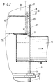
- FIG. 2 shows a detailed view of an outlet nozzle 10 and the side screens 12, the juice chamber 13 and the juice ring channel 11 arranged above it.
- the black arrow inside the outlet nozzle 10 indicates the outlet direction.
- an outlet nozzle 10 is inserted in a cutout 28 of the wall 25, an outlet nozzle 10 is inserted.
- the outlet nozzles 10 are led into the juice ring channel 11.
- the flow cross section of the juice ring channel 11 determines the speed at which the tower juice flows out of the outlet nozzle 10.
- a wall part 29 is arranged parallel to the outer wall 25 of the outer frame 1 between the bottom part 5 and a wall 30 belonging to the outlet connection arranged below it, which runs approximately parallel to the bottom part 5.
- This wall part 29 forms with the outer wall 25 of the outer frame 1 juice connection paths 22.
- the wall part 29 delimits the juice connection paths 22 inwards. These run as annular spaces, optionally interrupted by the carriers 5a, between the wall 25 of the outer frame 1 and this wall part 29 and between the bottom part 5 and the wall 30 parallel thereto.
- the upper boundary of the juice connection paths 22 is formed Outlet openings 17 of the juice spaces 13. These outlet openings 17 are preferably arranged in the base part 5.
- the outer edge of the bottom part 5, which is usually located in the outer frame 1, is provided with holes, gaps or slots.
- the tower juice flowing into the juice chamber can reach the juice connection paths 22 via these outlet openings 17. From there it flows directly into the juice ring channel 11 and from there to the outlet or outlet 10 for the tower sap. The direction of flow is marked by a black arrow.
- the juice space 13 arranged above the annularly arranged outlet openings 17 is delimited on one side by the wall 25 of the outer frame 1 and on the other side by the side screens 12.
- this juice space 13 has a greater horizontal extension than the juice connection paths 22 , so that an increase in flow velocity is achieved.
- the juice room 13 usually consists of several juice rooms 13. These juice rooms 13 are created by the design of the side screens 12 in a frame construction.
- the frame 16 of this frame construction rests with its two vertical sides on the outer wall 25 of the outer frame 1.
- the side screens 12 together with the frame 16 form segment-like structural units.
- the segments are arranged as circular segments distributed over the circumference of the outer frame 1.
- a frame 16 supports and delimits a side screen 12 in each case.
- the tower juice resulting from the extraction flows from the interior 31 of the extraction tower through the side screens 12 into a juice chamber 13 and from there through the ring-shaped outlet openings 17 and the juice connection paths 22 into the juice ring channel 11.
- the tower juice can ultimately be removed from the outlet port (s) 10 become. Guiding the tower sap in this way ensures good juice extraction without the risk of niche infections.
- the tower sap cannot therefore accumulate in niches in the extraction tower.
- the frame 16 of the side screens 12 can be removed through openings 19 in the wall 25 of the outer frame 1.
- the interior of the extraction tower can preferably be flushed or cleaned.
- the arrangement is usually made so that the individual juice spaces 13 can be cleaned in sections.
- FIG. 3 shows a detailed section of a sectional view of a second embodiment of the lower region of the outer wall 25 of an extraction tower.
- the bottom part 5 can, as in FIG. 1, be provided with bottom openings 14. If necessary, residual amounts of the solids which occur during solid-liquid extraction, for example during countercurrent extraction of beet pulp, can sink through these bottom openings 14 into a collecting vessel 15 arranged underneath.
- the collecting vessel 15 runs downwards in a bowl-shaped manner. It has an opening 21 on its one wall 32.
- a pipe 26 is inserted into this opening 21. It leads to a ring line 23 located further below.
- a locking element 33 in the pipe 26 can be used to effect or control the removal of the solid from the collecting vessel 15 via the pipe 26 and the ring line 23.
- the amount of the opening 21 in the ring line 23 flowing solids is much smaller than the flow through the side screens 12.
- the ring line 23 leads to one or more outlet ports 10, not shown. From this or these outlet ports 10, the mixture of solids and tower juice can be removed from the pipeline 26 or from the juice ring channel 11.
- a means 20 for blocking here a slide, is arranged between a drain opening 24 of the juice ring channel 11 and the ring line 23.
- the drain opening 24 can be locked or at least partially locked in the juice ring channel 11 by means of the slide 20.
- the juice ring channel 11 has a different shape in FIG. 3 than in FIG. 2. It extends over the entire circumference of the extraction tower. In Fig.2, however, it is made up of two halves. In the profile it appears triangular with a point pointing downwards. On one side it is delimited by the wall 25 of the outer frame 1. A wall 34 running obliquely to this wall 25 delimits the juice ring channel 11 on its other side. At the level of the drain opening 24, a support wall 35 is arranged horizontally, which runs parallel to the bottom part 5. As a result, there is no longer any risk of an infection niche in the tip of the triangular profile of the juice ring channel 11. Due to the substantially smooth termination of the support wall 35 with the drain opening 24 of the juice ring channel 11, the tower juice flows directly through the drain opening 24 and the slide 20 into the ring line 23 and from there into the outlet connection (s) 10, not shown.
- the slides 20 or flaps can be controlled or regulated so that one or more slides are open and others are closed. This results in a controllable deduction of solids and tower juice and thus an additional avoidance of deposits in the juice ring channel 11. Any disruptions that may occur in the extraction process can be compensated for.
- a segmental rinsing of the juice or annular space 13 or the juice spaces is made possible by pumping tower juice into the juice spaces 13 from above via lines (not shown).
- the bottom part 5 is either completely smooth or is equipped with, for example, segment-shaped sand extraction pockets 15 and is covered in this area by a bottom sieve 38.
- the segment-shaped bottom sieve 38 is let into the bottom part 5 in such a way that a scraper 4b moved over it cannot catch on a section of the bottom sieve and tear it out.
- the otherwise smooth bottom part 5 does not offer any contact surface for latching wipers 4b.
- the bottom openings 14 below the bottom sieves 38 or instead of the bottom sieves 38 can be slot-shaped, hole-shaped or even sieve-shaped. Your job is to remove the too large solids from the keep respective outlet opening 21 to prevent their clogging during occasional emptying. Instead of slots and a sieve element 38, a plurality of small sieve elements 38 embedded in the base part 5 can also be provided.
- the side screens 12 are inserted in frame 16.
- the respective frame 16 stands on the bottom part 5.
- a lower part 16a of the frame 16 does not abut the outer wall 25 of the frame 1.
- the tower juice to be extracted enters the juice ring channel 11 located below.
- the lateral, vertically extending frame parts are attached to the outer wall 25 of the outer frame 1. They are fastened there, for example screwed.
- an opening 19 is arranged in the area of a single side screen 12 for cleaning, removing and replacing the screens 12 and rinsing the juice compartment or the juice compartments 13 and the juice ring channel 11.
- the opening 19 has the size of a manhole and is also dimensioned so large that the individual side screens 12 are pushed one after the other in front of this opening 19 and can be removed through this opening 19. They can also be fixed in the extraction tower, with a separate rinsing device for cleaning.
- the part of the outer wall 25 which closes the opening 19 is preferably, with a sieve 12 and a frame 16, a structural unit which is inserted from the outside into the outer frame 1 and fastened therein. Instead of only one opening 19, two or more such openings 19 can also be or are designed as walk-in manholes.
- a removal valve can be provided. Like the previously mentioned slides 20 or flaps, this is manual or can be operated, controlled or regulated automatically.
- the control can take place mechanically, electrically or hydraulically, for example by means of so-called proportional valves, which are controlled or regulated electronically as a function of a predetermined program and / or as a function of measured values.
- the tower sap is generally continuously withdrawn. It is also possible to regulate the withdrawal quantity of the tower juice.
- two support and stiffening walls 40 or flanges encircling the outer wall 25 of the outer frame 1 are inserted into the extraction tower. They form the boundary between the outer frame 1 arranged at the top and the stand frame 6 located underneath.
- the walls 40 provide a larger contact surface of the outer wall 25 of the outer frame 1 and an outer wall 27 of the stand frame 6. In addition, they stiffen the abutting edge of the two outer walls 25, 27 of the frames 1, 6 surrounding the extraction tower.
- the walls 40 are each connected to the outer walls of the frames by welding and to one another either likewise by welding or screwing.
- the sloping wall 34 of the juice ring channel 11 is supported on the walls 40.
- Complex bottom sieve constructions with filigree bottom sieves, as in the known extraction towers, are completely eliminated in the towers according to the invention.
- the bottom part 5 is smooth and stiff in itself, essentially closed and load-bearing. The safety during operation of the scrapers 4b which slide on the base part 5 and whirl up the solids which accumulate there is enormous improved as a result.
- the bottom part 5 can be made thicker and more compact, on the other hand the wipers no longer get caught on parts of the bottom sieves that may protrude from the bottom.
- the outer frame 1 is also easier and cheaper to construct and produce, since, as in the known towers, complicated fastening devices for the bottom sieves do not have to be provided.
- the compact, smooth, stiff and stable base part 5 is only inserted into the outer frame 1 and connected to it, for example welded.
- Screen wear is relatively low due to the vertical installation of side screens 12 in frame 16 and the resulting low mechanical stress. Large solids generally cannot damage the sieves 12 because they accumulate on the bottom part 5. The relatively low strain on the side sieves 12 also ensures a stable functional sequence.
- FIG. 4 shows a schematic cross-sectional view through the juice ring channel 11 in the lower region of the outer wall 25 of the extraction tower according to FIG.
- a two-part juice ring channel 11 is shown.
- the two halves of the juice ring channel 11 abut against one another on their walls 42. From these walls 42 they taper to the respective center between two opposite walls 42.
- a vertically conical shape can also be selected. The conical shape results from the requirement to avoid niche infections. At the inaccessible narrow corners near the walls 42, there is a greater flow rate due to the smaller cross section. This forces any remaining solids there to be carried along. Then they can no longer trigger infections of the tower sap.
- flushing spouts 44 are distributed in the area of the walls 42 and on the inner circumference of the inner wall 43 provided for rinsing the juice ring channel or channels 11.
- the rinsing liquid entered above the juice spaces 13 can be removed after the rinsing process through the two outlet connections 10 arranged at a 90 ° angle to the walls 42.
- the side screens 12 are preferably arranged upright next to one another in the frame 16 distributed over the circumference of the extraction tower and are each detachably connected, for example screwed, to the outer wall of the outer frame 1 at their vertical lateral parts. Countersunk screws are preferably used which, since they do not protrude from the screen surface, cannot be sheared off by the wipers 4b.
- At least one of the side screens 12 forms a structural unit with an associated part 49 of the outer wall 25 of the outer frame 1. With the part 49, the opening 19 is closed. When opening the opening 19, the screen 12 can therefore be removed directly and does not have to be loosened and tilted in order to be removed.
- the screw connections of the adjacent side screens 12 can be reached in the frame 16 and can be detached from the inside. After loosening the screws, the individual screens 12 together with the frame 16 can be pushed to the opening 19 and removed through this.
- FIG. 5 shows in principle a perspective view of an assembly of side screen 12 and frame 16.
- the side screen 12 is non-detachably connected to the frame 16 and detachably connected to the outer wall 25 of the outer frame 1.
- a connection option for example, screwing, tacking using suitable staples, soldering or welding are conceivable.
- the screen 12 is connected to the frame 16 by welding.
- Countersunk screws 47 connect the vertical bars of the frame 16 to the outer wall 25 of the outer frame 1.
- Either a lock nut can be placed on a screw 47 from the outside, or the screw 47 pulls in one Bore with thread in the sheet metal of the outer wall 25.
- Another possibility of connecting the frame 16 to the outer wall 25 of the outer frame 1 is to weld the parts. This is indicated in FIG.
- Additional screws 46 can be provided to connect the part 49 of the outer wall 25 to the remaining wall 25.
- the screws 46 are arranged on edges 50 of the part 49 which protrude beyond the vertical beams of the frame 16.
- a screw 46 is arranged at the top and bottom in the corners of the edges 50.
- the openings 41 of the screen 12 can, as shown in the upper region of the screen 12 in Fig. 5 as a schematic diagram, be evenly distributed over the width of the screen 12. On the other hand, as shown in the lower part of the screen 12 in FIG. 5, they can also be arranged irregularly and distributed over the width of the screen 12. With the sieve openings that get bigger and bigger in the direction of rotation Solid particles, which would otherwise settle in the sieve 12, are guided or pressed by means of the scraper (s), in the direction of rotation, towards the larger opening widths and are thereby transported out.
- the shape of the sieve openings can be selected as required and can be adapted to the requirements. For example, it can be round, oval or slit-shaped. So-called slotted screens are preferably used as screens, as shown by way of example in FIG. 6.
- the frame 16 has a cross bar 16a at least on its lower side. This is narrower than the other two bars. It is only connected to the other two bars and the screen 12.
- the tower sap flows from it from the juice chamber 13 formed by the sieve 12, the vertical bars of the frame 16 and the outer wall 25 into the juice ring channel 11 underneath, which is not shown here.
- the cross bar 16a can therefore be cuboid, but also also with it be provided with an obliquely downward-pointing upper edge. This then points in the direction of flow of the tower juice to be removed.
- a round one can also be selected, for example in the case of slotted sieves in which the sieve rods are flattened round rods joined together.
- the screen openings 41 are arranged in a gap between horizontal bars 51.
- the gap width of the screen openings 41 is dimensioned differently over the screen length.
- the gap width is preferably dimensioned to the juice space 13 and increasing in the direction of rotation so that solids which are transported out with the tower juice cannot become lodged in the sieve openings 41.
- the sieve bars 51 have a double taper.
- the sieve bars 51 are attached laterally in the frame 16, which is not shown here. On the rear side, the sieve bars 51 are connected to one another by means of a bolt 52, on which they are wound, for example.
- the slotted sieves are manufactured, for example, by flattening round rods 51 wound next to one another on bolts 52.
- the mutual spacings of the sieve rods 51 are shown here apart for clarity. They are determined by the actual requirements and set by the spacings on the bolts 52. These spacings can be achieved by means of washers, spacer rings or by means of grooves provided in the bolts and can be fixed.
- the vertical frames 16 can be attached to the side surfaces of the bolts 52, for example by welding. In this case, the bolts 52 have a smaller width than the frames 16, which are not shown in FIG. 6 for reasons of clarity. They therefore do not reach as far as the outer wall 25 of the outer frame 1, as shown in FIG arrows 51b indicated.
- Such slotted screens suitable for the screens 12 are state of the art.
- the bolts 52 can also serve as a frame 16 if the juice compartment 13 does not have to be closed off from the juice compartments adjoining the side. In this case, the spacing of the sieve bars 51 from the outer wall 25, determined by the bolts 52 and spacers (not shown), is sufficient to ensure that the screened tower juice flows out of the juice chamber 13 into the juice connection path 22 underneath.
- the distance 51 a can be increased or dimensioned differently over the length of the bolt 52.
Landscapes
- Chemical & Material Sciences (AREA)
- Life Sciences & Earth Sciences (AREA)
- Biochemistry (AREA)
- Organic Chemistry (AREA)
- Chemical Kinetics & Catalysis (AREA)
- Extraction Or Liquid Replacement (AREA)
- Filtration Of Liquid (AREA)
Claims (25)
- Procédé d'extraction solide-liquide, particulièrement de saccharose hors de cossettes de betteraves, par extraction à contre-courant dans une tour d'extraction de laquelle du jus de tour est soutiré par des tamis, caractérisé en ce que du jus de tour est soutiré en même temps que les constituants solides de petite dimension résultant du procédé, tel que du sable, en substance de manière exclusive à travers des tamis latéraux (12).
- Procédé suivant la revendication 1, caractérisé en ce que des quantités résiduelles des constituants solides, qui ne se sont pas échappés par les tamis latéraux (12), sont maintenues à l'intérieur d'une partie de fond (5) dans un état capable de s'écouler.
- Procédé suivant la revendication 2, caractérisé en ce que des racleurs (4b) sont prévus à la partie de fond (5) et/ou aux tamis latéraux (12), qui maintiennent les quantités résiduelles des constituants solides dans un état capable de s'écouler.
- Procédé suivant la revendication 1, 2 ou 3, caractérisé en ce que la quantité résiduelle des constituants solides est maintenue dans un état capable de s'écouler à l'aide de jus de tour et s'échappe par un orifice de fond (14) vers un récipient collecteur (15).
- Tour d'extraction pour l'exécution du procédé pour l'extraction solide-liquide suivant l'une des revendications 1 à 4, caractérisée en ce que la partie de fond (5) est façonnée en substance de manière fermée, stable et rigide.
- Tour d'extraction suivant la revendication 5, caractérisée en ce qu'une ou plusieurs chambres à jus (13) sont disposées derrière les tamis latéraux (12).
- Tour d'extraction suivant la revendication 6, caractérisée en ce que la ou les chambres à jus (13) sont conformées derrière les tamis latéraux (12) comme une ou plusieurs chambres annulaires, les tamis latéraux (12) formant une paroi intérieure de la tour d'extraction.
- Tour d'extraction suivant la revendication 6 ou 7, caractérisée en ce que la chambre à jus ou chambre annulaire (13) ou les chambres à jus sont pourvues de passages de décharge (17), à travers lesquels le jus de tour peut être soutiré.
- Tour d'extraction suivant la revendication 8, caractérisée en ce que les passages de décharge (17) présentent des sections transversales telles que le jus de tour peut être soutiré avec une vitesse d'écoulement à peu près constante.
- Tour d'extraction suivant la revendication 8 ou 9, caractérisée en ce que les passages de décharge (17) sont disposés de manière annulaire et sont reliés à un canal de ceinture à jus (11), en vue du soutirage du jus de tour par ou à travers des chemins de communication pour jus (22) situés en-dessous de ceux-ci.
- Tour d'extraction suivant la revendication 10, caractérisée en ce que le canal de ceinture à jus (11) est relié à une canalisation circulaire (23), à travers laquelle le jus de tour peut être transféré en vue de son soutirage.
- Tour d'extraction suivant l'une des revendications 5 à 11, caractérisée en ce que les tamis latéraux (12) sont tenus chacun par un cadre (16) et sont reliés depuis l'intérieur à la paroi extérieure (25).
- Tour d'extraction suivant la revendication 12, caractérisée en ce que le cadre (16) définit la distance entre le tamis latéral (12) et la paroi extérieure (25) ainsi que la limite latérale de la chambre à jus (13) située derrière les tamis latéraux (12) et en ce qu'un ou plusieurs orifices latéraux obturables (19), qui sont conformés en trou d'homme en vue du rinçage ou du remplacement des tamis latéraux (12), sont prévus dans la paroi extérieure (25).
- Tour d'extraction suivant la revendication 13, caractérisée en ce que le tamis latéral (12), le cadre (16) et la partie associée (49) de la paroi extérieure (25) forment une unité de construction qui peut être intégrée dans la paroi extérieure (25).
- Tour d'extraction suivant l'une des revendications 6, 7 ou 8, caractérisée en ce que la chambre à jus ou chambre annulaire (13) ou les chambres à jus (13) sont associées à des moyens (20) pour bloquer ou ajuster les ouvertures de décharge (24), en vue du réglage de la vitesse d'écoulement du jus de tour s'échappant des ouvertures de décharge (24) du canal de ceinture à jus et/ou en vue du rinçage de la chambre à jus (13).
- Tour d'extraction suivant la revendication 15, caractérisée en ce que les moyens (20) pour bloquer ou ajuster les ouvertures de décharge (24) du canal de ceinture à jus (11) et/ou des chambres à jus (13) sont des vannes, clapets ou dispositifs similaires.
- Tour d'extraction suivant la revendication 16, caractérisée en ce que plusieurs vannes, clapets ou dispositifs similaires sont disposés le long du pourtour du canal de ceinture à jus (11) conformé en anneau.
- Tour d'extraction suivant la revendication 16 ou 17, caractérisée en ce que les vannes (20), clapets ou dispositifs similaires peuvent être commandés ou réglés de telle manière qu'au choix un ou plusieurs clapets sont ouverts et d'autres sont fermés, de telle sorte que la direction d'écoulement qui varie supprime largement le dépôt de solides.
- Tour d'extraction suivant la revendication 15 ou 16, caractérisée en ce que le canal de ceinture à jus (11) et/ou les chambres à jus (13) ainsi que les moyens (20) pour bloquer les ouvertures de décharge (24) sont conformés de telle sorte que le canal de ceinture à jus (11) et/ou les chambres à jus (13) peuvent être rincés par segments.
- Tour d'extraction suivant la revendication 5, caractérisée en ce que la partie de fond (5) comporte un ou plusieurs récipients collecteurs (15), poches de soutirage ou moyens semblables pour l'évacuation de la quantité résiduelle de solides produits au cours de la mise en oeuvre du procédé.
- Tour d'extraction suivant la revendication 5 ou 19, caractérisée en ce que les poches d'évacuation (15) servant à l'évacuation des solides y collectés sont disposées dans un ou plusieurs segments de la partie de fond (5).
- Tour d'extraction suivant la revendication 21, caractérisée en ce que les poches d'évacuation (15) sont pourvues d'orifices en forme de tamis (14).
- Tour d'extraction suivant la revendication 21, caractérisée en ce que les récipients collecteurs (15) sont pourvus d'orifices en forme de tamis (14).
- Tamis latéral pour une tour d'extraction suivant l'une des revendications 5 à 23, caractérisé en ce qu'il constitue, ensemble avec un cadre (16), des unités de construction en forme de segments, dans lesquelles les chemins de communication pour jus (22) sont prévus à la partie inférieure du cadre (16), entre le cadre (16) et la paroi extérieure (25).
- Tamis latéral suivant la revendication 24, caractérisé en ce que l'unité de construction (12, 16) constitue une unité ensemble avec une partie (49) pouvant être intégrée dans le châssis extérieur (1) de la paroi extérieure (25).
Priority Applications (3)
| Application Number | Priority Date | Filing Date | Title |
|---|---|---|---|
| DE59401399T DE59401399D1 (de) | 1994-04-08 | 1994-04-08 | Verfahren zur Fest-Flüssig-Extrahierung und Extraktionsturm zur Durchführung des Verfahrens |
| EP94105491A EP0678583B1 (fr) | 1994-04-08 | 1994-04-08 | Procédé d'extraction solide-liquide et tour d'extraction pour la mise en oeuvre du procédé |
| US08/416,328 US5653815A (en) | 1994-04-08 | 1995-04-04 | Process for solid-liquid extraction and extraction tower for carrying out the process |
Applications Claiming Priority (1)
| Application Number | Priority Date | Filing Date | Title |
|---|---|---|---|
| EP94105491A EP0678583B1 (fr) | 1994-04-08 | 1994-04-08 | Procédé d'extraction solide-liquide et tour d'extraction pour la mise en oeuvre du procédé |
Publications (2)
| Publication Number | Publication Date |
|---|---|
| EP0678583A1 EP0678583A1 (fr) | 1995-10-25 |
| EP0678583B1 true EP0678583B1 (fr) | 1996-12-27 |
Family
ID=8215846
Family Applications (1)
| Application Number | Title | Priority Date | Filing Date |
|---|---|---|---|
| EP94105491A Expired - Lifetime EP0678583B1 (fr) | 1994-04-08 | 1994-04-08 | Procédé d'extraction solide-liquide et tour d'extraction pour la mise en oeuvre du procédé |
Country Status (3)
| Country | Link |
|---|---|
| US (1) | US5653815A (fr) |
| EP (1) | EP0678583B1 (fr) |
| DE (1) | DE59401399D1 (fr) |
Families Citing this family (4)
| Publication number | Priority date | Publication date | Assignee | Title |
|---|---|---|---|---|
| DE19545803C2 (de) * | 1995-12-08 | 1999-07-29 | Braunschweigische Masch Bau | Verfahren zur mechanischen Entwässerung extrahierter Zuckerrübenschnitzel |
| DE102012002351A1 (de) * | 2011-11-24 | 2013-05-29 | Bma Braunschweigische Maschinenbauanstalt Ag | Diskontinuierliche Zentrifuge mit einer drehbaren Zentrifugentrommel mit einem Mantel und Verfahren zur Herstellung des Mantels |
| DE102018120565A1 (de) * | 2018-08-23 | 2020-02-27 | Bma Braunschweigische Maschinenbauanstalt Ag | Verfahren und Vorrichtung zum Aufbereiten eines Gemisches |
| CN114849280B (zh) * | 2022-06-21 | 2023-12-01 | 无锡弘鼎华化工设备有限公司 | 一种涡轮萃取塔 |
Family Cites Families (18)
| Publication number | Priority date | Publication date | Assignee | Title |
|---|---|---|---|---|
| US1570854A (en) * | 1922-09-12 | 1926-01-26 | Carl H Nordell | Means for separating, washing, and discharging comminuted solid material immersed inliquids |
| US1721858A (en) * | 1927-07-21 | 1929-07-23 | Prosco Oils Corp | Extraction |
| US2551815A (en) * | 1942-09-25 | 1951-05-08 | Helmut W Schulz | Multiple-effect centrifugation process and apparatus |
| US2726939A (en) * | 1948-04-29 | 1955-12-13 | Rose Downs & Thompson Ltd | Process for extracting solids |
| US2577135A (en) * | 1949-06-13 | 1951-12-04 | Pfeifer Und Langen | Device for extraction of sugar from sugar beet slices |
| US2637666A (en) * | 1949-07-01 | 1953-05-05 | Langen Eugen | Extraction tower for comminuted material of vegetable or plant origin, particularly sugar beets |
| US2762510A (en) * | 1952-11-21 | 1956-09-11 | Minerals & Chemicals Corp Of A | Continuous percolation system |
| US2857907A (en) * | 1957-02-07 | 1958-10-28 | Braunschweigische Maschb Ansta | Apparatus for extracting animal and vegetable substances |
| FR1210682A (fr) * | 1957-04-17 | 1960-03-10 | Braunschweigische Maschb Ansta | Dispositif pour l'extraction, le blanchiment ou le lavage de produits d'origine végétale ou animale |
| US3143395A (en) * | 1959-07-14 | 1964-08-04 | Shell Oil Co | Method of operating a fluid mixer with rotating baffles |
| DE1124922B (de) * | 1960-02-04 | 1962-03-08 | Braunschweigische Maschb Ansta | Behaelter zum Extrahieren von pflanzlichen Stoffen, insbesondere Zuckerruebenschnitzeln |
| US3629002A (en) * | 1968-12-11 | 1971-12-21 | Braunschweigische Masch Bau | Method and apparatus for extracting sugar from bagasse |
| DE2243168C3 (de) * | 1972-09-01 | 1978-07-27 | Maschinenfabrik Buckau R. Wolf Ag, 4048 Grevenbroich | Diffusionsturm zum Auslaugen, insbesondere von Zuckerrübenschnitzeln im Gegenstrom |
| DE7439969U (de) * | 1974-11-30 | 1976-07-15 | Braunschweigische Maschinenbauanstalt, 3300 Braunschweig | Extraktionsturm |
| DE7607097U1 (de) * | 1976-03-09 | 1977-06-16 | Braunschweigische Maschinenbauanstalt, 3300 Braunschweig | Extraktionsturm fuer die gegenstromauslaugung von zuckerruebenschnitzeln |
| US4115145A (en) * | 1977-07-05 | 1978-09-19 | Braunschweigische Maschinenbauanstalt | Diffusion tower for sugar beet cossettes |
| USRE31913E (en) * | 1980-10-08 | 1985-06-11 | The French Oil Mill Machinery Company | Apparatus for the continuous extraction of oils and soluble substances from solid materials |
| FR2674771B1 (fr) * | 1991-04-08 | 1995-04-21 | Robatel Slpi | Perfectionnements aux extracteurs centrifuges du type mono-etage et multi-etages. |
-
1994
- 1994-04-08 DE DE59401399T patent/DE59401399D1/de not_active Expired - Lifetime
- 1994-04-08 EP EP94105491A patent/EP0678583B1/fr not_active Expired - Lifetime
-
1995
- 1995-04-04 US US08/416,328 patent/US5653815A/en not_active Expired - Lifetime
Also Published As
| Publication number | Publication date |
|---|---|
| US5653815A (en) | 1997-08-05 |
| DE59401399D1 (de) | 1997-02-06 |
| EP0678583A1 (fr) | 1995-10-25 |
Similar Documents
| Publication | Publication Date | Title |
|---|---|---|
| DE2930581A1 (de) | Zentrifuge zum sortieren und trennen von feststoffen | |
| DE19524276C2 (de) | Vorrichtung zum Entfernen von Abscheidegut aus in einem Gerinne strömender Flüssigkeit | |
| WO1993000489A1 (fr) | Dessableur long pour la separation et l'evacuation de sable de canaux d'amenee, notamment de stations d'epuration | |
| DE19648875A1 (de) | Vorrichtung zur Behandlung von pump- und oder rührfähigen Massen, insbesondere Fermenter vorzugsweise für Biomasse | |
| EP2562477B1 (fr) | Dispositif de décrassage destiné à la sortie de résidus de combustion d'une installation de combustion | |
| DE3941916C2 (fr) | ||
| EP0678583B1 (fr) | Procédé d'extraction solide-liquide et tour d'extraction pour la mise en oeuvre du procédé | |
| DE2320859A1 (de) | Verfahren und einrichtung zur herbeifuehrung von partikelwachstum in einer stroemenden fluessigkeitssuspension | |
| DE4412124C2 (de) | Vorrichtung zum Entfernen von Abscheidegut aus in einem Gerinne strömender Flüssigkeit | |
| DE19900280A1 (de) | Fluid-Trennvorrichtung | |
| DE4314673C1 (de) | Vorrichtung zum Entfernen von Abscheidegut aus einer Flüssigkeit | |
| DE102007035081A1 (de) | Siebrechenvorrichtung sowie Verwendungen davon | |
| DE1632285A1 (de) | Vielfachkammerzentrifuge | |
| DE2532528A1 (de) | Verfahren zur einstellung eines vorbestimmten verteilungsgesetzes des durchflusses in einem stroemenden mediumsstrom sowie vorrichtung zur durchfuehrung des verfahrens | |
| DE20201367U1 (de) | Vorrichtung zum Separieren und Austragen von Spänen und Arbeitsflüssigkeit | |
| DE69721191T2 (de) | Horizontale Zentrifuge für die Ölextraktion aus ölhältigen Gemischen | |
| EP0056611B1 (fr) | Réservoir couché, en particulier pour le traitement de moût de raisins | |
| EP0594167A1 (fr) | Dispositif pour extraire des matériaux séparables d'un liquide coulant dans une rigole | |
| AT407492B (de) | Filtervorrichtung für ein fliessfähiges medium, insbesondere eine schmelze | |
| EP3626042B1 (fr) | Dispositif de séparation et de distribution combiné pour lisiers, résidus de fermentation et analogues | |
| DE3200714C2 (de) | Liegender Weinmaische-Behälter | |
| DE3035228A1 (de) | Vorrichtung zum estrahieren von loeslichen bestandteilen aus feststoffen | |
| WO1998024530A1 (fr) | Bassin de decantation de forme rectangulaire pour la separation de la boue contenue dans des eaux usees | |
| DE3941900C2 (fr) | ||
| DE1227842B (de) | Schneckensiebzentrifuge |
Legal Events
| Date | Code | Title | Description |
|---|---|---|---|
| PUAI | Public reference made under article 153(3) epc to a published international application that has entered the european phase |
Free format text: ORIGINAL CODE: 0009012 |
|
| 17P | Request for examination filed |
Effective date: 19941010 |
|
| AK | Designated contracting states |
Kind code of ref document: A1 Designated state(s): BE DE FR GB IT |
|
| GRAG | Despatch of communication of intention to grant |
Free format text: ORIGINAL CODE: EPIDOS AGRA |
|
| 17Q | First examination report despatched |
Effective date: 19960216 |
|
| GRAH | Despatch of communication of intention to grant a patent |
Free format text: ORIGINAL CODE: EPIDOS IGRA |
|
| GRAH | Despatch of communication of intention to grant a patent |
Free format text: ORIGINAL CODE: EPIDOS IGRA |
|
| GRAH | Despatch of communication of intention to grant a patent |
Free format text: ORIGINAL CODE: EPIDOS IGRA |
|
| GRAH | Despatch of communication of intention to grant a patent |
Free format text: ORIGINAL CODE: EPIDOS IGRA |
|
| GRAA | (expected) grant |
Free format text: ORIGINAL CODE: 0009210 |
|
| AK | Designated contracting states |
Kind code of ref document: B1 Designated state(s): BE DE FR GB IT |
|
| REF | Corresponds to: |
Ref document number: 59401399 Country of ref document: DE Date of ref document: 19970206 |
|
| ET | Fr: translation filed | ||
| GBT | Gb: translation of ep patent filed (gb section 77(6)(a)/1977) |
Effective date: 19970125 |
|
| ITF | It: translation for a ep patent filed | ||
| PLBE | No opposition filed within time limit |
Free format text: ORIGINAL CODE: 0009261 |
|
| STAA | Information on the status of an ep patent application or granted ep patent |
Free format text: STATUS: NO OPPOSITION FILED WITHIN TIME LIMIT |
|
| 26N | No opposition filed | ||
| REG | Reference to a national code |
Ref country code: GB Ref legal event code: IF02 |
|
| PGFP | Annual fee paid to national office [announced via postgrant information from national office to epo] |
Ref country code: BE Payment date: 20120430 Year of fee payment: 19 |
|
| PGFP | Annual fee paid to national office [announced via postgrant information from national office to epo] |
Ref country code: GB Payment date: 20120425 Year of fee payment: 19 |
|
| PGFP | Annual fee paid to national office [announced via postgrant information from national office to epo] |
Ref country code: IT Payment date: 20120421 Year of fee payment: 19 |
|
| PGFP | Annual fee paid to national office [announced via postgrant information from national office to epo] |
Ref country code: DE Payment date: 20130423 Year of fee payment: 20 |
|
| PGFP | Annual fee paid to national office [announced via postgrant information from national office to epo] |
Ref country code: FR Payment date: 20130523 Year of fee payment: 20 |
|
| BERE | Be: lapsed |
Owner name: *BRAUNSCHWEIGISCHE MASCHINENBAUANSTALT A.G. Effective date: 20130430 |
|
| GBPC | Gb: european patent ceased through non-payment of renewal fee |
Effective date: 20130408 |
|
| PG25 | Lapsed in a contracting state [announced via postgrant information from national office to epo] |
Ref country code: GB Free format text: LAPSE BECAUSE OF NON-PAYMENT OF DUE FEES Effective date: 20130408 Ref country code: BE Free format text: LAPSE BECAUSE OF NON-PAYMENT OF DUE FEES Effective date: 20130430 |
|
| PG25 | Lapsed in a contracting state [announced via postgrant information from national office to epo] |
Ref country code: IT Free format text: LAPSE BECAUSE OF NON-PAYMENT OF DUE FEES Effective date: 20130408 |
|
| REG | Reference to a national code |
Ref country code: DE Ref legal event code: R071 Ref document number: 59401399 Country of ref document: DE |
|
| PG25 | Lapsed in a contracting state [announced via postgrant information from national office to epo] |
Ref country code: DE Free format text: LAPSE BECAUSE OF EXPIRATION OF PROTECTION Effective date: 20140409 |
|
| P01 | Opt-out of the competence of the unified patent court (upc) registered |
Effective date: 20230526 |