EP0677159B1 - Mehrschichtrohr und extruderdüse für seine herstellung - Google Patents
Mehrschichtrohr und extruderdüse für seine herstellung Download PDFInfo
- Publication number
- EP0677159B1 EP0677159B1 EP94903923A EP94903923A EP0677159B1 EP 0677159 B1 EP0677159 B1 EP 0677159B1 EP 94903923 A EP94903923 A EP 94903923A EP 94903923 A EP94903923 A EP 94903923A EP 0677159 B1 EP0677159 B1 EP 0677159B1
- Authority
- EP
- European Patent Office
- Prior art keywords
- sleeve
- reinforcement member
- ply
- die
- lacunary
- Prior art date
- Legal status (The legal status is an assumption and is not a legal conclusion. Google has not performed a legal analysis and makes no representation as to the accuracy of the status listed.)
- Expired - Lifetime
Links
Images


Classifications
-
- F—MECHANICAL ENGINEERING; LIGHTING; HEATING; WEAPONS; BLASTING
- F16—ENGINEERING ELEMENTS AND UNITS; GENERAL MEASURES FOR PRODUCING AND MAINTAINING EFFECTIVE FUNCTIONING OF MACHINES OR INSTALLATIONS; THERMAL INSULATION IN GENERAL
- F16L—PIPES; JOINTS OR FITTINGS FOR PIPES; SUPPORTS FOR PIPES, CABLES OR PROTECTIVE TUBING; MEANS FOR THERMAL INSULATION IN GENERAL
- F16L11/00—Hoses, i.e. flexible pipes
- F16L11/04—Hoses, i.e. flexible pipes made of rubber or flexible plastics
- F16L11/08—Hoses, i.e. flexible pipes made of rubber or flexible plastics with reinforcements embedded in the wall
- F16L11/081—Hoses, i.e. flexible pipes made of rubber or flexible plastics with reinforcements embedded in the wall comprising one or more layers of a helically wound cord or wire
- F16L11/082—Hoses, i.e. flexible pipes made of rubber or flexible plastics with reinforcements embedded in the wall comprising one or more layers of a helically wound cord or wire two layers
-
- B—PERFORMING OPERATIONS; TRANSPORTING
- B29—WORKING OF PLASTICS; WORKING OF SUBSTANCES IN A PLASTIC STATE IN GENERAL
- B29C—SHAPING OR JOINING OF PLASTICS; SHAPING OF MATERIAL IN A PLASTIC STATE, NOT OTHERWISE PROVIDED FOR; AFTER-TREATMENT OF THE SHAPED PRODUCTS, e.g. REPAIRING
- B29C48/00—Extrusion moulding, i.e. expressing the moulding material through a die or nozzle which imparts the desired form; Apparatus therefor
- B29C48/03—Extrusion moulding, i.e. expressing the moulding material through a die or nozzle which imparts the desired form; Apparatus therefor characterised by the shape of the extruded material at extrusion
- B29C48/09—Articles with cross-sections having partially or fully enclosed cavities, e.g. pipes or channels
-
- B—PERFORMING OPERATIONS; TRANSPORTING
- B29—WORKING OF PLASTICS; WORKING OF SUBSTANCES IN A PLASTIC STATE IN GENERAL
- B29C—SHAPING OR JOINING OF PLASTICS; SHAPING OF MATERIAL IN A PLASTIC STATE, NOT OTHERWISE PROVIDED FOR; AFTER-TREATMENT OF THE SHAPED PRODUCTS, e.g. REPAIRING
- B29C48/00—Extrusion moulding, i.e. expressing the moulding material through a die or nozzle which imparts the desired form; Apparatus therefor
- B29C48/25—Component parts, details or accessories; Auxiliary operations
- B29C48/255—Flow control means, e.g. valves
- B29C48/2556—Flow control means, e.g. valves provided in or in the proximity of dies
-
- B—PERFORMING OPERATIONS; TRANSPORTING
- B29—WORKING OF PLASTICS; WORKING OF SUBSTANCES IN A PLASTIC STATE IN GENERAL
- B29C—SHAPING OR JOINING OF PLASTICS; SHAPING OF MATERIAL IN A PLASTIC STATE, NOT OTHERWISE PROVIDED FOR; AFTER-TREATMENT OF THE SHAPED PRODUCTS, e.g. REPAIRING
- B29C48/00—Extrusion moulding, i.e. expressing the moulding material through a die or nozzle which imparts the desired form; Apparatus therefor
- B29C48/25—Component parts, details or accessories; Auxiliary operations
- B29C48/30—Extrusion nozzles or dies
- B29C48/32—Extrusion nozzles or dies with annular openings, e.g. for forming tubular articles
- B29C48/325—Extrusion nozzles or dies with annular openings, e.g. for forming tubular articles being adjustable, i.e. having adjustable exit sections
-
- B—PERFORMING OPERATIONS; TRANSPORTING
- B29—WORKING OF PLASTICS; WORKING OF SUBSTANCES IN A PLASTIC STATE IN GENERAL
- B29C—SHAPING OR JOINING OF PLASTICS; SHAPING OF MATERIAL IN A PLASTIC STATE, NOT OTHERWISE PROVIDED FOR; AFTER-TREATMENT OF THE SHAPED PRODUCTS, e.g. REPAIRING
- B29C48/00—Extrusion moulding, i.e. expressing the moulding material through a die or nozzle which imparts the desired form; Apparatus therefor
- B29C48/25—Component parts, details or accessories; Auxiliary operations
- B29C48/30—Extrusion nozzles or dies
- B29C48/32—Extrusion nozzles or dies with annular openings, e.g. for forming tubular articles
- B29C48/335—Multiple annular extrusion nozzles in coaxial arrangement, e.g. for making multi-layered tubular articles
- B29C48/337—Multiple annular extrusion nozzles in coaxial arrangement, e.g. for making multi-layered tubular articles the components merging at a common location
- B29C48/338—Multiple annular extrusion nozzles in coaxial arrangement, e.g. for making multi-layered tubular articles the components merging at a common location using a die with concentric parts, e.g. rings, cylinders
-
- B—PERFORMING OPERATIONS; TRANSPORTING
- B32—LAYERED PRODUCTS
- B32B—LAYERED PRODUCTS, i.e. PRODUCTS BUILT-UP OF STRATA OF FLAT OR NON-FLAT, e.g. CELLULAR OR HONEYCOMB, FORM
- B32B1/00—Layered products having a non-planar shape
- B32B1/08—Tubular products
-
- B—PERFORMING OPERATIONS; TRANSPORTING
- B32—LAYERED PRODUCTS
- B32B—LAYERED PRODUCTS, i.e. PRODUCTS BUILT-UP OF STRATA OF FLAT OR NON-FLAT, e.g. CELLULAR OR HONEYCOMB, FORM
- B32B27/00—Layered products comprising a layer of synthetic resin
- B32B27/12—Layered products comprising a layer of synthetic resin next to a fibrous or filamentary layer
-
- B—PERFORMING OPERATIONS; TRANSPORTING
- B32—LAYERED PRODUCTS
- B32B—LAYERED PRODUCTS, i.e. PRODUCTS BUILT-UP OF STRATA OF FLAT OR NON-FLAT, e.g. CELLULAR OR HONEYCOMB, FORM
- B32B27/00—Layered products comprising a layer of synthetic resin
- B32B27/32—Layered products comprising a layer of synthetic resin comprising polyolefins
-
- B—PERFORMING OPERATIONS; TRANSPORTING
- B32—LAYERED PRODUCTS
- B32B—LAYERED PRODUCTS, i.e. PRODUCTS BUILT-UP OF STRATA OF FLAT OR NON-FLAT, e.g. CELLULAR OR HONEYCOMB, FORM
- B32B5/00—Layered products characterised by the non- homogeneity or physical structure, i.e. comprising a fibrous, filamentary, particulate or foam layer; Layered products characterised by having a layer differing constitutionally or physically in different parts
- B32B5/02—Layered products characterised by the non- homogeneity or physical structure, i.e. comprising a fibrous, filamentary, particulate or foam layer; Layered products characterised by having a layer differing constitutionally or physically in different parts characterised by structural features of a fibrous or filamentary layer
- B32B5/028—Net structure, e.g. spaced apart filaments bonded at the crossing points
-
- F—MECHANICAL ENGINEERING; LIGHTING; HEATING; WEAPONS; BLASTING
- F16—ENGINEERING ELEMENTS AND UNITS; GENERAL MEASURES FOR PRODUCING AND MAINTAINING EFFECTIVE FUNCTIONING OF MACHINES OR INSTALLATIONS; THERMAL INSULATION IN GENERAL
- F16L—PIPES; JOINTS OR FITTINGS FOR PIPES; SUPPORTS FOR PIPES, CABLES OR PROTECTIVE TUBING; MEANS FOR THERMAL INSULATION IN GENERAL
- F16L11/00—Hoses, i.e. flexible pipes
- F16L11/04—Hoses, i.e. flexible pipes made of rubber or flexible plastics
- F16L11/08—Hoses, i.e. flexible pipes made of rubber or flexible plastics with reinforcements embedded in the wall
- F16L11/085—Hoses, i.e. flexible pipes made of rubber or flexible plastics with reinforcements embedded in the wall comprising one or more braided layers
-
- B—PERFORMING OPERATIONS; TRANSPORTING
- B29—WORKING OF PLASTICS; WORKING OF SUBSTANCES IN A PLASTIC STATE IN GENERAL
- B29C—SHAPING OR JOINING OF PLASTICS; SHAPING OF MATERIAL IN A PLASTIC STATE, NOT OTHERWISE PROVIDED FOR; AFTER-TREATMENT OF THE SHAPED PRODUCTS, e.g. REPAIRING
- B29C48/00—Extrusion moulding, i.e. expressing the moulding material through a die or nozzle which imparts the desired form; Apparatus therefor
- B29C48/001—Combinations of extrusion moulding with other shaping operations
- B29C48/002—Combinations of extrusion moulding with other shaping operations combined with surface shaping
-
- B—PERFORMING OPERATIONS; TRANSPORTING
- B29—WORKING OF PLASTICS; WORKING OF SUBSTANCES IN A PLASTIC STATE IN GENERAL
- B29C—SHAPING OR JOINING OF PLASTICS; SHAPING OF MATERIAL IN A PLASTIC STATE, NOT OTHERWISE PROVIDED FOR; AFTER-TREATMENT OF THE SHAPED PRODUCTS, e.g. REPAIRING
- B29C48/00—Extrusion moulding, i.e. expressing the moulding material through a die or nozzle which imparts the desired form; Apparatus therefor
- B29C48/16—Articles comprising two or more components, e.g. co-extruded layers
- B29C48/18—Articles comprising two or more components, e.g. co-extruded layers the components being layers
- B29C48/21—Articles comprising two or more components, e.g. co-extruded layers the components being layers the layers being joined at their surfaces
-
- B—PERFORMING OPERATIONS; TRANSPORTING
- B29—WORKING OF PLASTICS; WORKING OF SUBSTANCES IN A PLASTIC STATE IN GENERAL
- B29D—PRODUCING PARTICULAR ARTICLES FROM PLASTICS OR FROM SUBSTANCES IN A PLASTIC STATE
- B29D23/00—Producing tubular articles
- B29D23/001—Pipes; Pipe joints
-
- B—PERFORMING OPERATIONS; TRANSPORTING
- B32—LAYERED PRODUCTS
- B32B—LAYERED PRODUCTS, i.e. PRODUCTS BUILT-UP OF STRATA OF FLAT OR NON-FLAT, e.g. CELLULAR OR HONEYCOMB, FORM
- B32B2250/00—Layers arrangement
- B32B2250/40—Symmetrical or sandwich layers, e.g. ABA, ABCBA, ABCCBA
-
- B—PERFORMING OPERATIONS; TRANSPORTING
- B32—LAYERED PRODUCTS
- B32B—LAYERED PRODUCTS, i.e. PRODUCTS BUILT-UP OF STRATA OF FLAT OR NON-FLAT, e.g. CELLULAR OR HONEYCOMB, FORM
- B32B2262/00—Composition or structural features of fibres which form a fibrous or filamentary layer or are present as additives
- B32B2262/02—Synthetic macromolecular fibres
- B32B2262/0253—Polyolefin fibres
-
- B—PERFORMING OPERATIONS; TRANSPORTING
- B32—LAYERED PRODUCTS
- B32B—LAYERED PRODUCTS, i.e. PRODUCTS BUILT-UP OF STRATA OF FLAT OR NON-FLAT, e.g. CELLULAR OR HONEYCOMB, FORM
- B32B2307/00—Properties of the layers or laminate
- B32B2307/50—Properties of the layers or laminate having particular mechanical properties
- B32B2307/54—Yield strength; Tensile strength
-
- B—PERFORMING OPERATIONS; TRANSPORTING
- B32—LAYERED PRODUCTS
- B32B—LAYERED PRODUCTS, i.e. PRODUCTS BUILT-UP OF STRATA OF FLAT OR NON-FLAT, e.g. CELLULAR OR HONEYCOMB, FORM
- B32B2307/00—Properties of the layers or laminate
- B32B2307/70—Other properties
- B32B2307/726—Permeability to liquids, absorption
- B32B2307/7265—Non-permeable
-
- B—PERFORMING OPERATIONS; TRANSPORTING
- B32—LAYERED PRODUCTS
- B32B—LAYERED PRODUCTS, i.e. PRODUCTS BUILT-UP OF STRATA OF FLAT OR NON-FLAT, e.g. CELLULAR OR HONEYCOMB, FORM
- B32B2571/00—Protective equipment
-
- B—PERFORMING OPERATIONS; TRANSPORTING
- B32—LAYERED PRODUCTS
- B32B—LAYERED PRODUCTS, i.e. PRODUCTS BUILT-UP OF STRATA OF FLAT OR NON-FLAT, e.g. CELLULAR OR HONEYCOMB, FORM
- B32B2597/00—Tubular articles, e.g. hoses, pipes
Definitions
- the invention relates to the technical field of conduits used for the transport of gases, fluids, such as water, rainwater, wastewater, but also as a protective sheath, of conductors or various networks. It relates more particularly to conduits having a diameter between 30 and 1000 mm.
- conduits of this type are made of cast iron, steel, cement, or very thick synthetic material, to have the desired resistance. All these conduits have either the disadvantage of having a high weight per linear meter, or, when they are made of polyvinyl chloride, of being polluting for the environment, since they contain chlorine.
- Multilayer conduits are also known which, made of composite materials, that is to say from materials of different nature, have the drawback of requiring complex, expensive and difficult-to-adjust tools for their manufacture.
- the present invention aims to remedy these drawbacks by providing a waterproof and resistant multilayer pipe, having a low weight per linear meter and which can be produced in non-polluting materials, incorporating or not, recovery products.
- the reinforcing reinforcement has, over all or part of its length, a lacunar structure which is crosslinked, of which only the faces, respectively internal and external, are linked to the adjacent layers, and whose gaps are closed but not filled by these layers.
- This duct has the particularity of having a central lacunar reinforcement, forming a spacer between the adjacent plies and on which these plies are fixed to form a perfectly waterproof, light and resistant tubular body.
- the frame and its layers are made of the same synthetic material or of synthetic materials of different natures or colors, obtained from virgin granules or mixed with recycling products.
- the plastic reinforcement with a incomplete structure is replaced locally by a uniform layer of material which can be used to form a connecting tulip for two sections of conduits.
- the invention also relates to the die for the manufacture of such a multilayer pipe.
- Such a die makes it possible to continuously produce the frame with a incomplete structure and the two adjacent plies, respectively interior and exterior, sandwiching this frame and coming to be pressed and bonded to it during cooling.
- the three material supply channels can be connected to the same extruder or to three different extruders. This independence also makes it possible to supply only two of the supply channels, for example, the first and the second supply channel or the second and the third channel to form a conduit comprising only an inner ply or a outer layer associated with the frame.
- the reference 2 designates a frame with a sparse structure made of synthetic material and comprising, in known manner, a mesh structure delimited by longitudinal wires or cords 3 and circular rings 4, linked to the first at regular intervals.
- the reference 5 designates an inner ply of synthetic material
- the reference 6 designates an outer ply, also made of synthetic material.
- inner ply and outer ply designate the plies delimiting the wall of the duct and which, depending on the embodiments, may or may not be adjacent to the central lacunar reinforcement, where at one of the gaps in the duct.
- the material constituting the frame 2 and the material constituting the plies 5 and 6 may be identical or be different by their nature, their color, or by any other characteristic.
- one of the three aforementioned layers can be produced in recovered materials.
- the three layers are produced in polyolefins and for example, in polyethylene, recovered or not.
- this duct Because of its structure, and in particular thanks to the frame 2 sandwiched between the two plies 5 and 6, of small thickness and to which the first is linked, this duct has very good rigidity.
- the composite duct thus obtained is much lighter than the traditional ducts of cast iron, cement or in extruded synthetic material.
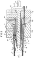
- This duct is manufactured continuously by means of a die, an embodiment of which is shown in FIG. 3.
- the references 10 and 11 designating die body elements and 12 the die nose. These elements are linked together and fixed to the frame of an extrusion installation, not shown.
- this die comprises a first extrusion assembly A forming the interior ply 5, a second extrusion assembly B forming the frame 2 with a sparse structure, and a third extrusion assembly C forming the exterior ply 6 .
- the first extrusion assembly A is composed of an axial core 13 and a central ring 14 surrounding it.
- the core 13 is fixed to the body 10 by its upstream end. It defines, with the internal bore of the ring 14, an annular channel 15 which extends over its entire length and is connected, upstream, to a first material supply channel 16.
- the annular channel 15 opens out, in downstream, near the convergent 17a of a refrigerated shaper 17, fixed in the extension of the die to cool and shape the tubular sheet 5 when leaving.
- the second extrusion assembly B is constituted by the aforementioned central ring 14, by an intermediate ring 18 surrounding it and integral with the body 11, and by a ring 19 for forming gaps, slidably mounted on the outside of the intermediate ring 18.
- the rings 14 and 18 delimit between them a second annular channel 20 communicating upstream, with a second supply channel 22 and opening, downstream, through an annular slot 23.
- this annular slot is formed between a collar 14a of the ring 14 and the chamfered end downstream of the intermediate ring 18. It opens radially outwards.
- the ring 19 has at its free end notches 24. It is connected, by a linkage 25 passing through the bodies 10 and 11, to a control plate 26, disposed outside the die and itself connected to motor means capable of move it longitudinally and alternately in both directions, as shown by arrow 27.
- This continuous layer of material which locally replaces the lacunar layer, reinforces the conduit in the areas where it must undergo a tuliping, that is to say be radially deformed to present a tulip promoting the connection by interlocking of two conduits.
- the third extrusion assembly C is composed of an outer ring 30, integral with the nose 12 of the die and delimiting, by its outer face and with a bore, formed in this nose, a third annular channel 33.
- This channel is connected to an upstream supply chamber 35, itself connected to a third material supply channel 36.
- the downstream end of the annular channel 33 opens in the direction of the shaper 17 and thus allows the outer ply 6 to come to rest on the frame 2, itself bearing on the inner ply 5, which circulates on the shaper.
- Figure 3 shows that the inner bore of the outer sleeve 30 is clearly at a radial distance from the closure sleeve 19, so as not to hinder the movements of the latter.
- the feed channels 16-22 and 36 can be connected to the same extruder or to several extruders, which makes it possible to produce, from this die, conduits having layers of synthetic material of the same kind, or of different natures. , and this according to the needs and constraints specific to the use of this conduit.
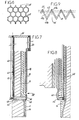
- the lacunar structure forming the reinforcement 2 may have meshes different from those shown in FIG. 1 and, for example, staggered square meshes, lozenge meshes or honeycomb meshes, as shown in FIGS. 4, 5 and 6.
- the staggered square meshes are obtained by a variant of the device of FIG. 3, comprising means, not shown, for pivoting the plate 26, the linkage 25 and the ring 19 around the longitudinal axis of the die.
- This rotation the angular amplitude of which has a value substantially equal to half the width of a mesh, takes place in one direction or the other while the ring 19 is in the upstream position for releasing the slot.
- annular 23 It is obvious that under these conditions, the rods 25, pass through the bodies 10 and 11 of the die by lights, in an arc of a circle or the like, leaving them the clearance necessary for this rotation.
- Figures 7 and 8 show alternative embodiments of the die of Figure 3, variants for producing lozenge or honeycomb meshes.
- the ring 19 for forming the gaps is associated with a ring 40 which, arranged downstream of it, is linked to the means 25 to 27 moving this bush.
- this connection is ensured by an axial rod 42, linked to the plate 26 and mounted free in translation in a bore 41 of the core 13, and by radial arms 43 arranged with clearance in radial slots 44 and 45, respectively of the core 13 and of the ring 14.
- the arms 43 which intersect the annular slot 15 and consequently the trajectory of the material constituting the layer 5, have, in cross section, a lamellar profile with an acute edge to minimize their action on the flowing material.
- the annular slot 15 includes a compression zone allowing the material to absorb the slots produced by the arms and to reform a regular ring.
- the ring 40 is linked to the plate 26 ( Figure 3), by tie rods 43 mounted sliding vertically in the ring 14 and linked to an internal collar 44 of this ring.
- the facing edges respectively of the ring 19 and of the ring 40 are provided with overlapping teeth, respectively 45 and 46, and formed of triangular teeth, separated by "V” notches, and delimiting between them a serrated slot 47.
- the ring 19 and the ring 40 are simultaneously driven in a longitudinal displacement movement, alternately, downstream and then upstream, so as to move the slot serrated 47 formed between the two teeth between a downstream position, shown in FIG. 9, in which what may be called the apex 47a of the teeth of the serrated slot 47 is at the level of the annular slot 23 and an upstream position in which these are the hollow 47b which are at the level of this slot.
- the material exiting through the annular slot 23 is distributed over the branches 47c between vertices and hollows and also forms the lozenge mesh, shown in FIG. 5.
- honeycomb meshes shown in FIG. 6 are obtained by one or other of the dies in FIGS. 7 and 8, by temporarily stopping the longitudinal movement of the rings 19 and 40, at each of their ends. race to form, as shown in FIG. 6, bars 48, connecting the strands 49 formed by the branches 47c of the serrated slot 47.
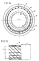
- FIGS. 10 and 11, and 13 and 14 show two other embodiments of the second extrusion assembly B making it possible to obtain lacunar structures with lozenge meshes.
- the assembly B is composed of two coaxial rings 50, 51 delimiting between them the second annular channel 20.
- the annular extrusion slot 52 is delimited between two divergent frustoconical bearing surfaces formed on extreme and downstream collars 53 and 54, respectively, of the ring 50 and of the ring 51.
- In each of the conical surfaces open radial notches 55 and 56 (FIG. 11) angularly spaced with the same angular pitch.
- Each of the two rings 50 and 51 is connected to means not shown, but known to those skilled in the art, capable of rotating it in the opposite direction to the other ring, and for example and as shown in FIG. 11, in the direction of arrow 57 for the ring 50 and in that of arrow 58 for the ring 51.
- each notch 55 and 56 is successively partially obscured by the conical bearing face to face, as shown in solid lines in Figure 11, or supplemented by the notch facing, as shown in phantom in the same figure.
- the notches When the notches are partially obscured, they form the inclined strands of the diamond-shaped meshes of the lacunar structure shown in FIG. 12 and when they are in coincidence with the notches facing each other, they form the crossing points of the meshes.
- the extrusion assembly B is composed of an outer ring 60 and an inner ring 61 coaxial with the previous one and delimiting, with it, the second annular channel 20.
- the annular extrusion slot 62 is formed between the downstream end of the internal bore 63 of the ring 60 and the periphery of an annular knife 64.
- the knife has an external diameter smaller than that of the internal bore 63 and is mounted on the end of a tubular support 65 with an eccentricity of its longitudinal axis relative to that of this support.
- This support is arranged inside the ring 61, between this ring and that 14, of the first extrusion assembly A. By its upstream part, the support is connected to means, not shown, capable of driving it in rotation around the ring 14.
- the outer ring 60 has, at the downstream end of its internal bore, longitudinal and blind notches 66, opening into this bore and from the end of the ring (FIG. 14). These notches are spaced by a constant angular step.
- the annular knife 64 is coaxial with its tubular support 65 which is then mounted free in rotation on a bearing surface of the ring 14, this bearing being itself eccentric relative to the longitudinal axis of this ring.
- the support is mounted with radial clearance between the rings 14 and 61 and is connected to means capable of imparting nutation to it, that is to say a substantially pendular movement displacing the periphery of the knife against the bore 63 of the outer ring 60.
- Figure 16 shows an embodiment of a five-layer multilayer pipe.
- This conduit comprises between the reinforcing reinforcement 2, linked to the outer ply 6, and the inner ply 5, an intermediate ply 5a and a second reinforcing reinforcement 2a.
- the intermediate ply 5a is linked by fusion to the second reinforcing reinforcement 2a which is itself linked by fusion to the internal ply 5.
- the meshes of the two reinforcing reinforcements 5 and 5a with a lacunar structure are offset, transversely and longitudinally, so that the crossing points of one reinforcement are between the meshes of the other reinforcement and this in order to on the one hand, to distribute the heat concentration zones at the outlet of the die and, on the other hand, to improve the resistance of the complex obtained.
- FIG. 17 shows a three-layer duct obtained by sectioning the product coming out of any of the dies described above in section and shaped to allow its connection by fitting with an identical duct.
- This conduit comprises, at one from its ends, a fitting end piece 70 and, at its other end, a housing 71 for receiving this end piece.
- the end piece 70 has an outside diameter smaller than that outside of the duct, while the housing 71 has an inside diameter greater than the inside diameter of this same duct and equal, with the functional clearance close to that outside the end piece.
- This nozzle 70 is obtained by bringing the corresponding end of the conduit to a temperature at least equal to the softening temperature of the materials making up its layers and by engaging it in the assembly shown in FIG. 18 and composed of an axial punch 72 and jaws 73.
- the punch 72 has an internal diameter equal to that of the conduit.
- the jaws 73 are movable radially, in the direction of the arrow 74, between a position in which they tolerate the engagement of the end of the conduit and a position of end of compression. When tightened on the end of the conduit, they crush the strands making up the reinforcement 2 by laminating them between the plies 5 and 6, which also undergo at least partial rolling.
- This compression-rolling is strong enough to form, if necessary and by means of dies 75 formed in the jaws, one or more tenons 76 projecting radially from the nozzle.
- the nozzle is composed of a reinforced wall, generally full.
- the preparation of the housing 71 is carried out under the same conditions but by means of the assembly shown in FIG. 19, and comprising an external crown 77 and an internal punch 78.
- the end of the conduit is engaged in the crown 77, which ensures its external calibration, as the punch 72 ensures the internal calibration of the end piece 70. It is deformed radially by the introduction into its internal bore of the punch 78, having an external diameter larger than the internal diameter of the conduit and equal to that internal to the housing 71 This radial force also causes compression and rolling of the strands of the reinforcing reinforcement 2 between the plies 5 and 6.
- the housing 71 When the housing 71 is provided with longitudinal grooves 79, with locking notch 80 for the tenons 76, these grooves and notches are formed by indentations 81, movable radially in the punch 78 and connected to means capable of moving them between a position erasure in the mandrel and a working position, in which they project from this mandrel and locally deform the reinforced wall produced at this end.
- the reinforcing reinforcement 2 makes it possible to conform the ends of the duct by applying pressures which can be obtained by simple, reliable and inexpensive mechanical means, and to obtain, in the areas fitting not requiring deformability, rigid and resistant walls promoting the connection of conduits.
- the grooves 79 are helical. This arrangement makes it possible, by communicating a longitudinal thrust, for example by means of the bucket of a backhoe, on the free end of a conduit, to communicate at its other end the movements of translation and rotation favoring the locking of tenons 76 in the notches 80. This arrangement is particularly advantageous for conduits having a diameter greater than 400 mm and difficult to grasp by a single man.
- the conduit according to the invention can be used to transport gases, fluids, sounds, but also to constitute a protective sheath for conductors or various networks.
- a resistance equal to that of current conduits made of various materials it has a greater lightness which makes it possible to envisage its application from very small diameters of the order of 30 mm up to diameters of on the order of 1000 mm which, until now, could not have been envisaged in sections of current length, because of their weight.
Landscapes
- Engineering & Computer Science (AREA)
- Mechanical Engineering (AREA)
- General Engineering & Computer Science (AREA)
- Manufacturing & Machinery (AREA)
- Extrusion Moulding Of Plastics Or The Like (AREA)
- Moulds For Moulding Plastics Or The Like (AREA)
- Rigid Pipes And Flexible Pipes (AREA)
- Blow-Moulding Or Thermoforming Of Plastics Or The Like (AREA)
- Nozzles (AREA)
- Moulding By Coating Moulds (AREA)
- Treatment Of Water By Ion Exchange (AREA)
Claims (15)
- Mehrschicht-Rohr, umfassend mindestens einen rohrförmigen inneren Mantel aus Kunststoff, eine Verstärkungsbewehrung aus Kunststoff mit einer lückenhaften Struktur sowie einen äußeren Mantel aus Kunststoff, wobei wenigstens einer der Mäntel durch Verschmelzung mit der Bewehrung verbunden ist,
dadurch gekennzeichnet,
daß die Verstärkungsbewehrung (2) auf ihrer ganzen Länge oder einem Teil ihrer Länge eine lückenhafte Struktur aufweist, die netzartig ist, bei der allein die Innen-bzw. Außenseiten mit benachbarten Mänteln (5 - 6) verbunden sind und bei der die lückenartigen Zwischenräume durch die Mäntel verdeckt, aber nicht ausgefüllt sind. - Rohr nach Anspruch 1,
dadurch gekennzeichnet,
daß es nur eine Verstärkungsbewehrung (2) umfaßt, welche zwischen dem inneren (5) und dem äußeren (6) Mantel eingeschlossen ist und mit diesen Mänteln verbunden ist. - Rohr nach einem der Ansprüche 1 und 2,
dadurch gekennzeichnet,
daß die Bewehrung (2) und der oder die Mäntel (5 - 6) des Rohrs aus dem gleichen Kunststoff gefertigt sind. - Rohr nach einem der Ansprüche 1 und 2,
dadurch gekennzeichnet,
daß wenigstens einer der Mäntel (5 - 6) des Rohrs aus einem anderen Kunststoff als die Bewehrung (2) des Rohrs gefertigt ist. - Rohr nach einem der Ansprüche 1 bis 4,
dadurch gekennzeichnet,
daß die Bewehrung (2) mit der lückenhaften Struktur an einem oder beiden Enden des Rohrs durch eine gleichförmige Materialschicht ersetzt ist. - Rohr nach einem der Ansprüche 1 bis 4,
dadurch gekennzeichnet,
daß es umfaßt:- an einem seiner Enden einen Steckansatz (70) mit einem Außendurchmesser, der kleiner als derjenige des Rohrs ist, und mit einer verstärkten Wand, welche durch Einbringen dieses Endes - nachdem es auf die Temperatur gebracht wurde, bei der die seine Schichten bildenden Materialien weich werden - zwischen einen axialen Kern (72) und radial äußere Backen (73) gebildet ist, die zur Komprimierung dieses Endes ausgebildet sind, wobei die Verstärkungsbewehrung (2) und der äußere Mantel (6) an dem inneren Mantel (5) zerdrückt und flachgewalzt werden,- und an seinem anderen Ende einen Sitz (71) zur Aufnahme des Ansatzes (70) mit einem Innendurchmesser, der größer als derjenige des Rohrstücks ist, und mit einer verstärkten Wand, welche durch Einbringen eines axialen Kerns (78) in dieses Ende - nachdem es auf die Temperatur gebracht wurde, bei der die seine Schichten bildenden Materialien weich werden, und in einem äußeren Kranz (77) angeordnet wurde - gebildet ist, wobei der axiale Kern (78) zur radialen Komprimierung dieses Endes ausgebildet ist, wobei die Verstärkungsbewehrung (2) und der innere Mantel (5) des Rohrs an dem äußeren Mantel (6) zerdrückt und flachgewalzt werden. - Rohr nach Anspruch 6,
dadurch gekennzeichnet,
daß sein Ansatz (70) mindestens eine Nase (76) aufweist, welche radial nach außen vorspringt und gleichzeitig mit dem Ansatz (70) gebildet wird, während sein Aufnahmesitz (71) für einen Ansatz mindestens eine Nut (79) aufweist, die gleichzeitig mit dem Sitz (71) gebildet wird und mit einer Queraussparung (80) zur Verrastung der Nase eines Ansatzes in Verbindung steht. - Rohr nach einem der Ansprüche 1 bis 5,
dadurch gekennzeichnet,
daß es zwischen der Verstärkungsbewehrung (2) und dem inneren Mantel (5) einen Zwischenmantel (5a) aufweist, welcher einerseits mit der Bewehrung (2) und anderseits mit einer zweiten lückenhaften Verstärkungsbewehrung (2a) durch Verschmelzung verbunden ist, wobei diese zweite Bewehrung ihrerseits durch Verschmelzung mit dem inneren Mantel (5) verbunden ist. - Rohr nach Anspruch 8,
dadurch gekennzeichnet,
daß die Maschen der zweiten lückenhaften Bewehrung (2a) in Längs- und in Querrichtung gegenüber den Maschen der ersten Bewehrung (2) versetzt sind. - Düse zur Herstellung eines Mehrschicht-Rohrs nach einem der Ansprüche 1 bis 5,
dadurch gekennzeichnet,
daß sie stromaufwärts einer Abkühlvorrichtung (17) und von innen nach außen umfaßt:- einerseits eine erste Extrusionseinheit (A), welche den Innenmantel (5) bildet und aus einem axialen Kern (13) aufgebaut ist, der zusammen mit einem diesen umgebenden Ringteil (14) einen Ringkanal (5) begrenzt, welcher stromaufwärts an einen ersten Materialzufuhrkanal (16) angeschlossen ist und mit seinem stromabwärtigen Ende in Richtung der Abkühlvorichtung (17) ausmündet,- andererseits eine zweite Extrusionseinheit (B), welche die Bewehrung mit der lückenhaften Struktur bildet und aus zwei Ringteilen (18 - 19, 50 - 51, 60 - 61) aufgebaut ist, die die erste Extrusionseinheit (A) umgeben und einen zweiten Ringkanal (20) bilden, welcher stromaufwärts mit einem zweiten Materialzufuhrkanal (22) und stromabwärts mit einem Extrusionsringspalt (23, 52, 62) in Verbindung steht, wobei wenigstens eines dieser Ringteile an seinem stromabwärtigen Ende mit dem Ringspalt (23) zusammenwirkende Ausnehmungen (24, 56, 66) aufweist und mit Mitteln verbunden ist, die zu seiner Verlagerung gegenüber dem anderen Ringteil ausgebildet sind, um den Querschnitt dieses Spalts (23, 56, 60) zu verändern,- und darüber hinaus eine dritte Extrusionseinheit (C), welche den äußeren Mantel (6) bildet und aus einer festen Hülse (30) aufgebaut ist, die um die zweite Extrusionseinheit (19) herum angeordnet ist und zusammen mit einem im Vorderteil der Düse ausgebildeten Innendurchgang einen Ringkanal (33) begrenzt, dessen stromaufwärtiges Ende mit einem dritten Materialzufuhrkanal (36) in Verbindung steht, während dessen stromabwärtiges Ende in Richtung der auf den inneren Mantel (5) aufgelegten lückenhaften Bewehrung (2) ausmündet. - Düse nach Anspruch 10,
dadurch gekennzeichnet,
daß die zweite Extrusionseinheit (B) aus einem Ringteil (18) aufgebaut ist, welches das Ringteil (14) der ersten Extrusionseinheit (C) umgibt, mit dem es den zweiten Ringkanal (20) bildet, sowie aus einem Ringteil (19) zur Bildung der Lücken aufgebaut ist, welches an seinem stromabwärtigen Ende mit Ausnehmungen (24) versehen ist, verschiebbar auf dem Ringteil (18) angebracht ist und mit Mitteln (25 bis 27) verbunden ist, die zu seiner Verlagerung in Längsrichtung abwechselnd zwischen einer stromaufwärtigen Position, in welcher es den Ringspalt (23) freigibt, und einer stromabwärtigen Position, in welcher es diesen Spalt (23) teilweise verschließt, ausgebildet sind. - Düse nach Anspruch 10,
dadurch gekennzeichnet,
daß die zweite Extrusionseinheit (B) aus einem Ringteil (18) aufgebaut ist, welches das Ringteil (14) der ersten Extrusionseinheit (C) umgibt, mit dem es den zweiten Ringkanal (20) bildet, sowie aus einem Ringteil (19) zur Bildung der Lücken aufgebaut ist, welches an seinem stromabwärtigen Ende mit Ausnehmungen (24) versehen ist, drehbar auf dem Ringteil (18) angebracht ist und mit Mitteln (25 - 26) verbunden ist, welche dazu ausgebildet sind, das Ringteil (19) abwechselnd in der einen oder der anderen Richtung verdrehen zu lassen, und zwar mit einer Winkelamplitude, die im wesentlichen gleich der Hälfte der Größe einer Masche der lückenhaften Struktur (2) ist. - Düse nach Anspruch 10,
dadurch gekennzeichnet,
daß dem Ringteil (19) zur Bildung der lückenhaften Struktur ein Ringteil (40) zugeordnet ist, welches stromabwärts desselben angeordnet ist und mit Mitteln (25 bis 26) verbunden ist, die seine Bewegungen in Längsrichtung steuern, wobei die sich gegenüberliegenden Ränder der beiden Ringteile (19) und (40) mit Verzahnungen (45 - 46) versehen sind, welche ineinandergreifen und dabei einen sägezahnförmigen Spalt (47) begrenzen, der mit dem Ringspalt (23) der zweiten Einheit der Düse zusammenwirkt. - Düse nach Anspruch 10,
dadurch gekennzeichnet,
daß die zweite Extrusionseinheit (B) aus zwei koaxialen Ringteilen (50, 51) aufgebaut ist, welche zwischen sich den zweiten Ringkanal (20) begrenzen und mit an ihren stromabwärtigen Enden ausgebildeten, nach außen laufenden Kegelflächen (53 - 54) einen Extrusionsringspalt (52) begrenzen, wobei einerseits von jeder der Kegelflächen der Ringteile (50, 51) radiale Ausnehmungen (55 - 56) ausmünden, welche mit gleichem Winkelabstand voneinander angeordnet sind, und wobei andererseits jedes Ringteil (50, 51) mit Mitteln verbunden ist, welche zu seiner Verdrehung in Gegenrichtung zum anderen Ringteil ausgebildet sind. - Düse nach Anspruch 10,
dadurch gekennzeichnet,
daß die zweite Extrusionseinheit (B) aus zwei koaxialen Ringteilen (60 - 61) aufgebaut ist, welche zwischen sich den Ringkanal (20) bilden, sowie einer Ringschneide (64) aufgebaut ist, deren Außendurchmesser kleiner als der Innendurchmesser des Durchgangs des äußeren Ringteils (60) ist, mit dem sie einen Extrusionsringspalt (62) begrenzt, und die exzentrisch auf einer rohrförmigen Halterung (65) fixiert ist, welche mit Mitteln verbunden ist, die zum Drehantrieb der rohrförmigen Halterung (65) ausgebildet sind, wobei von einer der den Extrusionsringspalt (62) begrenzenden Flächen Längsausnehmungen (66) ausmünden, welche mit konstantem Winkelabstand verteilt sind.
Applications Claiming Priority (3)
| Application Number | Priority Date | Filing Date | Title |
|---|---|---|---|
| FR9216043 | 1992-12-29 | ||
| FR9216043A FR2699979B1 (fr) | 1992-12-29 | 1992-12-29 | Conduit multicouche et filière pour sa fabrication. |
| PCT/FR1993/001311 WO1994015130A1 (fr) | 1992-12-29 | 1993-12-28 | Conduit multicouche et filiere pour sa fabrication |
Publications (2)
| Publication Number | Publication Date |
|---|---|
| EP0677159A1 EP0677159A1 (de) | 1995-10-18 |
| EP0677159B1 true EP0677159B1 (de) | 1996-06-12 |
Family
ID=9437386
Family Applications (1)
| Application Number | Title | Priority Date | Filing Date |
|---|---|---|---|
| EP94903923A Expired - Lifetime EP0677159B1 (de) | 1992-12-29 | 1993-12-28 | Mehrschichtrohr und extruderdüse für seine herstellung |
Country Status (17)
| Country | Link |
|---|---|
| US (1) | US5732746A (de) |
| EP (1) | EP0677159B1 (de) |
| JP (1) | JPH08507350A (de) |
| KR (1) | KR950704639A (de) |
| CN (1) | CN1034364C (de) |
| AT (1) | ATE139316T1 (de) |
| AU (1) | AU675280B2 (de) |
| CA (1) | CA2152804C (de) |
| CZ (1) | CZ169995A3 (de) |
| DE (1) | DE69303181T2 (de) |
| DK (1) | DK0677159T3 (de) |
| ES (1) | ES2089915T3 (de) |
| FI (1) | FI953177A7 (de) |
| FR (1) | FR2699979B1 (de) |
| GR (1) | GR3020720T3 (de) |
| MY (1) | MY108936A (de) |
| WO (1) | WO1994015130A1 (de) |
Cited By (1)
| Publication number | Priority date | Publication date | Assignee | Title |
|---|---|---|---|---|
| US6774062B1 (en) | 2000-02-23 | 2004-08-10 | Pactiv Corporation | Net-reinforced film structure with modified strand profile |
Families Citing this family (25)
| Publication number | Priority date | Publication date | Assignee | Title |
|---|---|---|---|---|
| FR2739673B1 (fr) * | 1995-10-04 | 1997-12-12 | Coflexip | Conduite flexible a armure textile |
| FR2744511B1 (fr) * | 1996-02-02 | 1998-03-06 | Coflexip | Conduite flexible a fluage limite de la gaine d'etancheite interne dans des armures |
| AU1846801A (en) * | 1999-11-30 | 2001-06-12 | Manfred A.A. Lupke | Pipe with composite wall construction and method of making same |
| EP1336063B1 (de) * | 2000-11-10 | 2010-05-26 | CUNNINGHAM, John | Universalstütze und schwingungsisolator |
| JP4690599B2 (ja) * | 2001-08-22 | 2011-06-01 | 和弘 雨宮 | 押出成形管 |
| DE10248790A1 (de) * | 2002-10-19 | 2004-05-19 | Volkswagen Ag | Scheibenwischer für Fahrzeuge |
| FR2903342B1 (fr) | 2006-07-10 | 2010-01-15 | Daher Lhotellier Aerotechnolog | Dispositif thermodurcissable ou thermoplastique pour la fabrication de tuyauterie de conditionnement d'air |
| RU2457388C2 (ru) * | 2010-10-07 | 2012-07-27 | Общество с ограниченной ответственностью "Группа ПОЛИМЕРТЕПЛО" (ООО "Группа ПОЛИМЕРТЕПЛО") | Многослойная армированная полимерная труба и система труб для транспортировки воды |
| CN102285086A (zh) * | 2011-06-03 | 2011-12-21 | 浙江康润机械科技有限公司 | 一种可提高挤出效率的挤出机螺旋输送机构 |
| CN106232224B (zh) | 2014-03-11 | 2019-04-05 | 艾克维斯智慧水务技术有限公司 | 生物质载体及其制造方法 |
| WO2015136536A2 (en) * | 2014-03-11 | 2015-09-17 | Aqwise - Wise Water Technologies Ltd. | Apparatus and method for manufacturing mesh-like polymeric structures |
| CN105479711B (zh) * | 2014-05-26 | 2017-06-30 | 龚利芬 | 一种制造线缆用气吹管道的方法 |
| FI125881B (fi) * | 2014-07-18 | 2016-03-31 | Picote Oy Ltd | Putki ja menetelmä sen valmistamiseksi |
| JP6223949B2 (ja) * | 2014-10-24 | 2017-11-01 | 株式会社プラ技研 | 帯電防止チューブ、およびその押出成形装置 |
| JP6200877B2 (ja) * | 2014-10-24 | 2017-09-20 | 株式会社プラ技研 | 帯電防止チューブ、およびその押出成形装置 |
| GB2535145B (en) * | 2015-02-03 | 2017-10-18 | Acergy France SAS | Termination bulkheads for subsea pipe-in-pipe systems |
| EP3421715A1 (de) * | 2017-06-30 | 2019-01-02 | Nexans | Erweitertes direktes elektrisches heizungssystem |
| CN108285402A (zh) * | 2018-01-31 | 2018-07-17 | 山西北方兴安化学工业有限公司 | 一种螺旋压伸包覆推进剂模具 |
| CN109080106B (zh) * | 2018-08-24 | 2024-01-09 | 广东德塑科技集团有限公司 | 一种便于组装的pvc格栅管材模具 |
| US12455044B2 (en) | 2020-11-12 | 2025-10-28 | Braindrip, Llc | Apparatus and methodology for the onsite autonomous manufacturing and placement of a coiled, cannular intelligent composite structure for the high volume, localized and resilient storage of hydrogen and other gaseous and liquid media |
| EP4244514A4 (de) | 2020-11-12 | 2025-01-15 | Safeguard, Llc | Verfahren und materialien für autonome rohrleitungen |
| CN115194128B (zh) * | 2021-04-12 | 2024-01-23 | 张靖 | 一种管状金属包复材料挤压铸造直接复合成形设备与工艺 |
| WO2023220154A1 (en) * | 2022-05-12 | 2023-11-16 | Brain Drip LLC | Apparatus and methodology for the onsite autonomous manufacturing and placement of a coiled, cannular intelligent composite structure for the high volume, localized and resilient storage of hydrogen and other gaseous and liquid media |
| CN115076472B (zh) * | 2022-05-27 | 2023-05-26 | 北京化工大学 | 单聚合物复合材料管 |
| CN118144234B (zh) * | 2024-05-10 | 2025-02-25 | 深圳市嘉友锦磁科技有限公司 | 一种发泡塑料制品的挤出成型装置 |
Family Cites Families (17)
| Publication number | Priority date | Publication date | Assignee | Title |
|---|---|---|---|---|
| US3417432A (en) * | 1965-08-27 | 1968-12-24 | Brockway Glass Co Inc | Apparatus for extruding composite blow molding parisons |
| FR1547394A (fr) * | 1967-03-15 | 1968-11-29 | Pneumatiques, Caoutchouc Manufacture Et Plastiques Kleber-Colombes | Procédé et dispositif de fabrication de tuyaux |
| US4044799A (en) * | 1968-04-29 | 1977-08-30 | The Gates Rubber Company | Cellular wall hose and method for making same |
| DE1775440A1 (de) * | 1968-08-12 | 1971-07-01 | Dunlop Co Ltd | Schlauch |
| US3578028A (en) * | 1969-07-16 | 1971-05-11 | Fred T Roberts & Co | Reinforced hose and method of making the same |
| US3755032A (en) * | 1971-01-25 | 1973-08-28 | Gates Rubber Co | Method of making a high pressure hose of a single layer of untwisted textile reinforced rubber |
| US3977440A (en) * | 1972-05-03 | 1976-08-31 | Samuel Moore And Company | Composite brake hose |
| US3828112A (en) * | 1973-03-14 | 1974-08-06 | Moore & Co Samuel | Composite hose for conductive fluid |
| GB1449753A (en) * | 1974-06-12 | 1976-09-15 | Parker Hannifin Corp | Hoses |
| US4275768A (en) * | 1978-06-16 | 1981-06-30 | Riggs E Gray | Reinforced hose having embedded indicia strip |
| US4305895A (en) * | 1979-03-02 | 1981-12-15 | Heath Rodney T | Bubble cap and riser construction |
| US4308895A (en) * | 1980-01-25 | 1982-01-05 | Parker-Hannifin Corporation | Flame bonded hose |
| NL8204751A (nl) * | 1982-12-08 | 1984-07-02 | Stork Screens Bv | Werkwijze voor het vervaardigen van een drukhuls. |
| US4553568A (en) * | 1983-12-19 | 1985-11-19 | The Goodyear Tire & Rubber Company | Shape restoring hose |
| US4679599A (en) * | 1985-02-08 | 1987-07-14 | The Gates Rubber Company | Safety hose |
| US4989643A (en) * | 1988-12-20 | 1991-02-05 | Chase-Walton Elastomers, Inc. | High performance composite hose |
| US5232645A (en) * | 1992-01-03 | 1993-08-03 | Ramos Jr Phillip M | Process for making coiled brake tubing |
-
1992
- 1992-12-29 FR FR9216043A patent/FR2699979B1/fr not_active Expired - Fee Related
-
1993
- 1993-12-24 MY MYPI93002831A patent/MY108936A/en unknown
- 1993-12-28 US US08/454,309 patent/US5732746A/en not_active Expired - Fee Related
- 1993-12-28 DE DE69303181T patent/DE69303181T2/de not_active Expired - Fee Related
- 1993-12-28 EP EP94903923A patent/EP0677159B1/de not_active Expired - Lifetime
- 1993-12-28 ES ES94903923T patent/ES2089915T3/es not_active Expired - Lifetime
- 1993-12-28 AU AU58182/94A patent/AU675280B2/en not_active Ceased
- 1993-12-28 AT AT94903923T patent/ATE139316T1/de not_active IP Right Cessation
- 1993-12-28 KR KR1019950702567A patent/KR950704639A/ko not_active Withdrawn
- 1993-12-28 JP JP6514891A patent/JPH08507350A/ja active Pending
- 1993-12-28 CA CA002152804A patent/CA2152804C/fr not_active Expired - Fee Related
- 1993-12-28 WO PCT/FR1993/001311 patent/WO1994015130A1/fr not_active Ceased
- 1993-12-28 CZ CZ951699A patent/CZ169995A3/cs unknown
- 1993-12-28 DK DK94903923.4T patent/DK0677159T3/da active
- 1993-12-29 CN CN93121393A patent/CN1034364C/zh not_active Expired - Fee Related
-
1995
- 1995-06-27 FI FI953177A patent/FI953177A7/fi unknown
-
1996
- 1996-08-05 GR GR960402084T patent/GR3020720T3/el unknown
Cited By (1)
| Publication number | Priority date | Publication date | Assignee | Title |
|---|---|---|---|---|
| US6774062B1 (en) | 2000-02-23 | 2004-08-10 | Pactiv Corporation | Net-reinforced film structure with modified strand profile |
Also Published As
| Publication number | Publication date |
|---|---|
| FR2699979A1 (fr) | 1994-07-01 |
| ES2089915T3 (es) | 1996-10-01 |
| AU5818294A (en) | 1994-07-19 |
| MY108936A (en) | 1996-11-30 |
| US5732746A (en) | 1998-03-31 |
| KR950704639A (ko) | 1995-11-20 |
| CA2152804A1 (fr) | 1994-07-07 |
| EP0677159A1 (de) | 1995-10-18 |
| ATE139316T1 (de) | 1996-06-15 |
| DE69303181T2 (de) | 1996-10-10 |
| CN1103474A (zh) | 1995-06-07 |
| DK0677159T3 (da) | 1996-10-07 |
| AU675280B2 (en) | 1997-01-30 |
| CA2152804C (fr) | 2004-07-20 |
| FR2699979B1 (fr) | 1995-02-03 |
| FI953177A0 (fi) | 1995-06-27 |
| DE69303181D1 (de) | 1996-07-18 |
| GR3020720T3 (en) | 1996-11-30 |
| WO1994015130A1 (fr) | 1994-07-07 |
| CZ169995A3 (en) | 1995-12-13 |
| CN1034364C (zh) | 1997-03-26 |
| JPH08507350A (ja) | 1996-08-06 |
| FI953177A7 (fi) | 1995-06-27 |
Similar Documents
| Publication | Publication Date | Title |
|---|---|---|
| EP0677159B1 (de) | Mehrschichtrohr und extruderdüse für seine herstellung | |
| EP3325248B1 (de) | Vorrichtung und verfahren zur reinigung eines extruders für elastomermischungen | |
| EP0197581B1 (de) | Beschickungsblock für eine Breitschlitz-Koextrudierdüse | |
| FR2496766A1 (fr) | Dispositif de guidage de carenage mobile d'un systeme d'inversion de poussee | |
| WO2007060305A1 (fr) | Procede de fabrication d'une chape sur un element structural en materiau composite notamment une bielle | |
| FR2893683A1 (fr) | Procede de fabrication d'une bielle en materiau composite | |
| EP0737561B1 (de) | Extrusionsdüse für Zweischichtprofilen | |
| FR2641838A1 (fr) | Dispositif d'etancheification, destine a realiser une etancheite entre deux organes disposant d'une possibilite de rotation relative d'amplitude limitee | |
| EP2528723B1 (de) | Extrusionsvorrichtung zur herstellung von kunststoffprofilelementen und implementierungsverfahren | |
| EP1720691A1 (de) | Synthetisches mehrlagiges objekt | |
| EP2766607B1 (de) | Archimedische schraube und pumpenanlage oder wasserkraftwerk mit mindestens einer solchen schraube | |
| FR2957844A1 (fr) | Procede de fabrication d'un organe mecanique en materiau composite ayant une tenue mecanique accrue en traction-compression et en flexion | |
| FR2554042A1 (fr) | Procede et dispositif pour la fabrication de galets par une technique de moulage par injection | |
| WO2000006852A1 (fr) | Gaine de cable amelioree | |
| FR3066719A1 (fr) | Pieces creuses a raidisseur circonferentiel integre par drapage mecanise | |
| EP0569307A1 (de) | Vorrichtung zur Formung von schraubenförmigen Rippen an der Aussenfläche eines Rohres | |
| FR3059073B1 (fr) | Conduite flexible non liee de transport d'un materiau abrasif, procede et utilisation associes | |
| EP3793797B1 (de) | System und verfahren zum extrudieren von komplexen profilen aus elastomermischungen | |
| FR2588352A1 (fr) | Tuyau en beton a chemisage interne en matiere plastique et procede de realisation d'un tel tuyau | |
| WO2010072955A1 (fr) | Tete d'extrusion annulaire | |
| FR2896170A1 (fr) | Element de filtration | |
| FR2816878A1 (fr) | Procede de fabrication d'un tube spirale souple et installation mettant en oeuvre ledit procede | |
| FR2504850A1 (fr) | Filiere d'extrusion d'une gaine en matiere thermoplastique, presentant une structure lacunaire | |
| FR2844473A1 (fr) | Selecteur de matieres pour ligne de coextrusion et ligne comportant un tel selecteur | |
| FR2731749A1 (fr) | Servomoteur hydraulique a variation de debit lineaire |
Legal Events
| Date | Code | Title | Description |
|---|---|---|---|
| PUAI | Public reference made under article 153(3) epc to a published international application that has entered the european phase |
Free format text: ORIGINAL CODE: 0009012 |
|
| 17P | Request for examination filed |
Effective date: 19950602 |
|
| AK | Designated contracting states |
Kind code of ref document: A1 Designated state(s): AT BE CH DE DK ES FR GB GR IT LI LU NL PT SE |
|
| GRAG | Despatch of communication of intention to grant |
Free format text: ORIGINAL CODE: EPIDOS AGRA |
|
| GRAH | Despatch of communication of intention to grant a patent |
Free format text: ORIGINAL CODE: EPIDOS IGRA |
|
| 17Q | First examination report despatched |
Effective date: 19960129 |
|
| GRAH | Despatch of communication of intention to grant a patent |
Free format text: ORIGINAL CODE: EPIDOS IGRA |
|
| GRAA | (expected) grant |
Free format text: ORIGINAL CODE: 0009210 |
|
| AK | Designated contracting states |
Kind code of ref document: B1 Designated state(s): AT BE CH DE DK ES FR GB GR IT LI LU NL PT SE |
|
| REF | Corresponds to: |
Ref document number: 139316 Country of ref document: AT Date of ref document: 19960615 Kind code of ref document: T |
|
| REG | Reference to a national code |
Ref country code: CH Ref legal event code: NV Representative=s name: KIRKER & CIE SA |
|
| REF | Corresponds to: |
Ref document number: 69303181 Country of ref document: DE Date of ref document: 19960718 |
|
| ITF | It: translation for a ep patent filed | ||
| GBT | Gb: translation of ep patent filed (gb section 77(6)(a)/1977) |
Effective date: 19960725 |
|
| REG | Reference to a national code |
Ref country code: ES Ref legal event code: FG2A Ref document number: 2089915 Country of ref document: ES Kind code of ref document: T3 |
|
| REG | Reference to a national code |
Ref country code: DK Ref legal event code: T3 |
|
| REG | Reference to a national code |
Ref country code: GR Ref legal event code: FG4A Free format text: 3020720 |
|
| REG | Reference to a national code |
Ref country code: ES Ref legal event code: FG2A Ref document number: 2089915 Country of ref document: ES Kind code of ref document: T3 |
|
| SC4A | Pt: translation is available |
Free format text: 960828 AVAILABILITY OF NATIONAL TRANSLATION |
|
| PLBE | No opposition filed within time limit |
Free format text: ORIGINAL CODE: 0009261 |
|
| STAA | Information on the status of an ep patent application or granted ep patent |
Free format text: STATUS: NO OPPOSITION FILED WITHIN TIME LIMIT |
|
| 26N | No opposition filed | ||
| PGFP | Annual fee paid to national office [announced via postgrant information from national office to epo] |
Ref country code: SE Payment date: 19991027 Year of fee payment: 7 |
|
| PGFP | Annual fee paid to national office [announced via postgrant information from national office to epo] |
Ref country code: CH Payment date: 20000309 Year of fee payment: 7 |
|
| PG25 | Lapsed in a contracting state [announced via postgrant information from national office to epo] |
Ref country code: SE Free format text: LAPSE BECAUSE OF NON-PAYMENT OF DUE FEES Effective date: 20001229 |
|
| PG25 | Lapsed in a contracting state [announced via postgrant information from national office to epo] |
Ref country code: LI Free format text: LAPSE BECAUSE OF NON-PAYMENT OF DUE FEES Effective date: 20001231 Ref country code: CH Free format text: LAPSE BECAUSE OF NON-PAYMENT OF DUE FEES Effective date: 20001231 |
|
| PGFP | Annual fee paid to national office [announced via postgrant information from national office to epo] |
Ref country code: GR Payment date: 20010102 Year of fee payment: 8 |
|
| EUG | Se: european patent has lapsed |
Ref document number: 94903923.4 |
|
| REG | Reference to a national code |
Ref country code: CH Ref legal event code: PL |
|
| PG25 | Lapsed in a contracting state [announced via postgrant information from national office to epo] |
Ref country code: GR Free format text: LAPSE BECAUSE OF NON-PAYMENT OF DUE FEES Effective date: 20011231 |
|
| REG | Reference to a national code |
Ref country code: GB Ref legal event code: IF02 |
|
| PGFP | Annual fee paid to national office [announced via postgrant information from national office to epo] |
Ref country code: AT Payment date: 20051117 Year of fee payment: 13 |
|
| PGFP | Annual fee paid to national office [announced via postgrant information from national office to epo] |
Ref country code: NL Payment date: 20051118 Year of fee payment: 13 |
|
| PGFP | Annual fee paid to national office [announced via postgrant information from national office to epo] |
Ref country code: DK Payment date: 20051122 Year of fee payment: 13 |
|
| PGFP | Annual fee paid to national office [announced via postgrant information from national office to epo] |
Ref country code: FR Payment date: 20051125 Year of fee payment: 13 |
|
| PGFP | Annual fee paid to national office [announced via postgrant information from national office to epo] |
Ref country code: DE Payment date: 20051207 Year of fee payment: 13 |
|
| PGFP | Annual fee paid to national office [announced via postgrant information from national office to epo] |
Ref country code: ES Payment date: 20051219 Year of fee payment: 13 |
|
| PGFP | Annual fee paid to national office [announced via postgrant information from national office to epo] |
Ref country code: LU Payment date: 20051220 Year of fee payment: 13 Ref country code: GB Payment date: 20051220 Year of fee payment: 13 |
|
| PGFP | Annual fee paid to national office [announced via postgrant information from national office to epo] |
Ref country code: PT Payment date: 20051227 Year of fee payment: 13 |
|
| PGFP | Annual fee paid to national office [announced via postgrant information from national office to epo] |
Ref country code: BE Payment date: 20060104 Year of fee payment: 13 |
|
| PG25 | Lapsed in a contracting state [announced via postgrant information from national office to epo] |
Ref country code: BE Free format text: LAPSE BECAUSE OF NON-PAYMENT OF DUE FEES Effective date: 20061231 |
|
| PGFP | Annual fee paid to national office [announced via postgrant information from national office to epo] |
Ref country code: IT Payment date: 20061231 Year of fee payment: 14 |
|
| PG25 | Lapsed in a contracting state [announced via postgrant information from national office to epo] |
Ref country code: PT Free format text: LAPSE BECAUSE OF NON-PAYMENT OF DUE FEES Effective date: 20070628 |
|
| PG25 | Lapsed in a contracting state [announced via postgrant information from national office to epo] |
Ref country code: NL Free format text: LAPSE BECAUSE OF NON-PAYMENT OF DUE FEES Effective date: 20070701 |
|
| PG25 | Lapsed in a contracting state [announced via postgrant information from national office to epo] |
Ref country code: DE Free format text: LAPSE BECAUSE OF NON-PAYMENT OF DUE FEES Effective date: 20070703 |
|
| REG | Reference to a national code |
Ref country code: PT Ref legal event code: MM4A Free format text: LAPSE DUE TO NON-PAYMENT OF FEES Effective date: 20070628 |
|
| REG | Reference to a national code |
Ref country code: DK Ref legal event code: EBP |
|
| GBPC | Gb: european patent ceased through non-payment of renewal fee |
Effective date: 20061228 |
|
| NLV4 | Nl: lapsed or anulled due to non-payment of the annual fee |
Effective date: 20070701 |
|
| REG | Reference to a national code |
Ref country code: FR Ref legal event code: ST Effective date: 20070831 |
|
| PG25 | Lapsed in a contracting state [announced via postgrant information from national office to epo] |
Ref country code: GB Free format text: LAPSE BECAUSE OF NON-PAYMENT OF DUE FEES Effective date: 20061228 Ref country code: AT Free format text: LAPSE BECAUSE OF NON-PAYMENT OF DUE FEES Effective date: 20061228 |
|
| BERE | Be: lapsed |
Owner name: ETS *COURANT S.A. Effective date: 20061231 |
|
| PG25 | Lapsed in a contracting state [announced via postgrant information from national office to epo] |
Ref country code: DK Free format text: LAPSE BECAUSE OF NON-PAYMENT OF DUE FEES Effective date: 20070102 |
|
| REG | Reference to a national code |
Ref country code: ES Ref legal event code: FD2A Effective date: 20061229 |
|
| PG25 | Lapsed in a contracting state [announced via postgrant information from national office to epo] |
Ref country code: FR Free format text: LAPSE BECAUSE OF NON-PAYMENT OF DUE FEES Effective date: 20070102 Ref country code: ES Free format text: LAPSE BECAUSE OF NON-PAYMENT OF DUE FEES Effective date: 20061229 |
|
| PG25 | Lapsed in a contracting state [announced via postgrant information from national office to epo] |
Ref country code: LU Free format text: LAPSE BECAUSE OF NON-PAYMENT OF DUE FEES Effective date: 20061228 |
|
| PG25 | Lapsed in a contracting state [announced via postgrant information from national office to epo] |
Ref country code: IT Free format text: LAPSE BECAUSE OF NON-PAYMENT OF DUE FEES Effective date: 20071228 |