EP0737561B1 - Extrusionsdüse für Zweischichtprofilen - Google Patents
Extrusionsdüse für Zweischichtprofilen Download PDFInfo
- Publication number
- EP0737561B1 EP0737561B1 EP96400787A EP96400787A EP0737561B1 EP 0737561 B1 EP0737561 B1 EP 0737561B1 EP 96400787 A EP96400787 A EP 96400787A EP 96400787 A EP96400787 A EP 96400787A EP 0737561 B1 EP0737561 B1 EP 0737561B1
- Authority
- EP
- European Patent Office
- Prior art keywords
- channel
- extrusion
- plastics material
- inlet
- wall
- Prior art date
- Legal status (The legal status is an assumption and is not a legal conclusion. Google has not performed a legal analysis and makes no representation as to the accuracy of the status listed.)
- Expired - Lifetime
Links
- 238000001125 extrusion Methods 0.000 title claims description 119
- 239000004033 plastic Substances 0.000 claims description 92
- 229920003023 plastic Polymers 0.000 claims description 92
- 239000000463 material Substances 0.000 claims description 69
- 238000011144 upstream manufacturing Methods 0.000 claims description 13
- 238000009826 distribution Methods 0.000 claims description 11
- 238000004519 manufacturing process Methods 0.000 claims description 7
- 238000005266 casting Methods 0.000 claims 2
- 230000004323 axial length Effects 0.000 claims 1
- 238000009749 continuous casting Methods 0.000 claims 1
- 230000008878 coupling Effects 0.000 claims 1
- 238000010168 coupling process Methods 0.000 claims 1
- 238000005859 coupling reaction Methods 0.000 claims 1
- 239000010410 layer Substances 0.000 description 28
- 238000009792 diffusion process Methods 0.000 description 21
- 235000021183 entrée Nutrition 0.000 description 9
- 239000000049 pigment Substances 0.000 description 6
- 239000002245 particle Substances 0.000 description 5
- 239000012530 fluid Substances 0.000 description 4
- 230000001105 regulatory effect Effects 0.000 description 4
- 239000003086 colorant Substances 0.000 description 2
- 238000004040 coloring Methods 0.000 description 2
- 208000031968 Cadaver Diseases 0.000 description 1
- 239000011248 coating agent Substances 0.000 description 1
- 238000000576 coating method Methods 0.000 description 1
- 238000001816 cooling Methods 0.000 description 1
- 238000005520 cutting process Methods 0.000 description 1
- 230000003292 diminished effect Effects 0.000 description 1
- 239000003779 heat-resistant material Substances 0.000 description 1
- 238000005304 joining Methods 0.000 description 1
- 238000003754 machining Methods 0.000 description 1
- 238000000034 method Methods 0.000 description 1
- 238000007493 shaping process Methods 0.000 description 1
- 239000002356 single layer Substances 0.000 description 1
- 230000002747 voluntary effect Effects 0.000 description 1
Images


Classifications
-
- B—PERFORMING OPERATIONS; TRANSPORTING
- B29—WORKING OF PLASTICS; WORKING OF SUBSTANCES IN A PLASTIC STATE IN GENERAL
- B29C—SHAPING OR JOINING OF PLASTICS; SHAPING OF MATERIAL IN A PLASTIC STATE, NOT OTHERWISE PROVIDED FOR; AFTER-TREATMENT OF THE SHAPED PRODUCTS, e.g. REPAIRING
- B29C48/00—Extrusion moulding, i.e. expressing the moulding material through a die or nozzle which imparts the desired form; Apparatus therefor
- B29C48/25—Component parts, details or accessories; Auxiliary operations
- B29C48/30—Extrusion nozzles or dies
- B29C48/32—Extrusion nozzles or dies with annular openings, e.g. for forming tubular articles
- B29C48/34—Cross-head annular extrusion nozzles, i.e. for simultaneously receiving moulding material and the preform to be coated
-
- B—PERFORMING OPERATIONS; TRANSPORTING
- B29—WORKING OF PLASTICS; WORKING OF SUBSTANCES IN A PLASTIC STATE IN GENERAL
- B29C—SHAPING OR JOINING OF PLASTICS; SHAPING OF MATERIAL IN A PLASTIC STATE, NOT OTHERWISE PROVIDED FOR; AFTER-TREATMENT OF THE SHAPED PRODUCTS, e.g. REPAIRING
- B29C48/00—Extrusion moulding, i.e. expressing the moulding material through a die or nozzle which imparts the desired form; Apparatus therefor
- B29C48/03—Extrusion moulding, i.e. expressing the moulding material through a die or nozzle which imparts the desired form; Apparatus therefor characterised by the shape of the extruded material at extrusion
- B29C48/09—Articles with cross-sections having partially or fully enclosed cavities, e.g. pipes or channels
- B29C48/11—Articles with cross-sections having partially or fully enclosed cavities, e.g. pipes or channels comprising two or more partially or fully enclosed cavities, e.g. honeycomb-shaped
-
- B—PERFORMING OPERATIONS; TRANSPORTING
- B29—WORKING OF PLASTICS; WORKING OF SUBSTANCES IN A PLASTIC STATE IN GENERAL
- B29C—SHAPING OR JOINING OF PLASTICS; SHAPING OF MATERIAL IN A PLASTIC STATE, NOT OTHERWISE PROVIDED FOR; AFTER-TREATMENT OF THE SHAPED PRODUCTS, e.g. REPAIRING
- B29C48/00—Extrusion moulding, i.e. expressing the moulding material through a die or nozzle which imparts the desired form; Apparatus therefor
- B29C48/15—Extrusion moulding, i.e. expressing the moulding material through a die or nozzle which imparts the desired form; Apparatus therefor incorporating preformed parts or layers, e.g. extrusion moulding around inserts
- B29C48/151—Coating hollow articles
-
- B—PERFORMING OPERATIONS; TRANSPORTING
- B29—WORKING OF PLASTICS; WORKING OF SUBSTANCES IN A PLASTIC STATE IN GENERAL
- B29C—SHAPING OR JOINING OF PLASTICS; SHAPING OF MATERIAL IN A PLASTIC STATE, NOT OTHERWISE PROVIDED FOR; AFTER-TREATMENT OF THE SHAPED PRODUCTS, e.g. REPAIRING
- B29C48/00—Extrusion moulding, i.e. expressing the moulding material through a die or nozzle which imparts the desired form; Apparatus therefor
- B29C48/25—Component parts, details or accessories; Auxiliary operations
- B29C48/30—Extrusion nozzles or dies
- B29C48/304—Extrusion nozzles or dies specially adapted for bringing together components, e.g. melts within the die
-
- B—PERFORMING OPERATIONS; TRANSPORTING
- B29—WORKING OF PLASTICS; WORKING OF SUBSTANCES IN A PLASTIC STATE IN GENERAL
- B29C—SHAPING OR JOINING OF PLASTICS; SHAPING OF MATERIAL IN A PLASTIC STATE, NOT OTHERWISE PROVIDED FOR; AFTER-TREATMENT OF THE SHAPED PRODUCTS, e.g. REPAIRING
- B29C48/00—Extrusion moulding, i.e. expressing the moulding material through a die or nozzle which imparts the desired form; Apparatus therefor
- B29C48/03—Extrusion moulding, i.e. expressing the moulding material through a die or nozzle which imparts the desired form; Apparatus therefor characterised by the shape of the extruded material at extrusion
- B29C48/12—Articles with an irregular circumference when viewed in cross-section, e.g. window profiles
-
- B—PERFORMING OPERATIONS; TRANSPORTING
- B29—WORKING OF PLASTICS; WORKING OF SUBSTANCES IN A PLASTIC STATE IN GENERAL
- B29C—SHAPING OR JOINING OF PLASTICS; SHAPING OF MATERIAL IN A PLASTIC STATE, NOT OTHERWISE PROVIDED FOR; AFTER-TREATMENT OF THE SHAPED PRODUCTS, e.g. REPAIRING
- B29C48/00—Extrusion moulding, i.e. expressing the moulding material through a die or nozzle which imparts the desired form; Apparatus therefor
- B29C48/16—Articles comprising two or more components, e.g. co-extruded layers
- B29C48/17—Articles comprising two or more components, e.g. co-extruded layers the components having different colours
-
- B—PERFORMING OPERATIONS; TRANSPORTING
- B29—WORKING OF PLASTICS; WORKING OF SUBSTANCES IN A PLASTIC STATE IN GENERAL
- B29C—SHAPING OR JOINING OF PLASTICS; SHAPING OF MATERIAL IN A PLASTIC STATE, NOT OTHERWISE PROVIDED FOR; AFTER-TREATMENT OF THE SHAPED PRODUCTS, e.g. REPAIRING
- B29C48/00—Extrusion moulding, i.e. expressing the moulding material through a die or nozzle which imparts the desired form; Apparatus therefor
- B29C48/16—Articles comprising two or more components, e.g. co-extruded layers
- B29C48/18—Articles comprising two or more components, e.g. co-extruded layers the components being layers
- B29C48/21—Articles comprising two or more components, e.g. co-extruded layers the components being layers the layers being joined at their surfaces
-
- B—PERFORMING OPERATIONS; TRANSPORTING
- B29—WORKING OF PLASTICS; WORKING OF SUBSTANCES IN A PLASTIC STATE IN GENERAL
- B29L—INDEXING SCHEME ASSOCIATED WITH SUBCLASS B29C, RELATING TO PARTICULAR ARTICLES
- B29L2031/00—Other particular articles
- B29L2031/001—Profiled members, e.g. beams, sections
- B29L2031/003—Profiled members, e.g. beams, sections having a profiled transverse cross-section
- B29L2031/005—Profiled members, e.g. beams, sections having a profiled transverse cross-section for making window frames
-
- B—PERFORMING OPERATIONS; TRANSPORTING
- B29—WORKING OF PLASTICS; WORKING OF SUBSTANCES IN A PLASTIC STATE IN GENERAL
- B29L—INDEXING SCHEME ASSOCIATED WITH SUBCLASS B29C, RELATING TO PARTICULAR ARTICLES
- B29L2031/00—Other particular articles
- B29L2031/60—Multitubular or multicompartmented articles, e.g. honeycomb
Definitions
- the present invention relates to an extrusion device for producing a hollow profiled part having an external contour which, in section straight, has a plurality of segments, and comprising a portion internal made of a first plastic material and at least one layer external, made of a second plastic material and extending over minus a part, called "covered part", of said external contour.
- the problem of coloring mentioned above is only a example of application and that, in general, it can be interesting to manufacture profiles whose interior is made in a first plastic material, while the outer layer is made in a second different plastic. So the first material plastic can be made from recycled plastic, while the second plastic is better.
- the two subjects plastic can also be distinguished from each other by their properties mechanical. However, they must be compatible.
- the device includes means for regulating the flow of the second plastic in the second inlet channel and to determine, at the outlet end of the latter, a homogeneous distribution of said second plastic material on said part covered with the outer contour of the profiled part. It also has an inner hollow part having a through recess through which the core passes extrusion and an external hollow part capable of fitting onto said inner hollow part, these parts forming between them, when they are nested, a diffusion channel for the second plastic material.
- This channel forms part of the second input channel, and includes a first part in the form of two symmetrical helix half-turns with respect to a plane of symmetry of the external periphery of the hollow part interior and joining in this plane at their two ends to form a continuous flow groove, the first junction zone of the half-turns being located towards the rear with respect to the second junction zone and being directly connected to the input of the second input channel.
- the broadcasting channel also includes a second part, extending between the throat and the front end of said channel and constituted by the interstitial space formed between the facing faces of the outer periphery of the inner room and the inner periphery of the room outside.
- Known devices of this type do not make it possible to carry out relatively complex shape "bi-layers", for example of the type used for window frames or window frames, that is to say the contour has a plurality of segments and doesn't just have the shape of a circular or almost circular curve. Indeed if we try, in changing the extrusion nozzle, to use these devices to achieve such complex profiles, the two plastics mix so practically random and the profiled parts obtained include important parts on which only one of the two plastics is present.
- the present invention proposes to remedy these drawbacks and aims to allow the manufacture of profiled parts whose internal portion effectively defines the core or the core of the profile, and whose layer which covers this core to the desired thickness and is present on the whole contour or, at least, on all parts of the contour on which it is necessary and desired.
- the second plastic material is distributed regularly to form the outer layer of the profiled part, and all the areas of this room that we actually want to cover with the outer layer are homogeneously covered.
- the extrusion nozzle can be arranged in such a way that it has a slightly different conformation from that of the canal extrusion at the location of the connection of the second inlet channel with this extrusion channel, for example by adding new ribs, in view to make grooves free of coating on the profiled part.
- These grooves may be non-visible parts of the profile in which, for example example in the case of a window frame profile, we will come then place a seal.
- n + 1 channels input i.e. first and second input channels previously mentioned, and of n-1 other input channels, of conformation broadly similar to that of the second input channel and whose respective outlet ends are successively connected to the channel extrusion, in the upstream to downstream direction.
- the invention also relates to a method for producing a part. hollow profile of the type mentioned above, in which the extrusion device according to the invention, the first input channel is supplied with the first molten plastic material, the flow of this first plastic in the intermediate channel and in the channel extrusion to extrude the internal portion of the profiled part and, using the second extruder, the second input channel is supplied with the second melted plastic, and we realize the flow of this second plastic material in the extrusion channel on said portion internal part of the profiled part for extruding, on this internal portion, the layer external part.
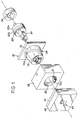
- the device has a body 10, a first inlet channel 12 for a first molten plastic 11 and a second inlet channel 14 for a second molten plastic 13.
- a first and a second extruders, represented symbolically, and respectively designated by the references 16 and 18 are intended to supply respectively the first inlet channel with the first plastic material fondue and the second inlet channel with the second plastic material fondue.
- the body 10 comprises, successively arranged axially in the direction of flow of the first plastic, indicated by arrow F, a intermediate channel 20 connected to the first input channel 12 and a channel extrusion 22 whose wall has several longitudinal facets (not shown in the sectional view) which are used to define the external contour of the shaped part manufactured using the device.
- this device comprises an axial core extrusion 24 having a first section 24a disposed in the channel intermediate 20 and a second section 24b arranged in the channel extrusion 22.
- the space 26 formed between the second section 24b and the wall of the extrusion channel 22 serves to define the shape of the profiled part.
- the second section of the core defines the internal contour of the profile and the wall of the extrusion channel defines its external contour.
- the second input channel 14 has an input 28 connected to the second extruder 18 and an outlet end 30 connected to the channel extrusion 22.
- the second plastic material 13 comes into contact of the first plastic when the internal portion of the part profile is already defined by the channel and the extrusion core.
- the area connection between the outlet end of the second inlet channel and the channel can be located at the entrance 22 'of the extrusion channel or, as this is the case in the example shown, slightly downstream of this entry, of so that a first part 22a of the extrusion channel is made, in which the internal portion of the profiled part takes its shape.
- the two layers of the profiled part are present.
- the extrusion device consists of an assembly of stacked or nested pieces, and fixed relative to each other.
- the extrusion core 24 is mounted in indicated rings, from upstream to downstream in the direction of flow F of the first plastic material, by the references 32a, 32b and 32c.
- Another ring 34 is mounted against the ring 32a.
- the first section 24a of the core extends substantially from the ring 34 to the ring 32c.
- the internal peripheries of these rings define the channel intermediate 20, the shape of which gradually evolves from upstream to downstream until substantially defining the external contour of the profiled part.
- the shape of the first section 24a of the extrusion core gradually evolves from upstream to downstream until defining the outline internal profile. From the ring 32c, the core and the extrusion channel keep essentially the same shape: the one we want to give to the profiled part.
- the rings are mounted inside a hollow part inner 36, itself fitted into a hollow outer piece 38, that we will describe more precisely below.
- the extrusion core is supported in the extrusion channel by supporting webs or ribs, such as web 33, shown schematically in lines interrupted, which connects it to the internal periphery of the ring 32b.
- the wall of this channel is defined by the internal periphery of two pieces 40 and 42 fixed to each other, the outlet end of the piece downstream 42 defining the extrusion nozzle 44, which gives its final shape to the profiled part.
- the downstream elements of the die extrusion including for example a calibration and cooling as well as a profile advancement system, are symbolically represented and designated by the reference 46.
- an upstream hollow part 48 is connected to the upstream face of the internal part 36, and provided with an axial bore constituting the first channel 12, and connected to the intermediate channel 20.
- the device includes means for regulating the flow of the second plastic material 13 in the second inlet channel 14 and to determine, at the outlet end 30 of the latter, a homogeneous distribution of this second plastic material on the external contour of the profiled part.
- Figure 6 shows the cross section of this part 50.
- its external contour 52 comprises a plurality of segments inclined one by compared to others and of which, for the sake of simplification, certain segments only are indicated by the reference numerals 52a, 52b and 52c.
- This external contour also has ribs 53a, 53b, 53c and 53d and grooves 54a, 54b and 54c.
- the internal portion 56 of the profiled part 50 which constitutes its core or the heart, is made from the first plastic. It involves, in a known manner, recesses and connecting webs of which only some are indicated by the references 57a, 57b or 57c.
- the profile also comprises an outer layer 57 produced in a second plastic material. To facilitate representation, insofar as this outer layer is thin compared to the thickness of the different walls of the streamlined, it is only symbolized by a strong line. We see that it extends homogeneously over practically the entire contour of the profile. Alone certain determined zones are free thereof, such as the grooves 54a, 54b and 54c, which is voluntary and due to a particular configuration of the extrusion nozzle, as will be explained below.
- the second input channel 14 has an adjustment portion 60 which has an input 62 and which is provided with means for regulating the speed flow of the second plastic material 13, towards a given facet of the wall of the extrusion channel 22, as a function of the distance, measured according to the flow path of the second plastic material, between the inlet 62 of the adjustment portion and this facet.
- the flow path is the path that follows the second plastic to go from the entry of the portion of adjustment of the second input channel to the face of the room contour profiled that it will cover.
- the second setting portion comprises a first part of given section, on which the speed of flow is substantially constant at all points, and a second part, of reduced section, on which the flow speed is slowed down.
- the conformation of this second part is adapted to the contour of the part profile which is covered with the second plastic material.
- the second input channel comprises a diffusion channel 66, the outlet of which constitutes a zone generally annular located around the extrusion channel, and in which the flow velocity is made homogeneous.
- the exit from this channel diffusion then constitutes the input of the adjustment portion 60, which allows to facilitate speed adjustment since it is carried out from a speed homogeneous flow over an entire contour surrounding the profile.
- the output of the broadcasting channel is constituted by its substantially annular front end, designated by the reference 62 since it also constitutes the input to the adjustment portion 60.
- the channel broadcast includes means for determining a second rate substantially uniform plastic material on this front end.
- this flow rate is determined substantially uniform by shaping the diffusion channel into two parts.
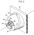
- the inner hollow part 36 has an outer periphery 68 having generally the shape of a truncated cone flared towards the rear, that is to say in the opposite direction to the arrow F in FIG. 2.
- This part 36 includes a through recess 70, through which the extrusion core 24 passes. made, as seen in Figure 2, the inner periphery of this recess through 70 serves to support the rings 34, 32a, 32b and 32c previously mentioned, inside which is a part of the extrusion core.
- the outer hollow part 38 is capable of fitting onto the inner hollow part 36 and for this purpose has a through recess 72 in which is housed the generally frustoconical external periphery of the part 36.
- a space is formed between the outer periphery 68 of the part 36 and the inner periphery 72 of room 38.
- This space constitutes the diffusion channel 66.
- the first part 74 of this broadcast channel is a groove in which the second plastic flows relatively quickly, while its second part 76 has a section such that the flow is slower there.
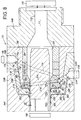
- Figure 2 is an axial section through the geometric axis A of extrusion channel.
- the cutting plane constitutes a plane of symmetry of the trunk of cone corresponding to the overall shape of the outer periphery 68 of the inner hollow part 36.
- two ends 74a and 74b of the throat 74 are cut, and the hidden half of this throat is indicated by broken lines.
- half of the throat 74 has the shape of a half-turn of propeller whose first end 74a, that which is located furthest behind, is directly connected to input 28 of the second inlet channel 14.
- the shape of the second half of the groove 74 can be deduced by symmetry with respect to the section plane of FIG. 4. In fact, the shape overall of this groove is best visible in Figures 1 and 3. Both ends of each half-turn are connected to the two ends of the other half-turn, in junction zones which correspond to the ends 74a and 74b indicated in FIG. 2, so that the pouring throat is keep on going.
- this groove poured in the form of a first groove 75a, constituted by two half-turns propeller, made on the outer periphery 68 of the part 36, and a second groove 75b, of similar shape, produced on the internal periphery 72 of the part 38.
- first groove 75a constituted by two half-turns propeller
- second groove 75b of similar shape, produced on the internal periphery 72 of the part 38.
- a groove could be obtained of the same type by machining only one deeper groove on the outer periphery 68 of the part 36 or on the inner periphery 72 of the Exhibit 38.
- the second part 76 of the diffusion channel extends between this groove 74 and the front end 62 of this channel, and is formed by the space interstitial formed between the two frustoconical surfaces of the same angle at the apex, respectively formed on the outer periphery 68 of the part 36 and on the internal periphery 72 of the part 38, at the front of the pouring groove.
- These two frustoconical surfaces are respectively designated by the references 78 and 80.
- the outer periphery 68 of the part 36 has, from the front towards the rear, a first frustoconical surface 78, the groove 75a, and a second frustoconical surface 79.
- the periphery internal 72 of the part 38 has a first frustoconical surface 80, the groove 75b and a second frustoconical surface 81.
- the frustoconical surfaces 78 and 80 provide between them the second part of the diffusion channel
- the grooves 75a and 75b form the pouring throat
- the frustoconical surfaces 79 and 81 are adjusted one on the other to avoid that the second plastic material does not rise backwards.
- Front end 74c of the throat 74 is obviously directly open on the second part of the broadcast channel.
- the thickness of the space forming this second part is substantially constant and less than the depth of the pouring groove.
- the points M 1 , M 2 and M 3 are indicated in FIG. 2 to better explain the path of the second plastic material from its entry into the second inlet channel 14. To go from point M 1 to point M 2 , the fluid particles will only have to travel a relatively short route, while the route is much longer from point M 1 to point M 3 , since it goes around the extrusion channel.
- the particular conformation of the diffusion channel makes it possible for the fluid particles arriving at the same time at least M 1 to also arrive at the point M 2 and M 3 at the same time. Indeed, from point M 1 to point M 2 , the path takes place almost entirely in the second part 76 of the diffusion channel, therefore slowly.
- the fluid particles going from point M 1 to point M 3 first cross the half-circumference of the pouring groove to go to point M ' 1 , a path on which the flow is rapid due to the relatively large section of the pouring groove compared to that of the second part of the diffusion channel, and only a very small portion of the path is made, between point M ' 1 and point M 3 , in the second part of section scaled down.
- points M 2 and M 3 are chosen which are diametrically opposite.
- the helical shape of the pouring groove makes it possible for particles arriving at the same time at point M 1 to also all arrive at the same time at the front end 62 of the diffusion channel.
- the flow is therefore substantially uniform over this front end, so that the flow parameters are substantially the same over the entire circumference of the inlet of the adjustment portion 60 of the second inlet channel.
- the inner hollow part 36 has a front face 84, produced on a front end portion 82 and extending substantially radially, from the front end 62 of the diffusion channel 66, to the channel extrusion 22.
- This front face constitutes the upstream wall of the adjustment portion 60.
- the downstream wall of this adjustment portion is produced by the rear face of the downstream part 40, provided with a through hole whose contour 86 constitutes, at less on an axial section, the wall of the extrusion channel.
- the rear 88 of this part is substantially radial, or, at least has a substantially radial portion 87 located opposite the front face 84 of the hollow junction piece 82 to form the downstream wall of the portion of setting 60. The latter therefore consists of the space provided between the sides 84 and 87.
- At least one of the faces 84 and 87 has at least one swollen zone locally reducing the cross-section of the adjustment portion.
- this bulged area is constituted by a step 90 located on the front face 84 and surrounding the opening of this last, while the part of the rear face 87 of the part 40 used for constitute the downstream wall of the adjustment portion is planar.
- the part front end 82 surrounds the extrusion core 24, and the space provided between the internal periphery 83 of this part 82 and the core 24 constitutes a first part 22a of the extrusion channel 22.
- This first part is located upstream of the arrival of the second plastic material 13 in the channel extrusion, and therefore constitutes an upstream part of this channel, on which only the first plastic material 11 is present, and serving to define the internal portion of the profiled part.
- the part 36 could be made in one piece with the part 82.
- this part consists of a junction piece 82 placed around the extrusion core, at the front end of the hollow part 36, by embedding in the latter.
- this front face 84 is integral with the part 36 (by fixing or by manufacturing in one piece).
- the first part 22a of the extrusion channel substantially corresponds to the section formed between the internal contour 83 of this part 82 and the extrusion core 24.
- the extrusion channel comprises a second part 22b, located at downstream of the arrival of the second plastic material 13, the wall of which serves to define the external contour of the profiled part provided with its external layer.
- the profile of the extrusion core remains identical on the two parts 22a and 22b of the extrusion channel.
- walking or part in projection 90 of the front face 84 has an outer edge 92 and an inner edge 94 which follows the outline of the through hole of this part. Therefore, the shape of this internal edge 94 defines the outline of the internal portion of the profiled part.
- the front end 62 of the diffusion channel 66 is at the level of the circular outer edge 96 of the front face 84.
- the distance between the internal edge 94 and the outer edge 92 is maximum.
- the points P ' 1 and P' 2 of the outer edge which correspond to the points P 1 and P 2 of the inner edge are found practically situated on the circular edge 96.
- the fluid particles of second plastic material arriving at the same time on the circular edge 96 will also reach the points P 1 , P 2 , P 3 and P 4 at the same time, so that the second plastic material will be distributed. homogeneously around the contour of the profiled part.
- the projecting part 90 has a portion plane 90a, which extends transversely to the direction longitudinal A of the extrusion core 24, and whose free edge constitutes the outer edge 92 of this projecting part.
- This flat portion 90 has a constant thickness, but it's its width, that is to say its dimension transverse to the axis A of the extrusion core, which varies and thus makes it possible to adjust the flow rates of the second plastic.
- the outer edge 92 is an inclined face, which allows passage without jolts of the current part of the face 84, to the projecting part.
- the projecting part also has a portion 90b inclined towards the extrusion channel, the free edge of which constitutes the internal edge 94 of this protruding part.
- the through hole of the downstream part 40 has a part rear 86 'flared towards the rear, situated opposite the inclined portion 90b and at a substantially constant distance from the latter.
- the inclined portion 90b allows to modify the direction of this flow until bringing it, in exit the second input channel, substantially tangential to the direction extrusion F.
- the front face 84 could be globally convex. This convexity would be stronger or more abrupt in areas where you want to slow down flow (i.e. in areas where the internal edge 94 is close to the circular edge 96), and less strong in the areas where not want to slow the flow too significantly (i.e. in areas for which the internal edge 94 is far from the edge circular 96).
- front face 84 is easily modifiable, this which would allow, with the same tool, to manufacture different profiles having the same core, but whose outer layers could differ by their thickness or by their distribution on the contour or, only, on certain faces. To do this, we can take advantage of using a junction piece 82 independent and, therefore, interchangeable.
- the wall of the second part 22b of the extrusion channel has a shape similar to that of the first part 22a.
- the spacing e 'between the wall of the second part 22b and the core extrusion 24 is greater than the spacing e between the wall of the first part 22a of the extrusion channel and the extrusion core 24.
- the diffusion channel 66 and the portion adjustment channel 60 of the second input channel allow the part to be endowed profiled with a thin homogeneous outer layer 57.
- This outer layer is marked by a strong line extending over practically the entire outer surface of the profiled part.
- some areas of the contour of the profile are devoid of of the outer layer. This is obtained thanks to a particular conformation of the extrusion nozzle, the front face of which is visible in FIG. 5.
- the wall 100 of the extrusion channel at its outlet We observe that this wall has exactly the same shape as the outside contour of the room profiled in FIG. 6.
- ribs 101, 102 and 103 giving their shapes to the grooves 54a, 54b and 54c. These ribs are only present in a terminal section of the extrusion channel, while that they are absent from most of this channel, and in particular from the part located just downstream from the outlet of the second inlet channel 14.
- the extrusion channel has a terminal section whose wall has at least one rib absent from the wall of others sections of this channel and which is used to define, on the external contour of the part profiled, a groove on which the external layer is absent.
- the nozzle extrusion had the shape of that of Figure 7, the entire contour of the profiled part would be covered by the outer layer.
- the shape of the nozzle of figure 7 corresponds to the wall of the part of the extrusion channel located between exit 30 of the second inlet channel and the terminal section of the extrusion channel (we recognize the facets which are used to produce the various segments of the external contour of the profiled part).
- the ribs 101 and 102 have been added in planar zones 101 'and 102', and that the rib 103 has been added in a groove 103 '.
- the device of FIGS. 1 to 3 makes it possible to distribute the outer layer over the entire external contour of the profiled parts, possibly at with the exception of certain grooves.
- the output of the broadcast channel can only be opened on one or more ring portions, on which the flow speed of the second plastic material is homogeneous and which correspond only to the covered part (possibly in several sections) of the profiled parts.
- the device 110 makes it possible to produce profiled parts with two outer layers.
- a third inlet channel 214 supplied with third plastic material 213 by a third extruder 218.
- the device comprises means for regulating the flow of the third plastic material in the third input channel 214 and to determine, at the output end 230 of the latter, a homogeneous distribution of said third plastic material on the external contour of the profiled part or, at least, on a part of this outline to be covered by the third plastic material.
- the conformation of the third input channel is analogous to that of the second, and the output 230 of this third channel opens into the extrusion channel 122 downstream of the area in which leads to exit 130 of the second channel 114.
- the third channel inlet 214 has a broadcast channel 266, the outlet of which generally annular 262 constitutes the entry of an adjustment portion 260.
- the broadcast channel 166 of the second input channel 114 is formed between the periphery external 178, generally frustoconical, of part 136 and the periphery internal 270, generally frustoconical, of part 236.
- the portion of setting 160 of this channel it is formed between the front face 184 and a wall downstream 187 constituted by the rear face of a front end portion 282 substantially radial from part 236.
- the third input channel 214 includes a broadcast channel 266, formed by a frustoconical space 276 and a groove 274 in two half-turns propeller, and formed between the outer periphery 278 generally frustoconical of the intermediate part 236 and the internal periphery 272, also generally frustoconical, from external part 238.
- This third channel 214 also includes an adjustment portion 260, the section of which varies, formed between the substantially radial front face 284 of part 282 of part 236 and a substantially radial downstream wall 287 formed on the rear face of a part 240 of the part 238.
- parts 282 and 240 can be parts independent or respectively to form one with parts 236 and 238.
- the extrusion channel 122 has a first part 122a, located upstream of exit 130 of channel 114 and of current section e, a second part 122b, located between outputs 130 and 230, and of section current e 'greater than e, and a third part 122c, located downstream of the output 130 and of current section e '' greater than e '.
- n input channels of the same can be realized so that channels 114 and 214 and connect them successively to the channel extrusion, upstream of which is connected the first inlet channel.
- the inputs 128 and 228 of the second and third input channels are practically diametrically opposite, for reasons of space related to the presence of extruders 118 and 218. In general, it suffices that they are angularly offset.
- the device which has just been described is used to implement a method to produce a hollow profiled part having an external contour which, in cross section, comprises a plurality of segments, and comprising a internal portion or core in a first plastic material and at least a second external made of a second plastic material.
- the first extruder 16 or 116 we feeds the first input channel 12 or 112 with the first material melted plastic 11 or 111, we carry out the flow of this first plastic in the intermediate channel 20 or 120 and in the channel extrusion 22 or 122 to extrude the internal portion of the profiled part, and, using at least the second extruder 18, 118 or 218, is fed at least the second input channel 14, 114 or 214 with at least the second molten plastic material 13 and the flow of this second plastic material in the extrusion channel or, more precisely, on said internal portion of the profiled part for extruding, on this portion internal, the external layer of this part.
- the device which has just been described, in one or other of its variants, is shaped so that any zone of turbulence or stopping the flow of one or other of the plastics is avoided.
- the plastic may stay in such a place for too long areas, and therefore to be exposed to too high temperatures, which would degrade.
- this device allows to extrude the choice of materials heat sensitive or heat resistant materials.
Landscapes
- Engineering & Computer Science (AREA)
- Mechanical Engineering (AREA)
- Manufacturing & Machinery (AREA)
- Extrusion Moulding Of Plastics Or The Like (AREA)
Claims (9)
- Extrusionsvorrichtung zur Herstellung eines Hohlprofilteils (50), das eine Außenkontur (52) aufweist, die im Querschnitt eine Mehrzahl von Segmenten (52a, 52b, 52c) aufweist, und ein Innenteil (56) enthält, das aus einem ersten Kunststoffmaterial und zumindest einer Außenschicht (57) hergestellt ist, die aus einem zweiten Kunststoffmaterial hergestellt ist und sich zumindest über einen Teil, den sogenannten "abgedeckten Teil", der Außenkontur erstreckt, welche Vorrichtung enthält:einen ersten Einlaßkanal (12),eine erste Strangpresse (16), die zum Speisen des ersten Einlaßkanals (12) mit einem ersten geschmolzenen Kunststoffmaterial (11) bestimmt ist,einen Körper (10), der nacheinander axial in Strömungsrichtung (F) des ersten Kunststoffmaterials (11) angeordnet einen Zwischenkanal (20), der mit dem ersten Einlaßkanal (12) verbunden ist, und einen Extrusionskanal (22) enthält, dessen Wandung mehrere Längsfacetten zum Definieren der Außenkontur des Profilteils aufweist,einen axialen Extrusionskern (24), der einen ersten Abschnitt (24a), der im Zwischenkanal (20) angeordnet ist, und einen zweiten Abschnitt (24b) aufweist, der im Extrusionskanal (22) angeordnet ist, wobei der zwischen dem zweiten Abschnitt und der Wandung des Extrusionskanals vorhandene Zwischenraum (26) zur Bestimmung der Form des Profilteils dient, wobei der zweite Abschnitt des Kerns die Innenkontur definiert und wobei die Wandung des Extrusionskanals die Außenkontur definiert,einen zweiten Einlaßkanal (14), der einen Einlaß (28) und ein Auslaßende (30) hat, das mit dem Extrusionskanal (22) verbunden ist, undeine zweite Strangpresse (18), die zum Speisen des zweiten Einlaßkanals (14) mit einem zweiten geschmolzenen Kunststoffmaterial (13) bestimmt ist,welche Vorrichtung Mittel aufweist, um den Fluß des zweiten Kunststoffmaterials (13) im zweiten Einlaßkanal (14) zu regeln, und um am Auslaßende (30) des letzteren eine homogene Verteilung des zweiten Kunststoffmaterials auf den abgedeckten Teil der Außenkontur des Profilteils (50) zu bestimmen, welche Vorrichtung ferner ein inneres Hohlteil (36), das eine Durchgangsausnehmung (70) aufweist, durch die der Extrusionskern (24) hindurchgeht, und ein äußeres Hohlteil (38) aufweist, das auf das innere Hohlteil aufsteckbar ist, welche Teile (36, 38) aufeinandergesteckt zwischen sich einen Diffusionskanal (66) für das zweite Kunststoffmaterial (13) einschließen, welcher Kanal einen Teil des zweiten Einlaßkanals (14) bildet und einen ersten Bereich (74) enthält, der die Form von zwei schraubenartigen Halbwindungen hat, die zu einer Symmetrieebene des Außenumfangs (68) des inneren Hohlteils (36) plansymmetrisch sind und in dieser Ebene mit ihren beiden Endabschnitten (74a, 74b) aufeinandertreffen, um eine kontinuierliche Gießkehle zu bilden, welcher erster Verbindungsbereich (74a) der Halbwindungen gegenüber dem zweiten Verbindungsbereich (74b) nach hinten versetzt und direkt mit dem Einlaß (28) des zweiten Einlaßkanals (14) verbunden ist, welcher Diffusionskanal (66) ferner einen zweiten Bereich (76) enthält, der sich zwischen der Gießkehle (74) und dem vorderen Ende (62) dieses Kanals (66) erstreckt und durch den Zwischenraum gebildet ist, der zwischen den einander gegenüberliegenden Seiten des Außenumfangs (68) des Innenteils (36) und des Innenumfangs (72) des Außenteils (38) vorhanden ist,
dadurch gekennzeichnet, daß das innere Hohlteil (36) einen vorderen Endabschnitt (82) mit einer Vorderseite (84) aufweist, die sich im wesentlichen radial zwischen dem vorderen Ende (62) des Diffusionskanals (66) und dem Extrusionskanal (22) erstreckt,daß sie ein nachgelagertes Teil (40) enthält, das mit einer Durchgangsbohrung versehen ist, deren Kontur (86) zumindest über einem axialen Abschnitt die Wandung des Extrusionskanals (22) bildet, welches nachgelagerte Teil eine Hinterseite (87) aufweist, die im wesentlichen radial verläuft und der Vorderseite (84) des vorderen Endabschnitts (82) gegenüberliegt,daß der zweite Einlaßkanal (14) einen Verstellteil (60) enthält, der durch den Raum zwischen der Hinterseite (87) des nachgelagerten Teils (40) und der Vorderseite (84) des vorderen Endabschnitts (82) gebildet ist,und daß dieser Verstellteil einen veränderlichen Querschnitt aufweist, wodurch Mittel gebildet sind, um, ausgehend von einem im wesentlichen einheitlichen Durchsatz des zweiten Kunststoffmaterials am vorderen Ende (62) des Diffusionskanals (66), die Strömungsgeschwindigkeit des zweiten Kunststoffmaterials zu einer gegebenen Facette der Wandung des Extrusionskanals (22) zu regeln als Funktion des entlang des Strömungsweges des zweiten Kunststoffmaterials gemessen Abstandes zwischen dem Einlaß (62) des Verstellteils (60) und dieser Facette, wobei die Querschnittsveränderungen des Verstellteils (60) mit Hilfe von zumindest einem Verstärkungsbereich (90) durchgeführt werden, mit dem zumindest eine der zwischen dem Verstellteil (60) vorgesehenen Seiten (87, 84) versehen ist und der den Querschnitt des letztgenannten bereichsweise verkleinert. - Vorrichtung nach Anspruch 1, dadurch gekennzeichnet, daß der Außenumfang (68) des inneren Hohlteils (36) insgesamt die Form eines nach hinten erweiterten Kegelstumpfs aufweist, wobei der zweite Teil (76) des Diffusionskanals (66) zwischen zwei kegelstumpfförmigen Flächen (78, 80) mit gleichem Scheitelwinkel vorgesehen ist, welche jeweils am Außenumfang (68) des inneren Teils (36) und am Innenumfang (72) des äußeren Teils (38) gebildet sind, wobei die Dicke des den zweiten Teil bildenden Raums im wesentlichen gleichbleibend und geringer als die Tiefe der Gießkehle (74) ist.
- Vorrichtung nach Anspruch 1 oder 2, dadurch gekennzeichnet, daß die Hinterseite (87) des nachgelagerten Teils (49) im wesentlichen eben ist, daß der vordere Endabschnitt (82) den Extrusionskern umschließt und der zwischen dem Innenumfang dieses Teils und dieses Kerns vorhandene Zwischenraum einen ersten Teil (22a) des Extrusionskanals (22) bildet, der zum Definieren des Innenbereichs des Profilteils dient, welcher Kanal einen zweiten Teil (22b) enthält, der dem ersten Teil (22a) nachgelagert ist und dessen Wandung zum Definieren der Außenkontur des Profilteils mit äußerer Schicht dient, daß die Vorderseite (84) des vorderen Endabschnitts (82) einen Vorsprungsteil (90) aufweist, der einen Außenrand und einen Innenrand aufweist, welcher der Kontur des Außenumfangs des vorderen Endabschnitts (82) folgt, und daß bei den Punkten (P1, P2) des Innenrands (94), welche dem vorderen Endabschnitt (62) des Diffusionskanals (66) radial am nächsten liegen, der Abstand zwischen dem Innenrand (94) und dem Außenrand (92) am größten ist, während bei den Punkten (P3, P4) des Innenrandes (94), welche vom vorderen Endabschnitt (62) des Diffusionskanals (66) am weitesten entfernt sind, der Abstand zwischen dem Innenrand (94) und dem Außenrand (92) am kleinsten ist.
- Vorrichtung nach Anspruch 3, dadurch gekennzeichnet, daß der Vorsprungsteil (90) einen ebenen Bereich (90a), der sich quer zur Längsrichtung (A) des Extrusionskerns (24) erstreckt und dessen freier Rand den Außenrand (92) des Vorsprungsteils (90) bildet, und einen zum Extrusionskanal geneigten Bereich (90b) aufweist, dessen freier Rand den Innenrand (94) dieses Teils bildet, und daß die Durchgangsbohrung des nachgelagerten Teils einen hinteren Bereich (86') aufweist, der nach hinten erweitert ist und in einem im wesentlichen konstanten Abstand diesem geneigten Bereich (90b) gegenüberliegt.
- Vorrichtung nach einem der Ansprüche 1 bis 4, dadurch gekennzeichnet, daß die Wandung des zweiten Teils (22b) des Extrusionskanals (22) eine analoge Form zu der des ersten Teils (22a) dieses Kanals hat, welcher Abstand (e') zwischen der Wandung dieses zweiten Teils und dem Extrusionskern größer ist als der Abstand (e) zwischen der Wandung des ersten Teils des Extrusionskanals und dem Extrusionskern.
- Vorrichtung nach einem der Ansprüche 1 bis 5, dadurch gekennzeichnet, daß der Extrusionskanal (22) einen Endabschnitt aufweist, dessen Wandung zumindest eine Rippe (101, 102, 103) enthält, welche an der Wandung der weiteren Abschnitte dieses Kanals nicht vorgesehen ist und dazu dient, an der Außenkontur (57) des Profilteils eine Rinne (54a, 54b, 54c) zu bestimmen, an der die Außenschicht weggelassen ist.
- Vorrichtung nach einem der Ansprüche 1 bis 6, dadurch gekennzeichnet, daß sie einen dritten Einlaßkanal (214) enthält, der mit einem dritten geschmolzenen Kunststoffmaterial (213) durch eine dritte Strangpresse (218) gespeist wird, einen Einlauf (228) hat und ein Auslaßende (230) aufweist, das mit dem Extrusionskanal (122) nach dem Anschlußbereich des Auslaßendes (130) des zweiten Einlaßkanals (114) verbunden ist, welcher dritte Einlaßkanal (214) eine dem zweiten Einlaßkanal ähnliche Konfiguration hat.
- Vorrichtung nach Anspruch 7, dadurch gekennzeichnet, daß, sei n eine ganze Zahl größer als 1, sie n+1 Einlaßkanäle aufweist, welche neben dem ersten und dem zweiten Einlaßkanal (112, 114) n-1 weitere Einlaßkanäle (214) enthalten, deren Gestalt derjenigen des zweiten Einlaßkanals ähnlich ist und deren Auslaufenden jeweils nacheinander in stromabwärts laufender Richtung mit dem Extrusionskanal (122) verbunden sind.
- Verfahren zur Herstellung eines Hohlprofilteils (50) mit einer Außenkontur (52), die im Querschnitt eine Mehrzahl von Segmenten (52a, 52b, 52c) aufweist, und mit einem Innenteil (56) aus einem ersten Kunststoffmaterial und zumindest einer Außenschicht (57), die aus einem zweiten Kunststoffmaterial hergestellt ist, dadurch gekennzeichnet,daß eine Vorrichtung nach einem der Ansprüche 1 bis 8 vorgesehen wird, daß mit Hilfe der ersten Strangpresse (16, 116) der erste Einlaßkanal (12, 112) mit dem ersten geschmolzenen Kunststoffmaterial (11, 111) gespeist wird, man das Fließen dieses ersten geschmolzenen Kunststoffmaterials in dem Zwischenkanal (20, 120) und in dem Extrusionskanal (22, 122) realisiert, um den Innenbereich des Hohlprofils zu extrudieren, und mit Hilfe zumindest der zweiten Strangpresse (18, 118; 218) zumindest der zweite Einlaßkanal (14, 114, 214) mit zumindest dem zweiten geschmolzenen Kunststoffmaterial (13, 113; 213) gespeist wird und man das Fließen dieses zweiten Kunststoffmaterials in dem Extrusionskanal im Innenbereich des Profilteils realisiert, um in diesem Innenbereich die Außenschicht dieses Teils zu extrudieren.
Applications Claiming Priority (2)
| Application Number | Priority Date | Filing Date | Title |
|---|---|---|---|
| FR9504535A FR2732923B1 (fr) | 1995-04-14 | 1995-04-14 | Dispositif d'extrusion pour pieces profilees bicouches |
| FR9504535 | 1995-04-14 |
Publications (2)
| Publication Number | Publication Date |
|---|---|
| EP0737561A1 EP0737561A1 (de) | 1996-10-16 |
| EP0737561B1 true EP0737561B1 (de) | 1999-08-25 |
Family
ID=9478148
Family Applications (1)
| Application Number | Title | Priority Date | Filing Date |
|---|---|---|---|
| EP96400787A Expired - Lifetime EP0737561B1 (de) | 1995-04-14 | 1996-04-12 | Extrusionsdüse für Zweischichtprofilen |
Country Status (6)
| Country | Link |
|---|---|
| US (1) | US5733491A (de) |
| EP (1) | EP0737561B1 (de) |
| BR (1) | BR9601361A (de) |
| DE (1) | DE69603898T2 (de) |
| ES (1) | ES2136373T3 (de) |
| FR (1) | FR2732923B1 (de) |
Families Citing this family (17)
| Publication number | Priority date | Publication date | Assignee | Title |
|---|---|---|---|---|
| FR2767740B1 (fr) * | 1997-08-29 | 1999-10-08 | Alphacan Sa | Procede de fabrication d'un profile composite en matiere plastique, installation pour la mise en oeuvre du procede, et profile composite en matiere plastique |
| ATE222847T1 (de) * | 1998-04-28 | 2002-09-15 | Sendenhorst Kunststoffroehren | Verfahren zum herstellen eines profils für fenster oder türen |
| DE19852082C5 (de) * | 1998-11-11 | 2006-01-19 | Fraunhofer-Gesellschaft zur Förderung der angewandten Forschung e.V. | Verbundprofil, insbesondere für Fensterrahmen |
| US7469905B2 (en) | 2000-11-30 | 2008-12-30 | Springseal Inc. | Permanently lubricated film gasket and method of manufacture |
| US6458301B1 (en) | 2001-08-27 | 2002-10-01 | Schlegel Corporation | Method for forming weatherseals from an interchangeable insert die assembly |
| US6783348B2 (en) * | 2001-09-26 | 2004-08-31 | Korea Plasys Corporation | Extrusion molding apparatus for product having wood pattern and extrusion molding method thereof |
| US20050206031A1 (en) * | 2004-03-17 | 2005-09-22 | American Maplan Corporation | Extrusion die |
| AT413357B (de) * | 2004-07-23 | 2006-02-15 | Gruber & Co Group Gmbh | Extrusionsdüse zum extrudieren von hohlprofilen |
| US7878792B2 (en) * | 2005-03-16 | 2011-02-01 | Greiner Tool. Tec Gmbh | Support arrangement for an extrusion tool and extrusion tool for moulding an object |
| US8727387B2 (en) * | 2008-05-27 | 2014-05-20 | Springseal, Inc. | Pipe coupling assembly |
| US8801049B2 (en) | 2011-04-29 | 2014-08-12 | Springseal, Inc. | Pipe coupling system and method |
| US9227353B2 (en) * | 2012-11-08 | 2016-01-05 | Solar Hydronics Corporation | Molding apparatus and method for operating same |
| CN103612378A (zh) * | 2013-12-11 | 2014-03-05 | 湖北凯乐科技股份有限公司 | 一种尼龙与聚乙烯护套双层共挤模具 |
| DE102018214671A1 (de) * | 2018-08-29 | 2020-03-05 | Greiner Extrusion Group Gmbh | Extrusionsvorrichtung und Extrusionsverfahren |
| CN109304850A (zh) * | 2018-09-30 | 2019-02-05 | 广东粤亚塑料制品有限公司 | 双色管道的生产方法及双色管道成型装置 |
| CN115782031B (zh) * | 2023-02-09 | 2023-04-25 | 浙江建华集团盛太塑料有限公司 | 一种珍珠棉生产设备及其工艺 |
| DE102023118744A1 (de) * | 2023-07-14 | 2025-01-16 | Salamander Industrie-Produkte Gmbh | Extrusionsdüse für Koextrusionswerkzeug |
Family Cites Families (17)
| Publication number | Priority date | Publication date | Assignee | Title |
|---|---|---|---|---|
| US2859476A (en) * | 1955-08-01 | 1958-11-11 | Western Plastics Corp | Extrusion apparatus |
| US4189520A (en) * | 1972-09-22 | 1980-02-19 | Dynamit Nobel Aktiengesellschaft | Shaped structural members having improved lightfastness and weatherproofness |
| DE2246679C3 (de) * | 1972-09-22 | 1980-11-13 | Dynamit Nobel Ag, 5210 Troisdorf | Vorrichtung zum Extrudieren eines aus thermoplastischen Kunststoffen bestehenden Strangprofils mit einem Kernprofil und einer Deckschicht |
| DE2265035B2 (de) * | 1972-09-22 | 1981-02-05 | Dynamit Nobel Ag, 5210 Troisdorf | Strangpresse zum Herstellen eines Hohlstranges aus thermoplastischem Kunststoff mit einer Beschichtung aus einem weiteren thermoplastischen Kunststoff |
| DE2535286C3 (de) * | 1975-08-07 | 1979-01-25 | Dynamit Nobel Ag, 5210 Troisdorf | Verfahren zum Kalibrieren einer coextrudierten Profilleiste aus thermoplastischen Kunststoffen |
| US4208175A (en) * | 1976-12-17 | 1980-06-17 | Hpm Corporation | Coextrusion feedblock and process |
| US4130976A (en) * | 1977-03-07 | 1978-12-26 | Gerbruder Kommerling Kunststoffwerke G.M.B.H. | Frame for doors, windows and the like |
| US4118166A (en) * | 1977-07-22 | 1978-10-03 | The Bf Goodrich Company | Extrusion apparatus |
| US4280801A (en) * | 1979-05-30 | 1981-07-28 | Crompton & Knowles Corporation | Crosshead |
| IT1135542B (it) * | 1981-02-19 | 1986-08-27 | Mario Calcagni | Testa di estrusione per profilati per avvolgibili,infissi e simili,nonche' profilato ottenuto |
| US4655987A (en) * | 1982-10-12 | 1987-04-07 | Guillermo Zertuche | Method and apparatus for extruding tubular articles having several conduits |
| DE3616444A1 (de) * | 1986-05-15 | 1987-11-19 | Dynamit Nobel Ag | Fenster- und/oder tuerprofile aus kunststoffmaterial und verfahren zur herstellung dieser profile im extrusionsverfahren unter verwertung von kunststoffmaterial geringerer stabilitaet |
| US4723902A (en) * | 1986-08-21 | 1988-02-09 | Wheeling Stamping Company | Balanced flow extrusion crosshead and die assembly |
| US4738611A (en) * | 1987-03-04 | 1988-04-19 | Graham Engineering Corporation | Cross head die |
| US5186876A (en) * | 1989-01-27 | 1993-02-16 | Schaumstoffwerk Greiner Gesellschaft M.B.H | Process of making dimensionally stable section |
| US5106562A (en) * | 1989-12-28 | 1992-04-21 | American National Can Company | Extrusion methods and apparatus |
| IT1252023B (it) * | 1991-11-28 | 1995-05-27 | Sviluppo Settori Impiego Srl | Filiera per la produzione di profilati coestrusi |
-
1995
- 1995-04-14 FR FR9504535A patent/FR2732923B1/fr not_active Expired - Lifetime
-
1996
- 1996-04-10 US US08/628,991 patent/US5733491A/en not_active Expired - Lifetime
- 1996-04-12 ES ES96400787T patent/ES2136373T3/es not_active Expired - Lifetime
- 1996-04-12 DE DE69603898T patent/DE69603898T2/de not_active Expired - Lifetime
- 1996-04-12 EP EP96400787A patent/EP0737561B1/de not_active Expired - Lifetime
- 1996-04-15 BR BR9601361A patent/BR9601361A/pt not_active IP Right Cessation
Also Published As
| Publication number | Publication date |
|---|---|
| FR2732923A1 (fr) | 1996-10-18 |
| DE69603898T2 (de) | 2000-02-24 |
| EP0737561A1 (de) | 1996-10-16 |
| BR9601361A (pt) | 1998-01-13 |
| US5733491A (en) | 1998-03-31 |
| ES2136373T3 (es) | 1999-11-16 |
| DE69603898D1 (de) | 1999-09-30 |
| FR2732923B1 (fr) | 1997-07-04 |
Similar Documents
| Publication | Publication Date | Title |
|---|---|---|
| EP0737561B1 (de) | Extrusionsdüse für Zweischichtprofilen | |
| BE1005015A3 (fr) | Procede et appareillage destines a la formation d'un article presentant plusieurs densites et/ou geometries de cellules. | |
| CA2152804C (fr) | Conduit multicouche et filiere pour sa fabrication | |
| EP0406068B1 (de) | Vorrichtung zur Herstellung von durchsichtigen Kunststoffschichten, welche ein eingefärbtes filtrierendes Band in der Masse aufweisen | |
| CA2030071C (fr) | Cylindre pour un dispositif de coulee continue sur un ou entre deux cylindres | |
| FR2589437A1 (fr) | Dispositif de liaison entre deux feuilles de matiere plastique; sac equipe, pour sa fermeture, d'un tel dispositif | |
| FR2698551A1 (fr) | Dispositif pour la réalisation d'une surface mobile au moyen de lames articulées. | |
| FR2572988A1 (fr) | Poulie composee d'un roulement et d'un bandage en matiere plastique moulee | |
| FR2739001A1 (fr) | Procede et appareil pour mouler en continu un connecteur de fixation | |
| EP0179521A1 (de) | Einstellbarer Beschickungsblock für eine Koextrudierdüse | |
| EP3645236B1 (de) | Extrusionskopf mit kanälen zur herstellung von einsätzen in einem profilband zur herstellung eines luftreifens und entsprechendes extrusionsverfahren | |
| EP1343624B1 (de) | Extrusionsvorrichtung zur herstellung von produkten aus kautschukmischungen | |
| FR2767889A1 (fr) | Roue directrice de convertisseur de couple de rotation fabriquee par injection | |
| EP1028217A1 (de) | Fensterrahmen und Verfahren zu seiner Herstellung | |
| EP1677916B1 (de) | Spritzkopf für flüssiges produkt | |
| EP3740372B1 (de) | Werkzeug zum dreidimensionalen auftragen von material durch extrusion | |
| EP0494566A1 (de) | Vorrichtung zum Extrudieren von einem Profilelement mit einer hohlförmigen Struktur aus thermoplastischem Kunststoff. | |
| EP0756946A1 (de) | Stift dessen Gummihülse durch Ultraschallschweissen fixiert ist und dafür geeignete Gummihülse | |
| EP0031742A1 (de) | Extrusionsraum für eine kontrollierbare Ringkreisverteilung des extrudierten Materials und für einen inkorporierten Spritzkopf | |
| EP1762372B1 (de) | Vorrichtung zur Herstellung einer optischen Linse aus synthetischem Kunststoff | |
| EP1660236A1 (de) | Spritzkopf für fluidprodukt | |
| CA3144813A1 (fr) | Prefiliere de coextrusion multi-voies possedant un raidisseur traversant monolithique pouvant etre obtenu par fabrication additive | |
| BE1009797A5 (fr) | Dispositif d'extrusion de corps a structure en nid d'abeilles et procede pour la production de corps a structure en nid d'abeilles en utilisant le dispositif d'extrusion. | |
| FR2737751A1 (fr) | Rideau a lames | |
| FR2806955A1 (fr) | Tete d'extrusion |
Legal Events
| Date | Code | Title | Description |
|---|---|---|---|
| PUAI | Public reference made under article 153(3) epc to a published international application that has entered the european phase |
Free format text: ORIGINAL CODE: 0009012 |
|
| AK | Designated contracting states |
Kind code of ref document: A1 Designated state(s): BE DE ES IT NL |
|
| 17P | Request for examination filed |
Effective date: 19970123 |
|
| GRAG | Despatch of communication of intention to grant |
Free format text: ORIGINAL CODE: EPIDOS AGRA |
|
| 17Q | First examination report despatched |
Effective date: 19981022 |
|
| GRAG | Despatch of communication of intention to grant |
Free format text: ORIGINAL CODE: EPIDOS AGRA |
|
| GRAH | Despatch of communication of intention to grant a patent |
Free format text: ORIGINAL CODE: EPIDOS IGRA |
|
| GRAH | Despatch of communication of intention to grant a patent |
Free format text: ORIGINAL CODE: EPIDOS IGRA |
|
| GRAA | (expected) grant |
Free format text: ORIGINAL CODE: 0009210 |
|
| AK | Designated contracting states |
Kind code of ref document: B1 Designated state(s): BE DE ES IT NL |
|
| REF | Corresponds to: |
Ref document number: 69603898 Country of ref document: DE Date of ref document: 19990930 |
|
| REG | Reference to a national code |
Ref country code: ES Ref legal event code: FG2A Ref document number: 2136373 Country of ref document: ES Kind code of ref document: T3 |
|
| ITF | It: translation for a ep patent filed | ||
| PLBE | No opposition filed within time limit |
Free format text: ORIGINAL CODE: 0009261 |
|
| STAA | Information on the status of an ep patent application or granted ep patent |
Free format text: STATUS: NO OPPOSITION FILED WITHIN TIME LIMIT |
|
| 26N | No opposition filed | ||
| PGFP | Annual fee paid to national office [announced via postgrant information from national office to epo] |
Ref country code: NL Payment date: 20150313 Year of fee payment: 20 |
|
| PGFP | Annual fee paid to national office [announced via postgrant information from national office to epo] |
Ref country code: DE Payment date: 20150409 Year of fee payment: 20 Ref country code: ES Payment date: 20150423 Year of fee payment: 20 |
|
| PGFP | Annual fee paid to national office [announced via postgrant information from national office to epo] |
Ref country code: BE Payment date: 20150429 Year of fee payment: 20 Ref country code: IT Payment date: 20150423 Year of fee payment: 20 |
|
| REG | Reference to a national code |
Ref country code: DE Ref legal event code: R071 Ref document number: 69603898 Country of ref document: DE |
|
| REG | Reference to a national code |
Ref country code: NL Ref legal event code: MK Effective date: 20160411 |
|
| REG | Reference to a national code |
Ref country code: ES Ref legal event code: FD2A Effective date: 20160727 |
|
| PG25 | Lapsed in a contracting state [announced via postgrant information from national office to epo] |
Ref country code: ES Free format text: LAPSE BECAUSE OF EXPIRATION OF PROTECTION Effective date: 20160413 |