EP0675656A2 - Bewegtbildkodierungsvorrichtung - Google Patents
Bewegtbildkodierungsvorrichtung Download PDFInfo
- Publication number
- EP0675656A2 EP0675656A2 EP95104583A EP95104583A EP0675656A2 EP 0675656 A2 EP0675656 A2 EP 0675656A2 EP 95104583 A EP95104583 A EP 95104583A EP 95104583 A EP95104583 A EP 95104583A EP 0675656 A2 EP0675656 A2 EP 0675656A2
- Authority
- EP
- European Patent Office
- Prior art keywords
- coding
- frame
- picture
- signal
- moving picture
- Prior art date
- Legal status (The legal status is an assumption and is not a legal conclusion. Google has not performed a legal analysis and makes no representation as to the accuracy of the status listed.)
- Withdrawn
Links
Images


Classifications
-
- H—ELECTRICITY
- H04—ELECTRIC COMMUNICATION TECHNIQUE
- H04N—PICTORIAL COMMUNICATION, e.g. TELEVISION
- H04N19/00—Methods or arrangements for coding, decoding, compressing or decompressing digital video signals
- H04N19/42—Methods or arrangements for coding, decoding, compressing or decompressing digital video signals characterised by implementation details or hardware specially adapted for video compression or decompression, e.g. dedicated software implementation
- H04N19/436—Methods or arrangements for coding, decoding, compressing or decompressing digital video signals characterised by implementation details or hardware specially adapted for video compression or decompression, e.g. dedicated software implementation using parallelised computational arrangements
-
- H—ELECTRICITY
- H04—ELECTRIC COMMUNICATION TECHNIQUE
- H04N—PICTORIAL COMMUNICATION, e.g. TELEVISION
- H04N21/00—Selective content distribution, e.g. interactive television or video on demand [VOD]
- H04N21/40—Client devices specifically adapted for the reception of or interaction with content, e.g. set-top-box [STB]; Operations thereof
- H04N21/43—Processing of content or additional data, e.g. demultiplexing additional data from a digital video stream; Elementary client operations, e.g. monitoring of home network or synchronising decoder's clock; Client middleware
- H04N21/434—Disassembling of a multiplex stream, e.g. demultiplexing audio and video streams, extraction of additional data from a video stream; Remultiplexing of multiplex streams; Extraction or processing of SI; Disassembling of packetised elementary stream
- H04N21/4347—Demultiplexing of several video streams
-
- H—ELECTRICITY
- H04—ELECTRIC COMMUNICATION TECHNIQUE
- H04N—PICTORIAL COMMUNICATION, e.g. TELEVISION
- H04N19/00—Methods or arrangements for coding, decoding, compressing or decompressing digital video signals
- H04N19/60—Methods or arrangements for coding, decoding, compressing or decompressing digital video signals using transform coding
- H04N19/61—Methods or arrangements for coding, decoding, compressing or decompressing digital video signals using transform coding in combination with predictive coding
-
- H—ELECTRICITY
- H04—ELECTRIC COMMUNICATION TECHNIQUE
- H04N—PICTORIAL COMMUNICATION, e.g. TELEVISION
- H04N21/00—Selective content distribution, e.g. interactive television or video on demand [VOD]
- H04N21/20—Servers specifically adapted for the distribution of content, e.g. VOD servers; Operations thereof
- H04N21/23—Processing of content or additional data; Elementary server operations; Server middleware
- H04N21/236—Assembling of a multiplex stream, e.g. transport stream, by combining a video stream with other content or additional data, e.g. inserting a URL [Uniform Resource Locator] into a video stream, multiplexing software data into a video stream; Remultiplexing of multiplex streams; Insertion of stuffing bits into the multiplex stream, e.g. to obtain a constant bit-rate; Assembling of a packetised elementary stream
- H04N21/2365—Multiplexing of several video streams
Definitions
- the present invention relates to a device for high performance coding a plurality of moving image signals and broadcasting or transmitting them simultaneously and, particularly, to a moving image coding device thereof, which uses an inter-frame or inter-field prediction.
- a transmission path for transmitting an FM modulated NTSC signal has a band width of about 27 MHz. This band width allows a digital data of about 30 Mbps to be transmitted. Since, when the NTSC signal is coded by using the motion compensation inter-frame prediction, a sufficient image quality is obtainable by about 10 Mbps, it is possible to transmit three kinds of moving image through the transmission path of 30 Mbps.
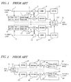
- Fig. 1 is a block diagram of an example of a conventional moving picture coding device for digitally broadcasting two kinds (2 channel) of picture signal. There are provided two coders which are basically the same and code the respective moving pictures.
- a signal of a picture a inputted from an input terminal 1 is supplied to a subtracter 5 and a picture type setting device 41.
- a signal of a picture b inputted from an input terminal 11 is supplied to a subtracter 15 and a picture type setting device 42.
- the subtracter 5 subtracts a prediction signal from the input signal a.
- a residual signal obtained by the subtracter 5 is supplied to a coder 6.
- the DCT Discrete Cosine Transform
- a coefficient obtained by the DCT is quantized with a predetermined step width and variable-length coded.
- a data train thus compressed is supplied to a buffer 43 and a decoder 8.
- the buffer 43 absorbs a variation of the amount of code caused by the variable-length coding to make a transfer rate of the data train substantially constant and supplies it to a multiplexer 100.
- the decoder 8 performs a processing which is reverse to that performed by the coder 6 and outputs a reproduced residual signal.
- An adder 7 adds a prediction signal supplied from an inter-frame predictor 3 to the reproduced residual signal supplied from the decoder 8.
- the reproduced picture signal output from the adder 7 is sent to the inter-frame predictor 3.
- the inter-frame predictor 3 delays the reproduced picture signal by 1 frame and outputs it as a inter-frame prediction signal which is supplied to the subtracter 5 and the adder 7 through a switch 4.
- a movable terminal of the switch 4 is connected to the inter-frame predictor 3 when a picture type information supplied from the picture type setting device 41 indicates a unidirectionally predictive frame (P frame: Predictive-Frame) and is connected to the 0 value and cuts the predictive signal when the picture type is an intra-frame (I frame).
- P frame Predictive-Frame
- I frame intra-frame
- the P frame means a frame which is coded by the inter-frame prediction coding by using a predictive signal produced from a preceding frame and the I frame means a frame which is intra-frame coded independently without using the inter-frame prediction.
- the selection of a frame to be set as the I frame is performed by the picture type setting device 41 with a frame sync timing of the input picture.
- the picture type information from the picture type setting device 41 is supplied to the switch 4 and multiplexed with the data train from the buffer 43 by the multiplexer 100 and sent to a decoding device.
- the timing of the I frame setting may be every 20 to 30 frames for a high speed search and/or error reflesh during a VTR recording.
- the amount of code of the I frame is 5 to 10 times that of the P frame, the amount of code generated varies frame to frame considerably. In order to absorb such large variation, a buffer having large capacity is required.
- an independent picture is set not frame unit but a portion of a frame which may be one tenth of one frame and the portion is shifted every reflesh so that the whole image is refleshed for about 1 second.
- the buffer capacity may be small.
- a search picture during a VTR recording is divided, causing a monitor to be difficult.
- the multiplexer 100 multiplexes the output of the buffer 43, which is the data train of the picture a, with an output of the buffer 44, which is a data train of the picture b, and outputs a multiplexed data train from a data output terminal 20.
- the decoding device shown in Fig. 2 is one to be associated with the coding device shown in Fig. 1.
- a multiplexed data train input from a data input terminal 31 is demultiplexed to data trains of the pictures a and b.
- the data train of the picture a is supplied to a buffer 53 and the data train of the picture b is supplied to a buffer 64.
- the data train of the picture a is written in the buffer 53 at a constant speed, read out therefrom at a speed matched with a timing of a decoding processing to be performed in a decoder 58 and supplied to the decoder 58.
- the decoder 58 performs a similar processing to that performed in the coding device shown in Fig. 1 and outputs a reproduced residual signal.
- the reproduced residual signal is supplied to an adder 57.
- the adder 57 adds a predictive signal supplied from an inter-frame predictor 55 to the reproduced residual signal and outputs a reproduced picture signal of the picture a.
- the reproduced picture signal is supplied to the inter-frame predictor 55 and an output terminal 59.
- the inter-frame predictor 55 delays the reproduced picture signal by 1 frame and outputs it as an inter-frame predictive signal.
- the inter-frame predictive signal is supplied to the adder 57 through a switch 54.
- the switch 54 cuts the inter-frame predictive signal according to the picture type information separated by a demultiplexer 33.
- the buffer capacity corresponds to a maximum variation with respect to a fixed transfer rate of the generated code amount. The larger the variation requires the larger the capacity.
- the delay time between the data input to the buffer on the coding side and the data output from the buffer on the decoding side becomes constant. That is, when the delay is large due to accumulation of a large amount of data in the coding side buffer, the amount of data accumulated in the decoding side buffer and hence the delay is small. On the contrary, when the delay is small due to small amount of data accumulated in the coding side buffer, the amount of data accumulated in the decoding side buffer and hence the delay becomes large. Therefore, a total amount of data accumulated in the both buffers is equal to the capacity of one buffer. Further, the capacity of the coding side buffer is the same as that of the decoding side buffer and the both buffers operate complementarily.
- the amount of delay is a quotient of a division of the capacity of one buffer by the transfer rate. For example, when the buffer capacity is 1 Mbit and the transfer rate is 5 Mbps, the delay becomes 0.2 seconds. With the same buffer capacity, the lower the transfer rate provides the larger the delay and, with the same transfer rate, the larger the buffer capacity provides the larger the delay.
- the amount of code of the intra-frame is 5 to 10 times that of the unidirectionally predictive frame (P frame). Therefore, the generated code amount varies substantially frame to frame and, in order to absorb such large variation, the buffers having large capacity are required, by which the signal delay becomes large.
- the code amount of the unidirectionally predictive frame (P frame) in which the inter-frame prediction is performed by using a predictive signal produced from a preceding frame in time is 2 to 5 times that of the bidirectionally predictive frame (B frame) in which the inter-frame prediction is performed by using a preceding and succeeding frames in time. Therefore, in order to absorb the variation, buffers having large capacity are required as in the case of the intra-frame (I frame).
- An object of the present invention is to provide a moving picture coding device which is capable of reducing a variation of a totally generated code amount after a plurality of moving pictures are coded and multiplexed and whose buffer capacity and signal delay are small.
- Another object of the present invention is to provide a moving picture coding device for coding a plurality of moving picture signals in parallel and multiplexing them, comprising a plurality of coding means responsive to a control signal for periodically performing, with respect to the respective moving picture signals, a first coding and a second coding having a code amount of field or frame larger than that of the first coding, multiplexing means for multiplexing codes outputted from the plurality of the coding means and coding control means responsive to the plurality of the moving picture signals for generating the control signal to control the plurality of the coding means such that a timing of the second coding is not overlapped in the plurality of the coding means.
- the possibility of simultaneous occurrence of coding in which an amount of code generated is larger than an average amount in a plurality of channels is reduced by controlling the coding such that the coding in which a larger amount of code is generated is not overlapped between picture signals of a plurality of channels and, hence, the variation of the total amount of generated code of the plurality of the channels is reduced. Therefore, the capacity of the buffer provided after the multiplexing means can be as small as that of 1 channel before multiplexing. Further, since the transfer rate is increased by the multiplexing, the signal delay in the buffer is reduced.
- Fig. 3 is a block diagram showing a first embodiment of the moving picture coding device according to the present invention.
- the coding device shown in Fig. 3 differs from the conventional coding device shown in Fig. 1 in mainly the picture type setting method and the buffer construction. That is, the differences of the first embodiment from the conventional device are that, instead of the picture type setting devices 41 and 42 in Fig. 1, a coding controller 50 composed of sync detectors 2 and 12 and a picture type controller 9 is provided and that, instead of the buffers 43 and 44 in Fig. 1, a buffer 19 is provided on an output side of a multiplexer 10.
- a signal of a picture a inputted from an input terminal 1 is supplied to a subtracter 5 and the sync detector 2.
- the subtracter 5 subtracts a prediction signal supplied from an inter-frame predictor 3 from the input signal a.
- a residual signal obtained from the subtracter 5 is supplied to a coder 6.
- the DCT is performed.
- a coefficient obtained by the DCT is quantized with a predetermined step width and then variable-length coded.
- a data train thus compressed is supplied to the multiplexer 10 and a decoder 8.
- the decoder 8 performs a processing which is reverse to that performed by the coder 6 and outputs a reproduced residual signal.
- An adder 7 adds a prediction signal supplied from the inter-frame predictor 3 to the reproduced residual signal supplied from the decoder 8.
- the reproduced picture signal output from the adder 7 is sent to the inter-frame predictor 3.
- the inter-frame predictor 3 delays the reproduced picture signal by 1 frame and outputs it as a inter-frame prediction signal which is supplied to the subtracter 5 and the adder 7 through a switch 4.
- a movable terminal of the switch 4 is connected to the inter-frame predictor 3 when a picture type information supplied from the picture type setting device 41 indicates a P frame and is connected to the 0 value and cuts the predictive signal when the picture type is an I frame.
- the predictive signal is cut, the input picture signal is supplied to the coder 6 as it is, so that the intra-frame independent coding is performed.
- a signal of a picture b inputted from an input terminal 11 is supplied to a subtracter 15 and the sync detector 12. Operations of the subtracter 15 and a coder 16 for the picture b are the same as those of the subtracter 5 and the coder 6 for the picture a.
- the multiplexer 10 multiplexes the output of the coder 6, which is the data train of the picture a, with an output of the coder 16, which is a data train of the picture b.
- a resultant multiplexed data train is supplied to the buffer 19.
- the buffer 19 absorbs a variation of the amount of code caused by the variable-length coding to make the transfer rate of the data train substantially constant.
- the data train output from the buffer 19 is output from a data output terminal 20.
- the sync detector 2 detects a timing of frame synchronization of the signal of the picture a, that is, a timing of a head of the frame.
- the sync detector 12 detects a timing of frame synchronization of the signal of the picture b.
- the frame synchronization detected are supplied to the picture type controller 9.
- the control signal C1 is generated from the frame synchronization of the picture a, with which a frame is assigned as an independent frame every 10 to 30 frames of the picture a.
- the picture type controller 9 operates to obtain a timing which is substantially an intermediate between the frame synchronization timing of the I frames of the picture a and obtain a frame of the picture b which is closest to this timing and generates the control signal C2 with which a frame of the picture b immediately after the closest frame is assigned as an independent frame.
- the picture type information (control signals C1 and C2) of the pictures a and b thus obtained are supplied to the switches 4 and 14, multiplexed by the multiplexer 10 and sent to a decoding device.
- Fig. 4 shows the picture type and the amount of generated code in the coding device of the first embodiment.
- I and P represent intra-frame (I frame) and unidirectional predictive frame (P frame), respectively.
- a variation of code amount per 1 picture signal (1 channel) is the same as that in the conventional coding device as shown in Figs. 4(A) and 4(B).
- a variation in the case where 2 channels are multiplexed is not twice that of 1 channel but the same as that is the case of 1 channel as shown in Fig. 4(C) since the timing of the I frame of the picture a is deviated from that of the picture b. That is, the ratio of variation with respect to the average rate is reduced to a half. Therefore, the capacity of the buffer 19 is not a sum of those of the buffers 43 and 44 shown in Fig. 1 and may be substantially the same as that of either of the buffers 43 and 44. Since the transfer rate is twice, the delay time due to the buffer is substantially reduced.
- the I frames are set for the first channel as in the above mentioned manner. Then, for each of the second and subsequent channels, the I frames are set at time points obtained by dividing one period Ti of the I frame of the first channel by N is assigned. That is, the I frames are assigned to the respective division points Ti/N at regular intervals. In each of the second and subsequent channels, a frame which is closest to each of the division points is made the I frame.
- the independent coding is performed by using a different coder.
- the number of channels to be multiplexed is 3 or more, the variation of the generated code amount with respect to the transfer rate after multiplexed becomes smaller than that in the case of the 2 channels and thus the present method becomes more effective.
- Fig. 5 is a block diagram of an embodiment of a decoding device according to the present invention, which may be associated with the coding device shown in Fig. 3.
- the decoding device shown in Fig. 5 differs from the conventional decoding device shown in Fig. 2 mainly in that, instead of the buffers 53 and 64 in Fig. 2, a buffer 32 is provide on an input side of a demultiplexer 34.
- a multiplexed data train input to a data input terminal 31 is supplied through the buffer 32 to the demultiplexer 34.
- the demultiplexer 34 separates the data train of the picture a from the data train of the picture b and supplies the data trains of the pictures a and b to decoders 58 and 68, respectively.
- the decoder 58 operates to perform the similar processing to that performed in the coding device shown in Fig. 1 and outputs a reproduced residual signal which is supplied to an adder 57.
- the adder 57 adds the reproduced residual signal to a prediction signal supplied from an inter-frame predictor 55 and outputs a reproduced picture signal of the picture a, which is supplied to the inter-frame predictor 55 and an output terminal 59.
- the inter-frame predictor 55 delays the reproduced picture signal by 1 frame and outputs it as an inter-frame prediction signal which is supplied through a switch 54 to the adder 57.
- the switch 54 cuts the inter-frame prediction signal according to the picture type information separated by the demultiplexer 34.
- Operations of the decoder 68, an adder 67 and an inter-frame predictor 65 are the same as those of the decoder 58, the adder 57 and the inter-frame predictor 55, respectively, and a reproduced picture signal of the picture b which is obtained similarly is outputs from an output terminal 69.
- Fig. 6 is a block diagram of a second embodiment of the moving picture coding device according to the present invention in which the inter-frame prediction is performed using the bidirectional prediction frame (B frame) such as used in the MPEG system.
- B frame the bidirectional prediction frame
- the code amount of the P frame is 2 to 5 times the code amount of the B frame
- the generated code amount varies as in the first embodiment. It should be noted that, in the second embodiment, there is no I frame set.
- a signal of a picture a input from an input terminal 1 is supplied to an image memory 21 and a sync detector 2
- a signal of a picture b input from an input terminal 11 is supplied to an image memory 23 and a sync detector 12.
- the image memories 21 and 23 transpose an order of frames of the picture signals according to a picture type control information (information indicating P frame or B frame) supplied from a picture type controller 25.
- the P frames are output without delay and the B frames are output after delayed by a time corresponding to an interval of the P frames. This is because, in order to perform an inter-frame prediction of the B frame, reproduced pictures of the P frames preceding and succeeding the B frame are necessary.
- the outputs of the image memories 21 and 23 are supplied to subtracters 5 and 15, respectively.
- the sync detector 2 detects a timing of frame synchronization of the picture signal of the picture a and the sync detector 12 detects a timing of frame synchronization of the picture signal of the picture b.
- the detected timing are supplied to the picture type controller 25.
- the picture type controller 25 generates a control signal C3 from the frame synchronization of the picture a, with which a P frame for the picture a is set every 2 to 4 frames of the picture a. Further, the picture type controller 25 detects a timing which is substantially an intermediate time point of the P frame timing of the picture a, obtains a frame synchronization of the picture b, which is closest to the intermediate timing and generates a control signal C4 with which the closest frame becomes the timing of the P frame.
- the picture type information of the picture a (control signal C3) thus obtained is supplied to the image memory 21, the inter-frame predictor 22 and the multiplexer 10 and the picture type information of the picture b (control signal C4) is supplied to the image memory 23, the inter-frame predictor 24 and the multiplexer 10.
- the picture type information of the pictures a and b are multiplexed by the multiplexer 10 and sent to the decoding device via the buffer 19.
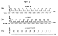
- Fig. 7 illustrates the picture type and the generated code amount in the coding device according to the second embodiment.
- the timing of variation of the code amount by the P frame is different between the picture a and the picture b. Therefore, as shown in Fig. 7(C), the variation of code amount of the multiplexed pictures is not twice but equal to that of 1 channel as in the case of the first embodiment. Consequently, the capacity of the buffer 19 corresponding to 1 picture signal (1 channel) is enough, resulting in a substantial reduction of the picture signal delay.
- the unidirectional prediction coding is performed by a different coder, where Tp is a period of the P frame of a certain picture and N is the number of the picture channels.
Landscapes
- Engineering & Computer Science (AREA)
- Multimedia (AREA)
- Signal Processing (AREA)
- Computing Systems (AREA)
- Theoretical Computer Science (AREA)
- Compression Or Coding Systems Of Tv Signals (AREA)
- Image Processing (AREA)
- Compression, Expansion, Code Conversion, And Decoders (AREA)
Applications Claiming Priority (2)
| Application Number | Priority Date | Filing Date | Title |
|---|---|---|---|
| JP86044/94 | 1994-03-31 | ||
| JP8604494A JP3102260B2 (ja) | 1994-03-31 | 1994-03-31 | 動画像符号化装置 |
Publications (2)
| Publication Number | Publication Date |
|---|---|
| EP0675656A2 true EP0675656A2 (de) | 1995-10-04 |
| EP0675656A3 EP0675656A3 (de) | 1996-02-07 |
Family
ID=13875683
Family Applications (1)
| Application Number | Title | Priority Date | Filing Date |
|---|---|---|---|
| EP19950104583 Withdrawn EP0675656A3 (de) | 1994-03-31 | 1995-03-28 | Bewegtbildkodierungsvorrichtung. |
Country Status (4)
| Country | Link |
|---|---|
| US (1) | US6094224A (de) |
| EP (1) | EP0675656A3 (de) |
| JP (1) | JP3102260B2 (de) |
| KR (1) | KR950028536A (de) |
Cited By (2)
| Publication number | Priority date | Publication date | Assignee | Title |
|---|---|---|---|---|
| EP0732671A3 (de) * | 1995-03-17 | 1997-04-09 | Nec Corp | Videodecodersystem |
| US6954499B2 (en) | 2000-03-15 | 2005-10-11 | Victor Company Of Japan, Ltd | Moving picture coding, coded-moving picture bitstream conversion and coded-moving picture bitstream multiplexing |
Families Citing this family (4)
| Publication number | Priority date | Publication date | Assignee | Title |
|---|---|---|---|---|
| US6359911B1 (en) * | 1998-12-04 | 2002-03-19 | Koninklijke Philips Electronics N.V. (Kpenv) | MPEG-2 transport demultiplexor architecture with non-time-critical post-processing of packet information |
| KR100635010B1 (ko) * | 1999-10-07 | 2006-10-16 | 삼성전자주식회사 | 다수의 부호기를 이용한 영상부호화장치 |
| KR100363733B1 (ko) * | 2000-02-15 | 2002-12-05 | 주식회사 훠엔시스 | 동기신호 우선순위 검출을 이용한 다채널 영상 인코딩시스템 |
| JP4577288B2 (ja) * | 2006-09-27 | 2010-11-10 | ソニー株式会社 | 情報処理装置および方法、プログラム、並びに記録媒体 |
Family Cites Families (19)
| Publication number | Priority date | Publication date | Assignee | Title |
|---|---|---|---|---|
| US4215369A (en) * | 1977-12-20 | 1980-07-29 | Nippon Electric Company, Ltd. | Digital transmission system for television video signals |
| US4455649A (en) * | 1982-01-15 | 1984-06-19 | International Business Machines Corporation | Method and apparatus for efficient statistical multiplexing of voice and data signals |
| JPS58145284A (ja) * | 1982-02-23 | 1983-08-30 | Fujitsu Ltd | 画像信号多重化方式 |
| CA1253255A (en) * | 1983-05-16 | 1989-04-25 | Nec Corporation | System for simultaneously coding and decoding a plurality of signals |
| US4951140A (en) * | 1988-02-22 | 1990-08-21 | Kabushiki Kaisha Toshiba | Image encoding apparatus |
| US5517368A (en) * | 1990-07-06 | 1996-05-14 | Hitachi, Ltd. | Digital transmission signal processing system and recording/reproducing system |
| US5115309A (en) * | 1990-09-10 | 1992-05-19 | At&T Bell Laboratories | Method and apparatus for dynamic channel bandwidth allocation among multiple parallel video coders |
| JP3070110B2 (ja) * | 1991-02-27 | 2000-07-24 | 日本電気株式会社 | 動画像信号の伝送システム |
| US5159447A (en) * | 1991-05-23 | 1992-10-27 | At&T Bell Laboratories | Buffer control for variable bit-rate channel |
| US5317397A (en) * | 1991-05-31 | 1994-05-31 | Kabushiki Kaisha Toshiba | Predictive coding using spatial-temporal filtering and plural motion vectors |
| US5231384A (en) * | 1991-08-26 | 1993-07-27 | General Electric Company | Apparatus for splitting video signal between two channels |
| JP2861518B2 (ja) * | 1991-09-03 | 1999-02-24 | 日本電気株式会社 | 適応多重化方式 |
| JPH0568243A (ja) * | 1991-09-09 | 1993-03-19 | Hitachi Ltd | 可変長符号化制御方式 |
| US5216503A (en) * | 1991-12-24 | 1993-06-01 | General Instrument Corporation | Statistical multiplexer for a multichannel image compression system |
| CA2088082C (en) * | 1992-02-07 | 1999-01-19 | John Hartung | Dynamic bit allocation for three-dimensional subband video coding |
| JPH06165153A (ja) * | 1992-11-18 | 1994-06-10 | Victor Co Of Japan Ltd | 多重符号化装置及び復号化装置 |
| US5481543A (en) * | 1993-03-16 | 1996-01-02 | Sony Corporation | Rational input buffer arrangements for auxiliary information in video and audio signal processing systems |
| BE1007490A3 (nl) * | 1993-09-10 | 1995-07-11 | Philips Electronics Nv | Inrichting voor het overdragen van een pluraliteit van televisie signalen over een transmissie kanaal. |
| US5550590A (en) * | 1994-03-04 | 1996-08-27 | Kokusai Denshin Denwa Kabushiki Kaisha | Bit rate controller for multiplexer of encoded video |
-
1994
- 1994-03-31 JP JP8604494A patent/JP3102260B2/ja not_active Expired - Fee Related
-
1995
- 1995-03-14 KR KR1019950005199A patent/KR950028536A/ko not_active Ceased
- 1995-03-28 EP EP19950104583 patent/EP0675656A3/de not_active Withdrawn
-
1997
- 1997-06-11 US US08/873,256 patent/US6094224A/en not_active Expired - Lifetime
Cited By (4)
| Publication number | Priority date | Publication date | Assignee | Title |
|---|---|---|---|---|
| EP0732671A3 (de) * | 1995-03-17 | 1997-04-09 | Nec Corp | Videodecodersystem |
| US5727091A (en) * | 1995-03-17 | 1998-03-10 | Nec Corporation | Video decoder system |
| US6954499B2 (en) | 2000-03-15 | 2005-10-11 | Victor Company Of Japan, Ltd | Moving picture coding, coded-moving picture bitstream conversion and coded-moving picture bitstream multiplexing |
| US7697607B2 (en) | 2000-03-15 | 2010-04-13 | Victor Company Of Japan, Ltd. | Moving picture coding, coded-moving picture bitstream conversion and coded-moving picture bitstream multiplexing |
Also Published As
| Publication number | Publication date |
|---|---|
| JP3102260B2 (ja) | 2000-10-23 |
| US6094224A (en) | 2000-07-25 |
| EP0675656A3 (de) | 1996-02-07 |
| JPH07274179A (ja) | 1995-10-20 |
| KR950028536A (ko) | 1995-10-18 |
Similar Documents
| Publication | Publication Date | Title |
|---|---|---|
| US5543932A (en) | Digital video signal recording apparatus and digital video signal reproducing apparatus | |
| US5917988A (en) | Editing apparatus, editing method and decoding apparatus for compressed video signal | |
| JP3364281B2 (ja) | 時分割ビデオ及びオーディオ信号の同期方式 | |
| US5440345A (en) | High efficient encoding/decoding system | |
| US6504576B2 (en) | Digital signal coding method and apparatus, signal recording medium, and signal transmission method for recording a moving picture signal and an acoustic signal | |
| US6483945B1 (en) | Moving picture encoding method and apparatus | |
| JP2000059790A (ja) | 動画像符号列変換装置及びその方法 | |
| US6333950B1 (en) | Encoding apparatus and method and computer readable recording medium in which encoding program has been recorded | |
| US6240137B1 (en) | Encoding apparatus and method, decoding apparatus and method, and editing method | |
| US7379497B2 (en) | Encoded data outputting apparatus and method | |
| KR100289856B1 (ko) | 화상 신호 재생 방법 및 화상 신호 재생 장치 | |
| US6094224A (en) | Moving image coding device | |
| EP0632653A2 (de) | Digitaler Videorekorder für Videosignale mit hoher Auflösung mit hoch aufgelöster Anzeige in speziellen Wiedergabebetreibsarten | |
| US6885703B1 (en) | Video code processing method, which can generate continuous moving pictures | |
| US5798804A (en) | Image decoder for decoding variable-length image data using frame synchronizing signal and method of decoding the image data | |
| JPH10190617A (ja) | 映像信号復号化装置 | |
| JP4520062B2 (ja) | 統計的にマルチプレックスされたmpeg転送ストリームのデマルチプレクス方法 | |
| US7006570B2 (en) | Video signal coding method and video signal encoder | |
| US6307594B1 (en) | Method and device for synchronizing coded signals | |
| US6157770A (en) | Moving picture data reproduction controlling system and method for reproducing moving picture data having block elements and minimum elements each with headers | |
| EP0735770B1 (de) | Signalverarbeitungsgerät | |
| JP3594017B2 (ja) | ビットストリームの伝送方法及び伝送システム | |
| JP2819971B2 (ja) | フレーム間予測符号化復号化装置 | |
| JPH0951523A (ja) | ニアビデオオンデマンド受信装置 | |
| JP2003299024A (ja) | 映像情報記録媒体、映像情報記録装置及び記録方法、並びに、映像情報再生装置及び再生方法 |
Legal Events
| Date | Code | Title | Description |
|---|---|---|---|
| PUAI | Public reference made under article 153(3) epc to a published international application that has entered the european phase |
Free format text: ORIGINAL CODE: 0009012 |
|
| AK | Designated contracting states |
Kind code of ref document: A2 Designated state(s): DE FR GB |
|
| PUAL | Search report despatched |
Free format text: ORIGINAL CODE: 0009013 |
|
| AK | Designated contracting states |
Kind code of ref document: A3 Designated state(s): DE FR GB |
|
| 17P | Request for examination filed |
Effective date: 19960802 |
|
| 17Q | First examination report despatched |
Effective date: 19990401 |
|
| STAA | Information on the status of an ep patent application or granted ep patent |
Free format text: STATUS: THE APPLICATION HAS BEEN WITHDRAWN |
|
| 18W | Application withdrawn |
Effective date: 20061229 |