EP0675521A2 - Quecksilberhochdrucklampe - Google Patents
Quecksilberhochdrucklampe Download PDFInfo
- Publication number
- EP0675521A2 EP0675521A2 EP95103687A EP95103687A EP0675521A2 EP 0675521 A2 EP0675521 A2 EP 0675521A2 EP 95103687 A EP95103687 A EP 95103687A EP 95103687 A EP95103687 A EP 95103687A EP 0675521 A2 EP0675521 A2 EP 0675521A2
- Authority
- EP
- European Patent Office
- Prior art keywords
- pressure mercury
- mercury lamp
- ppm
- lamp according
- vanadium
- Prior art date
- Legal status (The legal status is an assumption and is not a legal conclusion. Google has not performed a legal analysis and makes no representation as to the accuracy of the status listed.)
- Withdrawn
Links
Images
Classifications
-
- G—PHYSICS
- G03—PHOTOGRAPHY; CINEMATOGRAPHY; ANALOGOUS TECHNIQUES USING WAVES OTHER THAN OPTICAL WAVES; ELECTROGRAPHY; HOLOGRAPHY
- G03F—PHOTOMECHANICAL PRODUCTION OF TEXTURED OR PATTERNED SURFACES, e.g. FOR PRINTING, FOR PROCESSING OF SEMICONDUCTOR DEVICES; MATERIALS THEREFOR; ORIGINALS THEREFOR; APPARATUS SPECIALLY ADAPTED THEREFOR
- G03F7/00—Photomechanical, e.g. photolithographic, production of textured or patterned surfaces, e.g. printing surfaces; Materials therefor, e.g. comprising photoresists; Apparatus specially adapted therefor
- G03F7/70—Microphotolithographic exposure; Apparatus therefor
- G03F7/70008—Production of exposure light, i.e. light sources
- G03F7/70016—Production of exposure light, i.e. light sources by discharge lamps
-
- H—ELECTRICITY
- H01—ELECTRIC ELEMENTS
- H01J—ELECTRIC DISCHARGE TUBES OR DISCHARGE LAMPS
- H01J61/00—Gas-discharge or vapour-discharge lamps
- H01J61/02—Details
- H01J61/12—Selection of substances for gas fillings; Specified operating pressure or temperature
- H01J61/18—Selection of substances for gas fillings; Specified operating pressure or temperature having a metallic vapour as the principal constituent
- H01J61/20—Selection of substances for gas fillings; Specified operating pressure or temperature having a metallic vapour as the principal constituent mercury vapour
-
- H—ELECTRICITY
- H01—ELECTRIC ELEMENTS
- H01J—ELECTRIC DISCHARGE TUBES OR DISCHARGE LAMPS
- H01J61/00—Gas-discharge or vapour-discharge lamps
- H01J61/02—Details
- H01J61/30—Vessels; Containers
- H01J61/302—Vessels; Containers characterised by the material of the vessel
-
- H—ELECTRICITY
- H01—ELECTRIC ELEMENTS
- H01J—ELECTRIC DISCHARGE TUBES OR DISCHARGE LAMPS
- H01J61/00—Gas-discharge or vapour-discharge lamps
- H01J61/02—Details
- H01J61/38—Devices for influencing the colour or wavelength of the light
- H01J61/40—Devices for influencing the colour or wavelength of the light by light filters; by coloured coatings in or on the envelope
-
- H—ELECTRICITY
- H01—ELECTRIC ELEMENTS
- H01J—ELECTRIC DISCHARGE TUBES OR DISCHARGE LAMPS
- H01J61/00—Gas-discharge or vapour-discharge lamps
- H01J61/82—Lamps with high-pressure unconstricted discharge having a cold pressure > 400 Torr
- H01J61/822—High-pressure mercury lamps
Definitions
- the invention is based on a high-pressure mercury lamp according to the preamble of claim 1.
- Such lamps are preferably used for the exposure of photoresists in the production of semiconductors.
- a fundamental problem of such lamps is the undesired radiation at wavelengths below the useful wavelength, which stress the overall system and should therefore be suppressed if possible.
- the path that is usually taken for this is to introduce an absorption filter into the beam path, see again DE-OS 35 27 855. It is an interference filter or color filter.
- a disadvantage of the former solution is the occurrence of absorption gaps due to secondary maxima of the layer stack, while in the second solution intensity losses have to be accepted.
- the problems that are caused by this undesired short-wave radiation have become increasingly acute.
- the specific problem of the present invention is that usable emission lines ( ⁇ 365 nm) and undesired emission lines below 365 nm are very close together, so that known measures are not sufficient.
- incandescent lamps it is known to use dopants for the bulb glass (made of Vycor or hard glass) to suppress the UV component.
- this is low-intensity continuum radiation that decreases sharply towards short wavelengths.
- vanadium, cerium or molybdenum are used as the doping metal ion in an amount of 300-3000 ppm by weight.
- a glass bulb thickness of 1 mm is used.
- the field of application of this doping is the range below 300 nm.
- these dopings have proven to be unsuitable for the present problem because they already noticeably dampen the useful wavelength of 365 nm.
- Another previously known measure is the use of a Ti02 coating (US Pat. No. 4,985,275). However, this material only absorbs substantially below approx. 240 nm and is therefore at most suitable as an additive because of the large distance from the useful wavelength.
- a flask made of quartz glass is used, to which a small amount of vanadium (as oxide) is added.
- a quantity of 250 ppm (by weight) has proven to be sufficient, based on 1 mm wall thickness. With larger wall thicknesses, the doping content can be reduced accordingly (approximately linearly).
- a preferred upper limit is 200 ppm. Especially with low lamp power, less than 150 ppm is often sufficient. A value of 20 ppm has proven to be a practical lower limit for the effectiveness of the absorption. In general, higher doping should be selected for higher lamp power.
- the absorption behavior at very short wavelengths can be improved by adding the oxides of tin or titanium in a total amount of up to 500 ppm (by weight), based on 1 mm wall thickness.
- both materials can also be used simultaneously.
- At least one of these materials can also be applied to the piston wall as a coating.
- Preferred wall thicknesses of the piston are 1 to 5 mm, in particular 1.5 to 4.0 mm.
- the filling preferably contains 0.5 to 15 mg / cm3 of mercury.
- xenon with a cold filling pressure of between 0.1 and 3.0 bar, preferably below 2.0 bar, has proven itself as the starting gas.
- the electrode spacing for this special lamp is between 2 and 9 mm.
- the operating temperature measured on the outer wall of the piston, reaches values between 400 and 950 o C. It must be taken into account because it is known that the exact position of the absorption edge of the vanadium depends on it. The use of vanadium in a small amount is also possible with other types of discharge lamps in which only part of the UV emission is to be used.
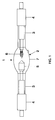
- FIG. 1 schematically shows a high-pressure mercury lamp 1 with a discharge vessel 2, two shaft sections 3 and bases 4 fastened thereon.
- the lamp is operated with a power of 1000 W under direct current.
- the anode 5 and the cathode 6 face each other at a distance of 3 mm.
- the discharge vessel 2 is made of quartz glass with a wall thickness of approximately 2.8 mm, which is doped with vanadium oxide.
- the vanadium content is around 35 ppm.
- the piston is coated with Ti02; the thickness of layer 7 is 1 ⁇ m.
- the flask is filled with 8 mg / cm3 mercury and xenon with a cold filling pressure of 1.7 bar.
- the operating temperature of the piston reaches values of up to 750 o C.
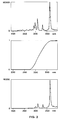
- FIG. 2 shows a section of the lamp spectrum between 200 and 400 nm.
- a lamp spectrum without doping the quartz glass is shown at the top.
- the absorption behavior of the doping according to the invention is shown in the middle.
- the improved lamp spectrum (with doping) is shown below.
- the useful wavelength at 365 nm is actually unattenuated, while the undesired line group is strongly attenuated by 300 nm. If necessary, it can be suppressed even more by adding Sn02.
- Another embodiment is a 3300 W lamp with a mercury filling of 3 mg / cm3 and a xenon cold filling pressure of 0.8 bar.
- the electrode spacing is 6.5 mm.
- the flask is doped with vanadium (50 ppm) and titanium (40 ppm) in the form of their oxides with a wall thickness of 3.7 mm.
- lamps according to the invention allow a considerable reduction in the cost of the overall system, since not only can external filters for the UV range be simplified or omitted entirely, but also the system efficiency, its throughput and also the service life are increased.
- a positive side effect is that the increased absorption in the short-wave UV heats up the bulb. Conversely, this effect can be used to increase the lamp volume without the risk of mercury condensation. This reduces the risk of piston blackening.
Abstract
Description
- Die Erfindung geht aus von einer Quecksilberhochdrucklampe gemäß dem Oberbegriff des Anspruchs 1.
- Derartige Lampen werden bevorzugt für die Belichtung von Fotolacken bei der Herstellung von Halbleitern eingesetzt.
- Bevorzugt wird dabei mit der Quecksilberlinie bei 365 nm gearbeitet (I-Linie), evtl. auch mit der bei 436 nm gelegenen Linie. Einzelheiten des Belichtungsverfahrens und der dabei verwendeten Lampe finden sich in der DE-OS 35 27 855, auf die hiermit ausdrücklich bezug genommen wird.
- Ein grundsätzliches Problem derartiger Lampen ist die unerwünschte Strahlung bei Wellenlängen unterhalb der Nutzwellenlänge, die das Gesamtsystem belasten und daher nach Möglichkeit unterdrückt werden sollen. Der Weg, der üblicherweise dafür eingeschlagen wird, ist das Einbringen eines Absorptionsfilters in den Strahlengang, siehe hierzu wieder DE-OS 35 27 855. Es handelt sich dabei um ein Interferenzfilter oder Farbfilter. Nachteilig an ersterer Lösung ist das Auftreten von Absorptionslücken durch Nebenmaxima des Schichtstapels, während bei der zweiten Lösung Intensitätsverluste in Kauf genommen werden müssen.
Im Zuge der Weiterentwicklung der Belichtungstechnik und der zunehmenden Verwendung leistungsstärkerer Lampen (typisch bis zu 5 kW oder mehr) haben sich die auftretenden Probleme, die durch diese unerwünschte kurzwellige Strahlung hervorgerufen werden, zunehmend verschärft. Neben der größeren thermischen Belastung durch Strahlungsabsorption und den größeren durch die UV-Strahlung hervorgerufenen Strahlungsschäden (Solarisation) im Beleuchtungssystem hat sich insbesondere die Ozonproduktion der Lampen als problematisch erwiesen. Diese setzt chemische Reaktionen in Gang, die zu Belägen auf den optischen Komponenten des Belichtungssystems führen können. Des weiteren treten auch andere UV-induzierte Reaktionen auf, die auf UV-Strahlung des gesamten Wellenlängenbereiches unterhalb 365 nm beruhen. - Es ist Aufgabe der vorliegenden Erfindung, eine gattungsgemäße Lampe bereitzustellen, deren Nutzwellenlängen möglichst ohne Dämpfung zur Verfügung stehen, während die unerwünschte Strahlung bei Wellenlängen unterhalb der Nutzwellenlängen möglichst effektiv unterdrückt werden soll.
- Diese Aufgabe wird durch die kennzeichnenden Merkmale des Anspruches 1 gelöst. Bevorzugte Ausgestaltungen finden sich in den abhängigen Ansprüchen.
- Das spezifische Problem der vorliegenden Erfindung liegt darin, daß nutzbare Emissionslinien (≧ 365 nm) und unerwünschte Emissionslinien unterhalb 365 nm sehr eng beieinander liegen, so daß bekannte Maßnahmen nicht ausreichen.
- Bei Glühlampen ist die Verwendung von Dotierstoffen für das Kolbenglas (aus Vycor oder Hartglas) zur Unterdrückung des UV-Anteils bekannt. Doch handelt es sich hier um Kontinuumstrahlung geringer Intensität, die zu kurzen Wellenlängen hin stark abnimmt. Aus der DE-OS 14 96 072 ist eine Glühlampe bekannt, bei der Vanadium, Cer oder Molybdän als dotierendes Metallion verwendet werden in einer Menge von 300 - 3000 ppm-Gew. Dabei ist eine Glaskolbenstärke von 1 mm angesetzt. Das Einsatzgebiet dieser Dotierung ist der Bereich unter 300 nm. Diese Dotierungen haben sich überraschenderweise deswegen als ungeeignet für das vorliegende Problem erwiesen, weil sie die Nutzwellenlänge von 365 nm bereits merklich dämpfen. Eine weitere vorbekannte Maßnahme ist die Verwendung einer Ti0₂-Beschichtung (US-PS 4 985 275). Dieses Material absorbiert jedoch wesentlich erst unterhalb von ca. 240 nm und ist daher wegen des großen Abstandes zur Nutzwellenlänge allenfalls als Zusatz geeignet.
- Erfindungsgemäß wird ein Kolben aus Quarzglas verwendet, dem eine geringe Menge Vanadium (als Oxid) zugesetzt wird. Dabei hat sich eine Menge von 250 ppm (Gew.) als ausreichend erwiesen, bezogen auf 1 mm Wandstärke. Bei größeren Wandstärken kann der Dotiergehalt entsprechend (in etwa linear) reduziert werden.
- Größere Dotiermengen würden die Nutzwellenlänge bei 365 nm dämpfen und außerdem eine unerwünschte Absorption im sichtbaren Strahlungsbereich bewirken.
- Eine bevorzugte Obergrenze ist 200 ppm. Insbesondere bei Kleiner Lampenleistung sind oft schon weniger als 150 ppm ausreichend. Als praktische Untergrenze für die Wirksamkeit der Absorption hat sich ein Wert von 20 ppm erwiesen. Generell ist bei höherer Lampenleistung eine höhere Dotierung zu wählen.
- Zusätzlich kann das Absorptionsverhalten bei sehr kurzen Wellenlängen (unterhalb ca. 300 bzw. 250 nm) durch Zugabe der Oxide von Zinn bzw. von Titan in einer Gesamtmenge bis zu 500 ppm (Gew.), bezogen auf 1 mm Wandstärke, verbessert werden. Insbesondere können auch beide Materialien gleichzeitig verwendet werden.
- Alternativ kann auch zumindest eines dieser Materialien als Beschichtung auf die Kolbenwand aufgetragen werden.
- Bevorzugte Wandstärken des Kolbens liegen bei 1 bis 5 mm, insbesondere 1,5 bis 4,0 mm.
- Um eine hohe Intensität der Nutzwellenlängen zu erzielen, enthält die Füllung vorzugsweise 0,5 bis 15 mg/cm³ Quecksilber. Außerdem hat sich als Startgas Xenon mit einem Kaltfülldruck, der zwischen 0,1 und 3,0 bar, bevorzugt unter 2,0 bar liegt, bewährt. Der Elektrodenabstand liegt bei dieser Speziallampe zwischen 2 und 9 mm.
- Die Betriebstemperatur, gemessen an der Außenwand des Kolbens, erreicht Werte zwischen 400 und 950oC. Sie muß deshalb berücksichtigt werden, weil bekanntlich die genaue Lage der Absorptionskante des Vanadiums davon abhängt. Die Verwendung von Vanadium in geringer Menge ist auch bei anderen Entladungslampentypen möglich, bei denen nur ein Teil der UV-Emission genutzt werden soll.
- Die Erfindung wird im folgenden anhand zweier Ausführungsbeispiele näher erläutert. Es zeigt
- Figur 1
- eine erfindungsgemäße Quecksilberhochdrücklampe
- Figur 2
- ein Spektrum einer derartigen Lampe.
- In Figur 1 ist schematisch eine Quecksilberhochdrücklampe 1 mit einem Entladungsgefäß 2, zwei Schaftabschnitten 3 und jeweils daran befestigten Sockeln 4 gezeigt. Die Lampe wird mit einer Leistung von 1000 W unter Gleichstrom betrieben. Die Anode 5 und die Kathode 6 stehen sich in einem Abstand von 3 mm gegenüber. Das Entladungsgefäß 2 ist aus Quarzglas mit einer Wandstärke von ca. 2,8 mm gefertigt, das mit Vanadiumoxid dotiert ist. Der Vanadiumanteil liegt bei etwa 35 ppm. Zusätzlich ist der Kolben mit Ti0₂ beschichtet; die Dicke der Schicht 7 beträgt 1 µm. Der Kolben ist mit 8 mg/cm³ Quecksilber und Xenon mit einem Kaltfülldrück von 1,7 bar gefüllt. Die Betriebstemperatur des Kolbens erreicht außen Werte bis zu 750oC.
- Einen Ausschnitt aus dem Lampenspektrum zwischen 200 und 400 nm zeigt Figur 2. Oben ist ein Lampenspektrum ohne Dotierung des Quarzglases gezeigt. In der Mitte ist das Absorptionsverhalten der erfindungsgemäßen Dotierung dargestellt. Unten ist das verbesserte Lampenspektrum (mit Dotierung) gezeigt.
- Man erkennt, daß die Nutzwellenlänge bei 365 nm tatsächlich ungeschwächt ist, während die unerwünschte Liniengruppe um 300 nm stark gedämpft ist. Sie kann ggf. durch Zusatz von Sn0₂ noch stärker unterdrückt werden.
- Ein weiteres Ausführungsbeispiel ist eine 3300 W-Lampe mit einer Hg-Füllung von 3 mg/cm³ und einem Xenon-Kaltfülldrück von 0,8 bar. Der Elektrodenabstand beträgt 6,5 mm. Der Kolben ist bei einer Wandstärke von 3,7 mm mit Vanadium (50 ppm) und Titan (40 ppm) in Form ihrer Oxide dotiert.
- Diese erfindungsgemäßen Lampen gestatten eine erhebliche Reduktion der Kosten des Gesamtsystems, da nicht nur externe Sperrfilter für den UV-Bereich vereinfacht oder ganz weggelassen werden können, sondern sich auch der Systemwirkungsgrad, dessen Durchsatz und auch Lebensdauer erhöht. Ein positiver Nebeneffekt ist, daß die vermehrte Absorption im kurzwelligen UV den Kolben aufheizt. Dieser Effekt kann umgekehrt dazu benutzt werden, das Lampenvolumen zu vergrößern, ohne daß die Gefahr der Hg-Kondensation auftritt. Dadurch wird die Gefahr der Kolbenschwärzung vermindert.
Claims (9)
- Quecksilberhochdrücklampe mit einem Entladungsgefäß aus Quarzglas, das zwei Elektroden und eine Füllung enthält, die Quecksilber und Xenon umfaßt, dadurch gekennzeichnet, daß die Füllung darauf abgestimmt ist, im Bereich von Nutzwellenlängen, die durch Quecksilber erzeugt werden und zumindest die Resonanzlinie bei ca. 365 nm umfassen, zu emittieren, wobei gleichzeitig zur Absorption von Wellenlängen unterhalb von 365 nm das Quarzglas, bezogen auf 1 mm Wandstärke, Vanadium als Metallion eines Dotierstoffes in einer Menge von weniger als 250 ppm (Gew.) enthält, und wobei die äußere Wandtemperatur des Entladungsgefäßes zwischen 400 und 950oC beträgt.
- Quecksilberhochdrücklampe nach Anspruch 1, dadurch gekennzeichnet, daß der Vanadiumanteil kleiner als 200 ppm ist.
- Quecksilberhochdrücklampe nach Anspruch 2, dadurch gekennzeichnet, daß der Vanadiumanteil zwischen 20 und 150 ppm liegt.
- Quecksilberhochdrücklampe nach einem der vorhergehenden Ansprüche, dadurch gekennzeichnet, daß das Quarzglas zusätzlich Titan und/oder Zinn als Metallion eines Dotierstoffs in einer Gesamtmenge bis zu 500 ppm (Gew.) enthält.
- Quecksilberhochdrücklampe nach einem der vorhergehenden Ansprüche, dadurch gekennzeichnet, daß das Quarzglas mit Ti0₂ oder Sn0₂ beschichtet ist.
- Quecksilberhochdrücklampe nach einem der vorhergehenden Ansprüche, dadurch gekennzeichnet, daß die Wandstärke des Entladungsgefäßes zwischen 1 und 5 mm beträgt.
- Quecksilberhochdrücklampe nach einem der vorhergehenden Ansprüche, dadurch gekennzeichnet, daß die Füllung Quecksilber in einer Menge zwischen 0,5 und 15 mg/cm³ sowie Xenon mit einem Kaltfülldrück von 0,1 bis 2,5 bar umfaßt.
- Quecksilberhochdrucklampe nach Anspruch 1, dadurch gekennzeichnet, daß der Elektrodenabstand zwischen 2 und 9 mm beträgt
- Verwendung einer Lampe gemäß einer der vorhergehenden Ansprüche für die Belichtung von Fotolacken bei der Herstellung von Halbleitern.
Applications Claiming Priority (2)
| Application Number | Priority Date | Filing Date | Title |
|---|---|---|---|
| DE4410968A DE4410968A1 (de) | 1994-03-29 | 1994-03-29 | Quecksilberhochdrucklampe |
| DE4410968 | 1994-03-29 |
Publications (2)
| Publication Number | Publication Date |
|---|---|
| EP0675521A2 true EP0675521A2 (de) | 1995-10-04 |
| EP0675521A3 EP0675521A3 (de) | 1997-04-16 |
Family
ID=6514198
Family Applications (1)
| Application Number | Title | Priority Date | Filing Date |
|---|---|---|---|
| EP95103687A Withdrawn EP0675521A3 (de) | 1994-03-29 | 1995-03-14 | Quecksilberhochdrucklampe. |
Country Status (4)
| Country | Link |
|---|---|
| US (1) | US5650630A (de) |
| EP (1) | EP0675521A3 (de) |
| JP (1) | JP3016061U (de) |
| DE (1) | DE4410968A1 (de) |
Cited By (1)
| Publication number | Priority date | Publication date | Assignee | Title |
|---|---|---|---|---|
| EP0704881A3 (de) * | 1994-09-27 | 1998-09-23 | Ushiodenki Kabushiki Kaisha | Entladungslampe |
Families Citing this family (4)
| Publication number | Priority date | Publication date | Assignee | Title |
|---|---|---|---|---|
| US5751896A (en) * | 1996-02-22 | 1998-05-12 | Micron Technology, Inc. | Method and apparatus to compensate for non-uniform film growth during chemical vapor deposition |
| JP2000123786A (ja) * | 1998-10-13 | 2000-04-28 | Matsushita Electronics Industry Corp | 高圧水銀ランプ、この高圧水銀ランプを用いた照明光学装置、およびこの照明光学装置を用いた画像表示装置 |
| CZ20012114A3 (cs) | 1998-12-16 | 2002-02-13 | Nienburger Glas Gmbh | Sklo absorbující ultrafialové světlo, způsob jeho přípravy a pouľití |
| DE19905108A1 (de) * | 1998-12-16 | 2000-06-21 | Nienburger Glas Gmbh | Ultraviolettes Licht absorbierendes Glas, Verfahren zur Herstellung und Verwendung desselben |
Citations (6)
| Publication number | Priority date | Publication date | Assignee | Title |
|---|---|---|---|---|
| FR1350354A (fr) * | 1962-03-15 | 1964-01-24 | Corning Glass Works | Lampe électrique |
| US3848152A (en) * | 1972-06-06 | 1974-11-12 | Corning Glass Works | Electric lamp having a fused silica glass envelope |
| GB2171214A (en) * | 1985-02-19 | 1986-08-20 | Ushio Electric Inc | Projection printing |
| GB2191888A (en) * | 1986-06-05 | 1987-12-23 | Ushio Electric Inc | Fused silica envelope for discharge lamp |
| JPH04368768A (ja) * | 1991-06-17 | 1992-12-21 | Matsushita Electric Ind Co Ltd | メタルハライドランプ |
| JPH0672738A (ja) * | 1991-09-06 | 1994-03-15 | Toshiba Glass Co Ltd | Hidランプ用ガラス |
Family Cites Families (4)
| Publication number | Priority date | Publication date | Assignee | Title |
|---|---|---|---|---|
| US2862131A (en) * | 1951-02-27 | 1958-11-25 | Saint Gobain | Glass for glow discharge lamps such as fluorescent luminescent lamps and the like |
| GB1456242A (en) * | 1973-01-19 | 1976-11-24 | Thorn Lighting Ltd | Incandescent lamp |
| USRE30165E (en) * | 1973-01-19 | 1979-12-11 | Thorn Lighting Limited | Electric discharge lamp |
| US4985275A (en) * | 1986-06-05 | 1991-01-15 | Ushio Denki Kabushiki Kaisha | Method for producing a fused silica envelope for discharge lamp |
-
1994
- 1994-03-29 DE DE4410968A patent/DE4410968A1/de not_active Withdrawn
-
1995
- 1995-03-14 EP EP95103687A patent/EP0675521A3/de not_active Withdrawn
- 1995-03-22 JP JP1995003307U patent/JP3016061U/ja not_active Expired - Lifetime
- 1995-03-27 US US08/410,724 patent/US5650630A/en not_active Expired - Fee Related
Patent Citations (6)
| Publication number | Priority date | Publication date | Assignee | Title |
|---|---|---|---|---|
| FR1350354A (fr) * | 1962-03-15 | 1964-01-24 | Corning Glass Works | Lampe électrique |
| US3848152A (en) * | 1972-06-06 | 1974-11-12 | Corning Glass Works | Electric lamp having a fused silica glass envelope |
| GB2171214A (en) * | 1985-02-19 | 1986-08-20 | Ushio Electric Inc | Projection printing |
| GB2191888A (en) * | 1986-06-05 | 1987-12-23 | Ushio Electric Inc | Fused silica envelope for discharge lamp |
| JPH04368768A (ja) * | 1991-06-17 | 1992-12-21 | Matsushita Electric Ind Co Ltd | メタルハライドランプ |
| JPH0672738A (ja) * | 1991-09-06 | 1994-03-15 | Toshiba Glass Co Ltd | Hidランプ用ガラス |
Non-Patent Citations (3)
| Title |
|---|
| DATABASE INSPEC INSTITUTE OF ELECTRICAL ENGINEERS, STEVENAGE, GB Inspec No. 3587757, WENTWORTH W E ET AL: "Evaluation of photo contribution to a chemical reaction using concentrated solar energy" XP002025423 & SOLAR ENERGY, 1990, USA, Bd. 44, Nr. 1, ISSN 0038-092X, Seiten 37-42, * |
| PATENT ABSTRACTS OF JAPAN vol. 017, no. 245 (E-1365), 17.Mai 1993 & JP 04 368768 A (MATSUSHITA ELECTRIC IND CO LTD), 21.Dezember 1992, * |
| PATENT ABSTRACTS OF JAPAN vol. 018, no. 322 (C-1214), 20.Juni 1994 & JP 06 072738 A (TOSHIBA GLASS CO LTD), 15.März 1994, * |
Cited By (1)
| Publication number | Priority date | Publication date | Assignee | Title |
|---|---|---|---|---|
| EP0704881A3 (de) * | 1994-09-27 | 1998-09-23 | Ushiodenki Kabushiki Kaisha | Entladungslampe |
Also Published As
| Publication number | Publication date |
|---|---|
| US5650630A (en) | 1997-07-22 |
| DE4410968A1 (de) | 1995-10-05 |
| EP0675521A3 (de) | 1997-04-16 |
| JP3016061U (ja) | 1995-09-26 |
Similar Documents
| Publication | Publication Date | Title |
|---|---|---|
| EP0588284B1 (de) | Metallhalogenid-Entladungslampe | |
| EP0338637B1 (de) | Hochdruck-Quecksilberdampfentladungslampe | |
| EP1048620B1 (de) | Vorrichtung zur Desinfektion von Wasser mit einer UV-C-Gasentladungslampe | |
| EP2128888B1 (de) | Quecksilberfreie Metallhalogenid-Hochdruckentladungslampe | |
| EP0706201A2 (de) | Quecksilberdampf-Kurzbogenlampe | |
| DE69922485T2 (de) | Niederdruckquecksilberdampfentladungslampe | |
| DE10291427B4 (de) | Halogen-Metalldampflampe für einen Kraftfahrzeugscheinwerfer | |
| DE3336421A1 (de) | Kolbenlampe fuer den fernen uv-bereich | |
| EP1417720B1 (de) | Strahlungsemittierender chip und strahlungsemittierendes bauelement | |
| EP1447615B1 (de) | Gepulster Sonnensimulator mit verbesserter Homogenität | |
| DE2845890C3 (de) | Quecksilber-Edelgas-Entladungslampe | |
| DE69911539T2 (de) | Elektrische Lampe mit Interferenzfilter | |
| EP0675521A2 (de) | Quecksilberhochdrucklampe | |
| DE69921901T2 (de) | Cermet und keramische Entladungslampe | |
| DE10204691C1 (de) | Quecksilberfreie Hochdruckgasentladungslampe und Beleuchtungseinheit mit einer solchen Hochdruckgasentladungslampe | |
| DE69926706T2 (de) | Niederdruckquecksilberdampfeentladungslampe | |
| DD289850A5 (de) | Gefaerbte elektrische lampe | |
| DE10356762B4 (de) | Entladungslampe vom Kurzbogentyp | |
| DE3024438A1 (de) | Niederdruckquecksilberdampfentladungslampe | |
| DE4036122A1 (de) | Koronaentladungs-lichtquellenzelle | |
| EP0628987A2 (de) | Metallhalogenidentladungslampe und Verfahren zu ihrer Herstellung | |
| DE69825482T2 (de) | Deuterium-gasenladungsröhre | |
| DE4203345A1 (de) | Hochleistungsstrahler | |
| EP2981984B1 (de) | Leuchte | |
| DE60016557T2 (de) | Metallhalogenidlampe |
Legal Events
| Date | Code | Title | Description |
|---|---|---|---|
| PUAI | Public reference made under article 153(3) epc to a published international application that has entered the european phase |
Free format text: ORIGINAL CODE: 0009012 |
|
| AK | Designated contracting states |
Kind code of ref document: A2 Designated state(s): BE DE FR GB IT NL |
|
| PUAL | Search report despatched |
Free format text: ORIGINAL CODE: 0009013 |
|
| AK | Designated contracting states |
Kind code of ref document: A3 Designated state(s): BE DE FR GB IT NL |
|
| 17P | Request for examination filed |
Effective date: 19970505 |
|
| 17Q | First examination report despatched |
Effective date: 19971211 |
|
| STAA | Information on the status of an ep patent application or granted ep patent |
Free format text: STATUS: THE APPLICATION IS DEEMED TO BE WITHDRAWN |
|
| 18D | Application deemed to be withdrawn |
Effective date: 19980422 |