EP0675263A1 - Système de collecteur pour la poussière dans des tunnels - Google Patents
Système de collecteur pour la poussière dans des tunnels Download PDFInfo
- Publication number
- EP0675263A1 EP0675263A1 EP95107725A EP95107725A EP0675263A1 EP 0675263 A1 EP0675263 A1 EP 0675263A1 EP 95107725 A EP95107725 A EP 95107725A EP 95107725 A EP95107725 A EP 95107725A EP 0675263 A1 EP0675263 A1 EP 0675263A1
- Authority
- EP
- European Patent Office
- Prior art keywords
- air
- dust collecting
- tunnel
- dust
- collecting chamber
- Prior art date
- Legal status (The legal status is an assumption and is not a legal conclusion. Google has not performed a legal analysis and makes no representation as to the accuracy of the status listed.)
- Granted
Links
Images


Classifications
-
- E—FIXED CONSTRUCTIONS
- E21—EARTH DRILLING; MINING
- E21F—SAFETY DEVICES, TRANSPORT, FILLING-UP, RESCUE, VENTILATION, OR DRAINING IN OR OF MINES OR TUNNELS
- E21F1/00—Ventilation of mines or tunnels; Distribution of ventilating currents
- E21F1/003—Ventilation of traffic tunnels
-
- E—FIXED CONSTRUCTIONS
- E21—EARTH DRILLING; MINING
- E21F—SAFETY DEVICES, TRANSPORT, FILLING-UP, RESCUE, VENTILATION, OR DRAINING IN OR OF MINES OR TUNNELS
- E21F5/00—Means or methods for preventing, binding, depositing, or removing dust; Preventing explosions or fires
- E21F5/20—Drawing-off or depositing dust
Definitions
- This invention relates to a tunnel dust collecting system in which an electrical dust collector is used to remove dust and smoke from the contaminated air in a tunnel thereby to use the air again, and more particularly to a tunnel dust collecting system which is installed on the ceiling of a tunnel which is provided mainly for automobiles.
- Fig. 8(A) a tunnel dust collecting system of bypass tunnel type as shown in Fig. 8(A)
- a tunnel dust collecting system of ceiling installation type as shown in Fig. 8(B)
- Figs. 9(A) and 9(B) are a plan view and a sectional view of the tunnel dust collecting system shown in Fig. 8(B).
- a bypass tunnel is connected, as a dust collecting chamber 2, to the main tunnel 1 provided for automobiles, so that the air contaminated in the tunnel 1 is led into the dust collecting chamber at one end opened in the side wall of the main tunnel 1, where it is decontaminated with an electrical dust collector 3 (hereinafter referred to merely as "a dust collector 3", when applicable).
- the air thus processed is supplied into the main tunnel 1 with an air blower 4 through the other end of the dust collecting chamber 2.
- a ceiling board 5 is installed in such a manner as to form a dust collecting chamber 2 in the upper portion of a tunnel.
- the dust collecting chamber 2 has one end 2a which is used to suck air from the tunnel (hereinafter referred to as "an air sucking end 2a”, when applicable), and the other end 2b which is used to supply decontaminated air into the tunnel (hereinafter referred to as "an air supplying end 2b", when applicable).
- the contaminated air sucked into the dust collecting chamber 2 through the air sucking end 2a is decontaminated with dust collectors 3, and the air thus decontaminated is supplied into the tunnel with air blowers 4 provided near the air supplying end 2b.
- the tunnel dust collecting system of ceiling installation type is advantageous in that its installation cost is lower because it is unnecessary to form the bypass tunnel.
- two dust collectors 3 are provided in the dust collecting chamber 2 in such a manner that they are separated from each other with a partition board 6. More specifically, the dust collecting chamber is divided by the partition board 6 into two parts,in which the two dust collectors are provided, respectively.
- Two axial flow type air blowers 4 with cylindrical casings 4b are provided at the air supplying end 2b of the dust collecting chamber 2, and air sucking inlets 7 are provided at the air sucking end of the dust collecting chamber 2.
- the air in the upper portion of the tunnel is sucked through the air sucking inlets 7 linearly along the central axis of the tunnel into the dust collecting chamber and decontaminated with the dust collectors 3, and the air thus decontaminated is linearly supplied into the tunnel with the air blowers 4 through air supplying outlets 4a.
- the ceiling board 5 serves as a base board which supports the dust collectors 3 etc. Generally, the ceiling board 5 is extended to the air supplying outlets 4a of the air blowers 4, being utilized as means for making access to the air blowers for inspection or maintenance.
- the air sucking end 2a of the dust collecting chamber 2 is employed as the air sucking inlets 7.
- a tunnel dust collecting system of ceiling installation type in which, as shown in Fig. 10, the end of the dust collecting chamber corresponding to the above-described air sucking end is closed, and instead an air sucking inlet is opened in the end portion of the ceiling board 5 (hereinafter referred to as "a tunnel dust collecting system of upward suction type", when applicable).
- the air sucking end 2a of the dust collecting chamber 2 defined by the ceiling board 5 is closed with a closing board 8, and instead a rectangular-window-shaped air sucking inlet 9 is formed in the ceiling board 5 near the closing board 8.
- the contaminated air in the tunnel is led through the air sucking inlet 9 into the dust collecting chamber as indicated by the arrows, and decontaminated with the dust collectors 3.
- the air thus decontaminated is supplied into the tunnel with the air blowers 4.
- the above-described conventional tunnel dust collecting system of ceiling installation type is disadvantageous in the following points lowering its dust collection efficiency.
- the conventional tunnel dust collecting system as shown in Fig. 9, the air decontaminated by the dust collectors 3 is blown along the central axis of the tunnel 1 into the upper portion of the latter as it is. Therefore, when compared with the tunnel dust collecting system of bypass tunnel type, the decontaminated air is difficult to mix with the contaminated air in the driveway space 1a of the tunnel 1.
- the conventional system cannot decontaminate air sufficiently in the area where the engine load of an automobile is increased to increase the contamination of air as in an up- grade driveway of an undersea tunnel.
- the interval of installation of dust collecting systems is determined with the distance taken into consideration with which decontaminated air is completely mixed with contaminated air.
- the ceiling board 5 is provided below the air blowers 4. Therefore, as shown in Fig. 9(B), the stream of air blown by the air blowers 4 is not smoothly met with the stream of air around it, thus forming eddies 12. As a result, energy loss is caused, and accordingly it is necessary to use high electric power to supply decontaminated air at a predetermined flow rate.
- the air sucking inlet 9 is formed in the ceiling board 5 in such a manner that its edges are perpendicular to the ceiling board. Therefore, as shown in Fig. 11, the air sucked into the dust collecting chamber 2 forms a contraction flow; that is, the air sucked into the dust collecting chamber tends to concentrate at the center of the dust collector 3 leaving the front and rear edges 9a an 9b of the air sucking inlet 9. As a result, only 85 to 90% of the capacity of the dust collector is used, and the pressure loss at the air sucking inlet 9 is as high as 5 to 10%.
- a general object of this invention is to provide a tunnel dust collecting system in which these difficulties are eliminated, thereby to improve the cleanliness of the air in a tunnel. This will be described in more detail.
- a first object of this invention is to provide a tunnel dust collecting system with which the distance required for mixing decontaminated air with contaminated air is decreased, so that the number of dust collecting systems per unitary length of a tunnel is increased, whereby the air decontamination degree in the tunnel is improved.
- a second object of the invention is to provide a tunnel dust collecting system in which the above-described streams of air smoothly meet one another at the outlets of the air blowers whereby electric power is economically used.
- a third object of the invention is to provide a tunnel dust collecting system in which dust collectors are suitably arranged to increase the flow rate of decontaminated air per station.
- a fourth object of the invention is to provide a tunnel dust collecting system of upward suction type which is high in dust collection efficiency being free from the above-described difficulties the stream of air sucked in the dust collecting chamber is concentrated, with pressure loss.
- a tunnel dust collecting system comprising: a dust collecting chamber formed in the upper space of a tunnel with a ceiling board in such a manner that the dust collecting chamber has one end serving as an air sucking end and the other end serving as an air supplying end; electric dust collectors arranged in the dust collecting chamber, and air blowers in the dust collecting chamber at the air supplying end; according to a first aspect of the invention, a nozzle is connected to the air outlet of each of the air blowers in such a manner that air decontaminated is blown slightly downwardly outwardly with respect to the central axis of the tunnel, thus achieving the first object of the invention.
- the air blowing direction forms an cubical angle of 5 to 12° with the central axis of the tunnel.
- the ceiling board is extended to the air blowers, so that the casings of the air blowers are exposed in the lower space of the tunnel, thus achieving the second object of the invention.
- a ventilated scaffold may be installed below the air blowers to make access to the latter for maintenance.
- the dust collectors are, in general, arranged in parallel with the longitudinal direction of the tunnel so as to lead the air stream straightly to the air sucking surfaces of the dust collectors.
- the tunnel dust collecting system according to a third aspect of the invention, all of the dust collectors except the first one as viewed from the air sucking end of the dust collecting chamber are set obliquely with respect to the longitudinal direction of the dust collecting chamber as if partially overlapped one another when viewed from the air sucking end, thus achieving the third object of the invention.
- the first dust collector in order to uniformly distribute the air stream to the dust collector, it is preferable that the first dust collector is smaller in air stream projection area than those of the remaining, and the distance between the first and second dust collectors is longer than those between the second and third dust collectors, between the third and fourth dust collectors, and so forth.
- each electric dust collector has outlet dampers, the degrees of opening of which are adjusted to control the flow rate of air therein.
- the air sucking inlet formed in the ceiling board has a first wall upstream thereof the upper and lower edges of which are rounded continuously with a first radius R1 and a second radius R2 smaller than the first radius, respectively, and a second wall downstream thereof the upper and lower edges of which are rounded continuously with the second and first radii, respectively.
- R1 t to 3t
- R2 t/5 to t/3 , where t is the thickness of the ceiling board.
- the decontaminated air blowing direction of the air blowers are set slightly downwardly outwardly with respect to the central axis of the tunnel so as to form spiral air streams in the tunnel thereby to quickly mix the decontaminated air with the contaminated air in the tunnel.
- the ceiling board is extended only to the air blowers; that is, no ceiling board is provided below the air blowers, so that the air streams outputted by the air blowers are made in parallel with external air streams around them; that is, the former meet the latter smoothly, thereby preventing formation of eddies.
- a ventilated scaffold made of metal net, perforated steel plate or metal grid can be installed below them.
- the effective air flow area for the dust collectors is increased when compared with the air flow area provided for the dust collecting chamber.
- the dust collectors are positioned as if they were partially overlapped with one another when viewed from the air sucking end of the dust collecting chamber, then the air stream to a dust collector is disturbed by the preceding dust collector.
- the dust collectors form an excessively large angle with the longitudinal direction of the dust collecting, then the contaminated air is not uniformly distributed to the dust collectors.
- the angle is not more than 12°, and the distance between adjacent dust collectors is at least twice the width of the dust collector, then the contaminated air is uniformly distributed to the dust collectors.
- the air flow area occupied by the first dust collector as viewed from the air sucking end of the dust collecting chamber is large when compared with the whole air flow area of the dust collecting chamber, so that the first dust collector adversely affects the flow rate of air in the second dust collector, at worst that in the third dust collector or in the fourth dust collector.
- the first dust collector is made smaller in air stream projection area than the others, and the distance between the first and second dust collectors is made longer than the distance between the second and third dust collector, the distance between the third and fourth dust collectors, and so forth.
- the distance between the first and second dust collectors is least 1.5 times the diameter of the air stream in the dust collecting chamber at the air sucking end.
- the flow rate of air in each dust collector is controlled by adjusting the degrees of opening of dampers provided at the air outlet.
- the degrees of opening of the dampers of a dust collector are decreased, the flow rate of air in the dust collector is decreased, and the air stream is distributed to the other dust collectors as much.
- the same dampers are provided at the air inlet of each dust collector. However, if the dampers at the air inlet are adjusted, then the air stream flowing through the electrode boards is deflected, so that the dust collection efficiency is lowered.
- preferably only the degrees of opening of the outlet dampers are controlled.
- the air sucking inlet formed in the ceiling board has a first wall upstream thereof and a second wall downstream thereof whose upper and lower edges are continuously rounded with two different radii in such a manner that the first and second walls are inclined in the direction of air stream.
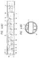
- a first embodiment of the invention a tunnel dust collecting system, will be described with reference to Figs. 1(A) through 1(C).
- a ceiling board 5 having a predetermined length is installed in a tunnel 1 to form a dust collecting chamber 2 in the upper portion of the tunnel.
- the left end of the dust collecting chamber 2 is an air sucking end 2a
- the right end is an air supplying end 2b.
- Two dust collectors 3 are arranged along the right and left side walls of the dust collecting chamber 2, respectively, in such a manner that they are positioned staggered in the dust collecting chamber 2, or they are arranged as if overlapped as viewed from the air sucking end of the dust collecting chamber.
- the dust collecting chamber 2 is separated into two right and left air flow chambers with a partition wall 6 extended along the central axis of the dust collecting chamber 2 in such a manner that the right and left air flow chambers have the two dust collectors 3, respectively.
- Two axial-flow type air blowers 4 are connected to the right and left air flow chambers at the air supplying end.
- Each of the air blowers 4 comprises a cylindrical casing, and an impeller and a drive motor which are built in the casing.
- Each of the air blowers 4 has an air supplying outlet 4a with a nozzle 13 for determining its air blowing direction. The nozzles 13 are directed slightly downwardly outwardly with respect to the central axis of the tunnel 1.
- the contaminated air in the driveway space 1a in the tunnel 1 is led into the dust collecting chamber 2 through the air sucking inlets 7 at the air sucking end 2a.
- the contaminated air thus led is decontaminated with the dust collectors 3.
- the air thus decontaminated is supplied into the driveway space 1a through the nozzles 13 of the air blowers 4.
- the decontaminated air blown through the nozzles 13 forms a pair of spiral air streams in the driveway space 1a as indicated by the broken lines in Fig. 1.
- the decontaminated air supplied through the nozzles mixes with the contaminated air in the driveway space 1a in a short time while winding the latter. It has been confirmed through experiments that the distance required for the decontaminated air to mixed with the contaminated air in the driveway space is shorter about 10% than in the conventional tunnel dust collecting system.
- the technical concept of the invention can be applied to an air blower (jet fan) 4 arranged in a dust collecting system in order to accelerate the mixing of decontaminated air with contaminated air. That is, the air blow 4 is provided with a nozzle 12 so that the air is blown downwardly outwardly. As a result, the air thus blown forms a spiral air stream as indicated by the broken line, with the result that the air mixing efficiency is improved as much, and accordingly a jet fan 4 may be employed which is smaller in capacity.
- jet fan 4 jet fan
- the decontaminated air supplied by the air blowers 4 forms spiral air streams in the driveway space 1a of the tunnel 1.
- the mixing of decontaminated air with contaminated air is accelerated, and the interval of installation of dust collecting systems can be reduced to about 100 m to 90 m.
- FIGs. 3(A) and 3(B) are a plan view and a side view showing a dust collecting chamber in the dust collecting system.
- a ceiling board 5 defining the dust collecting chamber 2 is terminated at two air blowers 4, and the cylindrical casings 4b of the air blowers are exposed downwardly.
- air streams 11 around the air streams 11 come close to the latter in such a manner that the former is substantially in parallel with the latter, so that the former and the latter smoothly meet each other without forming eddies.
- the energy loss attributing to the mixing of the two air streams 10 and 11 is much less than in the conventional tunnel dust collecting system.
- a ventilated scaffold 14 made of metal net for instance may be installed below the air blowers 4. With the scaffold, the air stream 11 from below is not obstructed.
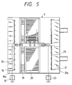
- Figs. 4 and 5 shows a third embodiment of the invention.
- six dust collectors 3A through 3F are provided in the dust collecting chamber 2 in such a manner that they are arranged longitudinally of the dust collecting chamber 2 and shifted from one another laterally of the dust collecting chamber (from one side wall (left side wall) of the dust collecting chamber towards the other side wall (right side wall)) in the stated order.
- Partition boards 15 are extended between the dust collectors 3A through 3F.
- the top dust collector 3A is connected through a partition board 16 to the one side wall of the dust collecting chamber 2, and similarly the last dust collector 3F is connected through another partition board 16 to the other side wall of the dust collecting chamber 2.
- partition boards 15 and 16 are to separate the contaminated air to be processed by the dust collectors 3A through 3F from the air decontaminated by the latter.
- a guide board 17 is connected between the last dust collector 3F and to the other side wall of the dust collecting chamber 2, so as to lead the contaminated air to the dust collector 3F.
- the first dust collector 3F closest to the air sucking end 2a of the dust collecting chamber 2 is smaller in the area of projection to air stream than the others and is set in parallel with the longitudinal direction (right-to-left direction in Fig. 4(A) of the dust collecting chamber.
- the remaining dust collectors 3B through 3F are arranged in such a manner that they form angles (described later) with the longitudinal direction of the dust collecting chamber 2, and they are partly overlapped one another as viewed from the end of the dust collecting chamber 2.
- the dust collectors 3B through 3E form an inclination angle ( ⁇ ) of 10°, and only last dust collector 3F 5°.
- the partition board 15 between the first and second dust collectors 3A and 3B includes a part S which is in parallel with the central axis of the dust collecting chamber 2, so that the distance D between the first and second dust collectors 3A and 3B is longer than the distance d between the second and third dust collectors 3B and 3C, the third and fourth dust collectors 3C and 3D, and so forth.
- the contaminated air in the tunnel is led into the dust collecting chamber through an air sucking inlet 7 at the air sucking end 2a.
- the contaminated air thus led is distributed uniformly to the dust collectors 3 as indicated by the solid line arrows, where it is decontaminated.
- the decontaminated air outputted by the dust collectors 3 is supplied into the driveway space 1a by the air blowers 4 as indicated by the broken line arrows.
- the effective air flow area is the sum of the areas of the air inlets of the dust collectors 3, and it is larger about 20% than that in the conventional dust collecting system, because the dust collectors 3 are arranged as if overlapped as was described before; that is, the flow rate of air processed per station is increased as much. Furthermore, since the second to last dust collectors 3B through 3F are so arranged as to form angles with the central axis of the dust collecting chamber as was described before, the contaminated air is distributed along the partition boards 15 substantially uniformly to the dust collectors 3B through 3F although the latter are arranged as if overlapped as viewed from the end of the dust collecting chamber.
- the area occupied by the first dust collector 3A in the air flow path in the dust collecting chamber 2 is larger than those occupied by the other dust collectors. Therefore, if the first dust collector 3A is equal in the area of projection to air stream to the remaining dust collectors 3B through 3F, then as shown in Fig. 6 contraction flows occur, as a result of which the air stream leaves the partition board 15 to flow over the second dust collector 3B to the third dust collector 3C.
- This difficulty is eliminated as follows: A relatively small dust collector is employed as the first dust collector 3A to suppress the possibility of occurrence of contraction flows.
- the distance D is increased so that the air stream flows to the second dust collector 3B. It has been confirmed through experiments that the distance D should be at least 1.5 times the diameter of the air stream at the air sucking end 2a of the dust collecting.
- the distribution of air stream to the dust collectors 3 may be precisely controlled by adjusting the degrees of opening of the outlet dampers of the dust collectors 3 as described below.
- Fig. 5 is a sectional plan view showing the arrangement of each of the dust collectors 3.
- the dust collector 3 comprises: inlet dampers 18; a charging section 19; a dust collecting section 20; and outlet dampers 21.
- the particles such as dust and smoke particles in the contaminated air led into the dust collector 3 through the inlet dampers 18 are charged by the charging section 19, so that they are caught by the dust collecting section 20 to which high voltage is applied by a high voltage generator 22; that is, the air is decontaminated.
- the air thus decontaminated is allowed to flow out of the dust collector through the outlet dampers 19.
- compressed air is jetted to remove them therefrom.
- the inlet dampers 18 and the outlet dampers 21 are mounted on vertical shafts 18a and 21a, respectively, and are turned to open and close the air inlet and the air outlet of the dust collector.
- the degrees of opening of the dampers 18 and 21 are decreased, the resistance of the dust collector to the air stream is increased, so that the flow rate of air stream is decreased, and accordingly the air stream is distributed to the other dust collectors as much as the flow rate of air stream has been decreased in the above-described manner.
- the degrees of opening of the outlet dampers 21 are so adjusted that all the dust collectors are uniform in the flow rate of air.
- the degrees of opening of the inlet dampers 18 are decreased, then when flowing through the electrode boards in the dust collecting section 20, the decontaminated air stream may be deflected, with the result that the dust collection efficiency is lowered. Thus, it is preferable that only the outlet dampers is adjusted.
- the air stream may be distributed uniformly to the dust collectors by providing guide vanes 26 as shown in Fig. 6.
- guide vanes 26 it is rather difficult to design the guide vanes most suitably because the guide vanes delicately affect one another depending on the positional relationships between the dust collectors 3.
- the provision of the guide vanes may excessively increases the loads of the air blowers 4 (Fig. 4).
- adjustment of the flow rate of air with the outlet dampers 21 in each dust collector 3 is advantageous in that it will not affect the flow rate of air in the other dust collectors 3.
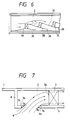
- a fourth embodiment of the invention a tunnel dust collecting system of upward suction type, is a shown in Fig. 7.
- contaminated air is led into a dust collecting chamber 2 through an air sucking inlet 9 as indicated by the arrows.
- the air sucking inlet 9 has an upstream wall 9a and a downstream wall 9b which are curved in section inwardly. More specifically, the upper and lower edges of the upstream wall 9a are continuously rounded with radii R1 and R2 (R1 > R2), respectively; and similarly, the upper and lower edges of the downstream wall 9b are continuously rounded with radii R2 and R1, respectively.
- the contaminated air is sucked through the air sucking inlet 9 into the dust collecting chamber 2 obliquely upwardly along the gradients of the upstream and downstream walls 9a and 9b. Therefore, the air thus sucked is allowed to go along the ceiling board, thus forming no contraction flow.
- the air flows to substantially the whole of the air sucking surface of the dust collector 3, so that it is decontaminated with high efficiency contacting the electrode boards not shown. In addition, the pressure loss at the air sucking inlet 9 is minimized.
- the tunnel dust collecting system of the invention has the following effects or merits:
- the nozzle is connected to the air outlet of each of the air blowers in such a manner that the decontaminated air is blown downwardly outwardly with respect to the central axis of the tunnel.
- the distance is reduced which is required for the decontaminated air supplied from the dust collector to mix the contaminated air in the tunnel, and accordingly the number of dust collecting systems per unitary length of a tunnel can be increased as much.
- the tunnel dust collecting system of the invention even a tunnel high in air contamination can be sufficiently ventilated.
- the power consumption of the air blowers in the system of the invention is smaller by 1 to 5 % than in the conventional system.
- a ventilated scaffold can be installed below the casings for maintenance of the air blowers.
- a plurality of dust collectors are provided in the dust collecting chamber in such a manner that they are arranged longitudinally of the dust collecting chamber and shifted from one another laterally of the dust collecting chamber (from one side wall of the dust collecting chamber towards the other side wall) as if they were overlapped when viewed from one end of the dust collecting chamber.
- the effective air flow area is increased, so that the flow rate of air to be processed per dust collecting system can be increased without increasing its dust collector installation space.
- the top dust collector is selected to be smaller than the remaining dust collectors, and the distance between the top and second dust collectors is made longer than those between the second and third dust collectors, between the third and fourth dust collector, and so forth, whereby the contaminated air led into the dust collecting chamber can be distributed uniformly to the dust collectors.
- the degrees of opening of the outlet dampers at each of the dust collectors are adjusted to finely control the flow rate of air therein.
- the air sucking inlet formed in the ceiling board has the first wall upstream thereof the upper and lower edges of which are rounded continuously with the first radius and the second radius smaller than the first radius, respectively, and the second wall downstream thereof the upper and lower edges of which are rounded continuously with the second and first radii, respectively.
Applications Claiming Priority (13)
| Application Number | Priority Date | Filing Date | Title |
|---|---|---|---|
| JP193523/89 | 1989-07-26 | ||
| JP19352389 | 1989-07-26 | ||
| JP19352389 | 1989-07-26 | ||
| JP21776089 | 1989-08-24 | ||
| JP21775189 | 1989-08-24 | ||
| JP217751/89 | 1989-08-24 | ||
| JP217760/89 | 1989-08-24 | ||
| JP21776089 | 1989-08-24 | ||
| JP21775189 | 1989-08-24 | ||
| JP21775389 | 1989-08-24 | ||
| JP21775389 | 1989-08-24 | ||
| JP217753/89 | 1989-08-24 | ||
| EP90114281A EP0410428B1 (fr) | 1989-07-26 | 1990-07-25 | Système de collecteur pour la poussière dans des tunnels |
Related Parent Applications (2)
| Application Number | Title | Priority Date | Filing Date |
|---|---|---|---|
| EP90114281.0 Division | 1990-07-25 | ||
| EP90114281A Division EP0410428B1 (fr) | 1989-07-26 | 1990-07-25 | Système de collecteur pour la poussière dans des tunnels |
Publications (2)
| Publication Number | Publication Date |
|---|---|
| EP0675263A1 true EP0675263A1 (fr) | 1995-10-04 |
| EP0675263B1 EP0675263B1 (fr) | 1999-12-01 |
Family
ID=27475654
Family Applications (4)
| Application Number | Title | Priority Date | Filing Date |
|---|---|---|---|
| EP93112603A Expired - Lifetime EP0577153B1 (fr) | 1989-07-26 | 1990-07-25 | Entrèe d'air aerodynamique d'un système de ventilation d'un tunnel |
| EP95107725A Expired - Lifetime EP0675263B1 (fr) | 1989-07-26 | 1990-07-25 | Système de collecteur pour la poussière dans des tunnels |
| EP94106613A Expired - Lifetime EP0613994B1 (fr) | 1989-07-26 | 1990-07-25 | Système collecteur de la poussière dans des Tunnels |
| EP90114281A Expired - Lifetime EP0410428B1 (fr) | 1989-07-26 | 1990-07-25 | Système de collecteur pour la poussière dans des tunnels |
Family Applications Before (1)
| Application Number | Title | Priority Date | Filing Date |
|---|---|---|---|
| EP93112603A Expired - Lifetime EP0577153B1 (fr) | 1989-07-26 | 1990-07-25 | Entrèe d'air aerodynamique d'un système de ventilation d'un tunnel |
Family Applications After (2)
| Application Number | Title | Priority Date | Filing Date |
|---|---|---|---|
| EP94106613A Expired - Lifetime EP0613994B1 (fr) | 1989-07-26 | 1990-07-25 | Système collecteur de la poussière dans des Tunnels |
| EP90114281A Expired - Lifetime EP0410428B1 (fr) | 1989-07-26 | 1990-07-25 | Système de collecteur pour la poussière dans des tunnels |
Country Status (2)
| Country | Link |
|---|---|
| EP (4) | EP0577153B1 (fr) |
| DE (4) | DE69031600T2 (fr) |
Cited By (5)
| Publication number | Priority date | Publication date | Assignee | Title |
|---|---|---|---|---|
| US6224796B1 (en) | 1998-08-19 | 2001-05-01 | CENTRE DE RECHERCHE INDUSTRIELLE DU QUéBEC | Process for producing batches of rubber-based composition |
| DE10136097A1 (de) * | 2001-06-13 | 2003-01-09 | Thyssenkrupp Hiserv Gmbh | Absaugvorrichtung für einen Tunnel |
| CN104475252A (zh) * | 2014-12-04 | 2015-04-01 | 佛山市科蓝环保科技股份有限公司 | 一种隧道空气净化设备 |
| CN106761890A (zh) * | 2017-01-11 | 2017-05-31 | 中国矿业大学 | 一种隧道施工除尘除烟辅助通风装置 |
| CN110159336A (zh) * | 2019-05-22 | 2019-08-23 | 中煤科工集团重庆研究院有限公司 | 一种适用于除尘器的除杂装置 |
Families Citing this family (14)
| Publication number | Priority date | Publication date | Assignee | Title |
|---|---|---|---|---|
| GB9416975D0 (en) * | 1994-08-23 | 1994-10-12 | South Bank Univ Entpr Ltd | Air moving system |
| WO2001009484A2 (fr) * | 1999-08-02 | 2001-02-08 | Rosenbauer International Aktiengesellschaft | Installation et procede pour lutter contre des sinistres dans un tunnel |
| EP1081331B1 (fr) * | 1999-09-02 | 2004-08-11 | Rud. Otto Meyer GmbH & Co. KG | Procédé et système d'aspiration pour la ventilation, p.e. de fumée dans des tunnels |
| EP1329588A1 (fr) * | 2002-01-17 | 2003-07-23 | Alexander Fasnacht | Dispositif d'alimentation d'air respiratoire dans le passage d'un tunnel |
| DE102009054031A1 (de) * | 2009-11-20 | 2011-05-26 | Wu, Fu-Chi, Northridge | Luftbehandlungsgerät |
| CN102125787B (zh) * | 2010-01-19 | 2013-04-10 | 哈尔滨辰能工大环保科技股份有限公司 | 径流式长袋低压脉冲袋式除尘器 |
| CN101906986A (zh) * | 2010-07-09 | 2010-12-08 | 胜利油田胜利动力机械集团有限公司 | 煤矿乏风装置进、排气气流分配方法 |
| CN102080558B (zh) * | 2010-11-08 | 2013-01-02 | 上海市城市建设设计研究院 | 一种道路隧道无排风井净化排风的方法 |
| CN104071241B (zh) * | 2014-05-27 | 2016-06-29 | 浙江大学 | 一种公路隧道空气除尘车及其除尘方法 |
| CN104948216B (zh) * | 2015-06-04 | 2017-06-16 | 浙江海洋学院 | 一种隧道用排水排风两用格栅 |
| JP7276857B2 (ja) * | 2017-05-04 | 2023-05-18 | モーゼン リミテッド | 最適化されたトンネル換気デバイス |
| CN108979697B (zh) * | 2018-08-09 | 2019-10-25 | 湖南科技大学 | 隧道开式循环通风的送风竖井新风风量折减系数计算方法 |
| CN111520179B (zh) * | 2020-05-19 | 2021-11-16 | 安徽宝龙电器有限公司 | 一种矿用本质安全性烟雾控制装置 |
| CN116025406B (zh) * | 2023-02-21 | 2024-01-02 | 中南大学 | 一种隧道除尘系统及其除尘方法 |
Citations (3)
| Publication number | Priority date | Publication date | Assignee | Title |
|---|---|---|---|---|
| FR2253877A1 (en) * | 1973-12-05 | 1975-07-04 | Sofrair | Pressure fed air ventilation for road tunnel - directs air tangentially down side wall from roof inlets |
| DE2509279A1 (de) * | 1975-03-04 | 1976-09-16 | Voith Getriebe Kg | Belueftungseinrichtung fuer den innenraum einer kuenstlichen strassenueberdeckung |
| JPS63319072A (ja) * | 1987-06-23 | 1988-12-27 | Fuji Electric Co Ltd | 道路用トンネルの集じん設備 |
Family Cites Families (5)
| Publication number | Priority date | Publication date | Assignee | Title |
|---|---|---|---|---|
| FR1226629A (fr) * | 1959-02-25 | 1960-07-13 | Neu Sa | Procédé et dispositif pour la ventilation d'un tunnel ferroviaire et routier |
| DE1459883C3 (de) * | 1963-03-26 | 1974-05-02 | J.M. Voith Gmbh, 7920 Heidenheim | Einrichtung zur Längsbelüftung eines Tunnels |
| CH433424A (de) * | 1964-06-09 | 1967-04-15 | Shb Installations Projekt Ag | Lüftungseinrichtung in Strassentunnel |
| AT308807B (de) * | 1968-01-15 | 1973-06-15 | Sina In Nat Autostradali | Anlage zur laengsbelueftung eines einbahnigen tunnels |
| DE3608308C1 (de) * | 1986-03-13 | 1987-01-08 | Turbo Lufttechnik Gmbh | Einrichtung zur Belueftung eines Tunnels |
-
1990
- 1990-07-25 DE DE1990631600 patent/DE69031600T2/de not_active Expired - Fee Related
- 1990-07-25 DE DE1990628818 patent/DE69028818T2/de not_active Expired - Fee Related
- 1990-07-25 EP EP93112603A patent/EP0577153B1/fr not_active Expired - Lifetime
- 1990-07-25 EP EP95107725A patent/EP0675263B1/fr not_active Expired - Lifetime
- 1990-07-25 EP EP94106613A patent/EP0613994B1/fr not_active Expired - Lifetime
- 1990-07-25 DE DE1990629277 patent/DE69029277T2/de not_active Expired - Fee Related
- 1990-07-25 DE DE1990633378 patent/DE69033378T2/de not_active Expired - Fee Related
- 1990-07-25 EP EP90114281A patent/EP0410428B1/fr not_active Expired - Lifetime
Patent Citations (3)
| Publication number | Priority date | Publication date | Assignee | Title |
|---|---|---|---|---|
| FR2253877A1 (en) * | 1973-12-05 | 1975-07-04 | Sofrair | Pressure fed air ventilation for road tunnel - directs air tangentially down side wall from roof inlets |
| DE2509279A1 (de) * | 1975-03-04 | 1976-09-16 | Voith Getriebe Kg | Belueftungseinrichtung fuer den innenraum einer kuenstlichen strassenueberdeckung |
| JPS63319072A (ja) * | 1987-06-23 | 1988-12-27 | Fuji Electric Co Ltd | 道路用トンネルの集じん設備 |
Non-Patent Citations (1)
| Title |
|---|
| PATENT ABSTRACTS OF JAPAN vol. 13, no. 169 (C - 587)<3517> 21 April 1989 (1989-04-21) * |
Cited By (6)
| Publication number | Priority date | Publication date | Assignee | Title |
|---|---|---|---|---|
| US6224796B1 (en) | 1998-08-19 | 2001-05-01 | CENTRE DE RECHERCHE INDUSTRIELLE DU QUéBEC | Process for producing batches of rubber-based composition |
| DE10136097A1 (de) * | 2001-06-13 | 2003-01-09 | Thyssenkrupp Hiserv Gmbh | Absaugvorrichtung für einen Tunnel |
| DE10136097C2 (de) * | 2001-06-13 | 2003-10-16 | Thyssenkrupp Hiserv Gmbh | Absaugvorrichtung für einen Tunnel |
| CN104475252A (zh) * | 2014-12-04 | 2015-04-01 | 佛山市科蓝环保科技股份有限公司 | 一种隧道空气净化设备 |
| CN106761890A (zh) * | 2017-01-11 | 2017-05-31 | 中国矿业大学 | 一种隧道施工除尘除烟辅助通风装置 |
| CN110159336A (zh) * | 2019-05-22 | 2019-08-23 | 中煤科工集团重庆研究院有限公司 | 一种适用于除尘器的除杂装置 |
Also Published As
| Publication number | Publication date |
|---|---|
| EP0410428A3 (en) | 1991-08-28 |
| EP0613994A1 (fr) | 1994-09-07 |
| DE69029277T2 (de) | 1997-03-27 |
| DE69028818T2 (de) | 1997-02-13 |
| EP0410428A2 (fr) | 1991-01-30 |
| DE69031600D1 (de) | 1997-11-20 |
| EP0675263B1 (fr) | 1999-12-01 |
| EP0577153A1 (fr) | 1994-01-05 |
| DE69031600T2 (de) | 1998-02-12 |
| EP0577153B1 (fr) | 1996-11-27 |
| DE69033378T2 (de) | 2000-04-06 |
| DE69028818D1 (de) | 1996-11-14 |
| DE69029277D1 (de) | 1997-01-09 |
| EP0613994B1 (fr) | 1997-10-15 |
| EP0410428B1 (fr) | 1996-10-09 |
| DE69033378D1 (de) | 2000-01-05 |
Similar Documents
| Publication | Publication Date | Title |
|---|---|---|
| EP0613994B1 (fr) | Système collecteur de la poussière dans des Tunnels | |
| US6451096B1 (en) | Air cleaner for removing air pollutants by water spray type of dust collecting system | |
| US7070637B1 (en) | Apparatus for separating particles from a fluid | |
| PT1604742E (pt) | Alimentação de gás para electrofiltro e dispositivo de electrofiltro | |
| US3332214A (en) | Method and apparatus for collecting contaminants from gases | |
| KR20230000031A (ko) | 집진 시스템 | |
| US4108615A (en) | Vaned anode for high-intensity ionizer stage of electrostatic precipitator | |
| US20010039877A1 (en) | Electrostatic precipitator | |
| US4695297A (en) | Electrostatic precipitator | |
| CA2148315C (fr) | Deflecteur d'admission de depoussiereur par voie humide, a faible perte de charge | |
| JPH03233099A (ja) | トンネル集じん装置 | |
| US4940471A (en) | Device for cleaning two-stage electrostatic precipitators | |
| DE112020006884T5 (de) | Lüftermodul und tragbarer Luftreiniger, der es enthält | |
| JP2953443B2 (ja) | トンネル集じん装置 | |
| CN219283544U (zh) | 一种隔断仓 | |
| RU2137531C1 (ru) | Устройство для очистки газов | |
| KR20000054562A (ko) | 수막 집진장치에 의한 유해물질 제거 공조장치 | |
| DE3712113C2 (de) | Selbstreinigendes Filter für gasförmige Medien und Verfahren zum Betreiben eines solchen Filters | |
| JP3637089B2 (ja) | 負イオン発生装置 | |
| RU2056906C1 (ru) | Инерционный пылеотделитель | |
| KR101897034B1 (ko) | 원료저장고 내부 집진환경 개선 시스템 | |
| JP3637097B2 (ja) | 負イオン発生装置 | |
| CN100382849C (zh) | 空气净化器的通道构造 | |
| JPH08261532A (ja) | クリーンルーム | |
| SU1161711A1 (ru) | Устройство дл вентил ции карьеров |
Legal Events
| Date | Code | Title | Description |
|---|---|---|---|
| PUAI | Public reference made under article 153(3) epc to a published international application that has entered the european phase |
Free format text: ORIGINAL CODE: 0009012 |
|
| 17P | Request for examination filed |
Effective date: 19950519 |
|
| AC | Divisional application: reference to earlier application |
Ref document number: 410428 Country of ref document: EP |
|
| AK | Designated contracting states |
Kind code of ref document: A1 Designated state(s): CH DE FR GB IT LI |
|
| 17Q | First examination report despatched |
Effective date: 19970917 |
|
| GRAG | Despatch of communication of intention to grant |
Free format text: ORIGINAL CODE: EPIDOS AGRA |
|
| GRAG | Despatch of communication of intention to grant |
Free format text: ORIGINAL CODE: EPIDOS AGRA |
|
| GRAH | Despatch of communication of intention to grant a patent |
Free format text: ORIGINAL CODE: EPIDOS IGRA |
|
| GRAH | Despatch of communication of intention to grant a patent |
Free format text: ORIGINAL CODE: EPIDOS IGRA |
|
| GRAA | (expected) grant |
Free format text: ORIGINAL CODE: 0009210 |
|
| AC | Divisional application: reference to earlier application |
Ref document number: 410428 Country of ref document: EP |
|
| AK | Designated contracting states |
Kind code of ref document: B1 Designated state(s): CH DE FR GB IT LI |
|
| REG | Reference to a national code |
Ref country code: CH Ref legal event code: NV Representative=s name: BOVARD AG PATENTANWAELTE Ref country code: CH Ref legal event code: EP |
|
| REF | Corresponds to: |
Ref document number: 69033378 Country of ref document: DE Date of ref document: 20000105 |
|
| ITF | It: translation for a ep patent filed |
Owner name: SOCIETA' ITALIANA BREVETTI S.P.A. |
|
| ET | Fr: translation filed | ||
| PLBE | No opposition filed within time limit |
Free format text: ORIGINAL CODE: 0009261 |
|
| STAA | Information on the status of an ep patent application or granted ep patent |
Free format text: STATUS: NO OPPOSITION FILED WITHIN TIME LIMIT |
|
| 26N | No opposition filed | ||
| REG | Reference to a national code |
Ref country code: GB Ref legal event code: IF02 |
|
| PGFP | Annual fee paid to national office [announced via postgrant information from national office to epo] |
Ref country code: FR Payment date: 20020709 Year of fee payment: 13 |
|
| REG | Reference to a national code |
Ref country code: GB Ref legal event code: 746 Effective date: 20020620 |
|
| PGFP | Annual fee paid to national office [announced via postgrant information from national office to epo] |
Ref country code: GB Payment date: 20020724 Year of fee payment: 13 |
|
| PGFP | Annual fee paid to national office [announced via postgrant information from national office to epo] |
Ref country code: DE Payment date: 20020731 Year of fee payment: 13 |
|
| PGFP | Annual fee paid to national office [announced via postgrant information from national office to epo] |
Ref country code: CH Payment date: 20020802 Year of fee payment: 13 |
|
| REG | Reference to a national code |
Ref country code: FR Ref legal event code: D6 |
|
| REG | Reference to a national code |
Ref country code: FR Ref legal event code: ST |
|
| PG25 | Lapsed in a contracting state [announced via postgrant information from national office to epo] |
Ref country code: GB Free format text: LAPSE BECAUSE OF NON-PAYMENT OF DUE FEES Effective date: 20030725 |
|
| PG25 | Lapsed in a contracting state [announced via postgrant information from national office to epo] |
Ref country code: LI Free format text: LAPSE BECAUSE OF NON-PAYMENT OF DUE FEES Effective date: 20030731 Ref country code: CH Free format text: LAPSE BECAUSE OF NON-PAYMENT OF DUE FEES Effective date: 20030731 |
|
| PG25 | Lapsed in a contracting state [announced via postgrant information from national office to epo] |
Ref country code: DE Free format text: LAPSE BECAUSE OF NON-PAYMENT OF DUE FEES Effective date: 20040203 |
|
| REG | Reference to a national code |
Ref country code: CH Ref legal event code: PL |
|
| GBPC | Gb: european patent ceased through non-payment of renewal fee |
Effective date: 20030725 |
|
| PG25 | Lapsed in a contracting state [announced via postgrant information from national office to epo] |
Ref country code: IT Free format text: LAPSE BECAUSE OF NON-PAYMENT OF DUE FEES;WARNING: LAPSES OF ITALIAN PATENTS WITH EFFECTIVE DATE BEFORE 2007 MAY HAVE OCCURRED AT ANY TIME BEFORE 2007. THE CORRECT EFFECTIVE DATE MAY BE DIFFERENT FROM THE ONE RECORDED. Effective date: 20050725 |
|
| PG25 | Lapsed in a contracting state [announced via postgrant information from national office to epo] |
Ref country code: FR Free format text: LAPSE BECAUSE OF NON-PAYMENT OF DUE FEES Effective date: 20030731 |