EP0675242A1 - Profilé porteur métallique pour panneaux tels que verrières - Google Patents
Profilé porteur métallique pour panneaux tels que verrières Download PDFInfo
- Publication number
- EP0675242A1 EP0675242A1 EP95400712A EP95400712A EP0675242A1 EP 0675242 A1 EP0675242 A1 EP 0675242A1 EP 95400712 A EP95400712 A EP 95400712A EP 95400712 A EP95400712 A EP 95400712A EP 0675242 A1 EP0675242 A1 EP 0675242A1
- Authority
- EP
- European Patent Office
- Prior art keywords
- profile
- grooves
- profile according
- bearing surface
- groove
- Prior art date
- Legal status (The legal status is an assumption and is not a legal conclusion. Google has not performed a legal analysis and makes no representation as to the accuracy of the status listed.)
- Granted
Links
- 239000002184 metal Substances 0.000 claims abstract description 14
- XLYOFNOQVPJJNP-UHFFFAOYSA-N water Substances O XLYOFNOQVPJJNP-UHFFFAOYSA-N 0.000 claims abstract description 10
- 238000005452 bending Methods 0.000 claims description 3
- 239000011521 glass Substances 0.000 abstract description 4
- 238000003466 welding Methods 0.000 abstract description 2
- 238000009434 installation Methods 0.000 description 3
- 238000004519 manufacturing process Methods 0.000 description 3
- 239000000463 material Substances 0.000 description 2
- 230000008094 contradictory effect Effects 0.000 description 1
- 238000007599 discharging Methods 0.000 description 1
- 238000000034 method Methods 0.000 description 1
Images
Classifications
-
- E—FIXED CONSTRUCTIONS
- E04—BUILDING
- E04C—STRUCTURAL ELEMENTS; BUILDING MATERIALS
- E04C3/00—Structural elongated elements designed for load-supporting
- E04C3/02—Joists; Girders, trusses, or trusslike structures, e.g. prefabricated; Lintels; Transoms; Braces
- E04C3/04—Joists; Girders, trusses, or trusslike structures, e.g. prefabricated; Lintels; Transoms; Braces of metal
- E04C3/06—Joists; Girders, trusses, or trusslike structures, e.g. prefabricated; Lintels; Transoms; Braces of metal with substantially solid, i.e. unapertured, web
- E04C3/065—Joists; Girders, trusses, or trusslike structures, e.g. prefabricated; Lintels; Transoms; Braces of metal with substantially solid, i.e. unapertured, web with special adaptations for the passage of cables or conduits through the web
-
- E—FIXED CONSTRUCTIONS
- E04—BUILDING
- E04C—STRUCTURAL ELEMENTS; BUILDING MATERIALS
- E04C3/00—Structural elongated elements designed for load-supporting
- E04C3/02—Joists; Girders, trusses, or trusslike structures, e.g. prefabricated; Lintels; Transoms; Braces
- E04C3/04—Joists; Girders, trusses, or trusslike structures, e.g. prefabricated; Lintels; Transoms; Braces of metal
- E04C3/06—Joists; Girders, trusses, or trusslike structures, e.g. prefabricated; Lintels; Transoms; Braces of metal with substantially solid, i.e. unapertured, web
- E04C3/07—Joists; Girders, trusses, or trusslike structures, e.g. prefabricated; Lintels; Transoms; Braces of metal with substantially solid, i.e. unapertured, web at least partly of bent or otherwise deformed strip- or sheet-like material
-
- E—FIXED CONSTRUCTIONS
- E04—BUILDING
- E04C—STRUCTURAL ELEMENTS; BUILDING MATERIALS
- E04C3/00—Structural elongated elements designed for load-supporting
- E04C3/02—Joists; Girders, trusses, or trusslike structures, e.g. prefabricated; Lintels; Transoms; Braces
- E04C3/29—Joists; Girders, trusses, or trusslike structures, e.g. prefabricated; Lintels; Transoms; Braces built-up from parts of different material, i.e. composite structures
- E04C3/292—Joists; Girders, trusses, or trusslike structures, e.g. prefabricated; Lintels; Transoms; Braces built-up from parts of different material, i.e. composite structures the materials being wood and metal
-
- E—FIXED CONSTRUCTIONS
- E04—BUILDING
- E04D—ROOF COVERINGS; SKY-LIGHTS; GUTTERS; ROOF-WORKING TOOLS
- E04D3/00—Roof covering by making use of flat or curved slabs or stiff sheets
- E04D3/02—Roof covering by making use of flat or curved slabs or stiff sheets of plane slabs, slates, or sheets, or in which the cross-section is unimportant
- E04D3/06—Roof covering by making use of flat or curved slabs or stiff sheets of plane slabs, slates, or sheets, or in which the cross-section is unimportant of glass or other translucent material; Fixing means therefor
- E04D3/08—Roof covering by making use of flat or curved slabs or stiff sheets of plane slabs, slates, or sheets, or in which the cross-section is unimportant of glass or other translucent material; Fixing means therefor with metal glazing bars
-
- E—FIXED CONSTRUCTIONS
- E04—BUILDING
- E04D—ROOF COVERINGS; SKY-LIGHTS; GUTTERS; ROOF-WORKING TOOLS
- E04D3/00—Roof covering by making use of flat or curved slabs or stiff sheets
- E04D3/02—Roof covering by making use of flat or curved slabs or stiff sheets of plane slabs, slates, or sheets, or in which the cross-section is unimportant
- E04D3/06—Roof covering by making use of flat or curved slabs or stiff sheets of plane slabs, slates, or sheets, or in which the cross-section is unimportant of glass or other translucent material; Fixing means therefor
- E04D3/14—Roof covering by making use of flat or curved slabs or stiff sheets of plane slabs, slates, or sheets, or in which the cross-section is unimportant of glass or other translucent material; Fixing means therefor with glazing bars of other material, e.g. of glass
-
- E—FIXED CONSTRUCTIONS
- E04—BUILDING
- E04B—GENERAL BUILDING CONSTRUCTIONS; WALLS, e.g. PARTITIONS; ROOFS; FLOORS; CEILINGS; INSULATION OR OTHER PROTECTION OF BUILDINGS
- E04B2/00—Walls, e.g. partitions, for buildings; Wall construction with regard to insulation; Connections specially adapted to walls
- E04B2/74—Removable non-load-bearing partitions; Partitions with a free upper edge
- E04B2/7407—Removable non-load-bearing partitions; Partitions with a free upper edge assembled using frames with infill panels or coverings only; made-up of panels and a support structure incorporating posts
- E04B2/7409—Removable non-load-bearing partitions; Partitions with a free upper edge assembled using frames with infill panels or coverings only; made-up of panels and a support structure incorporating posts special measures for sound or thermal insulation, including fire protection
- E04B2/7412—Posts or frame members specially adapted for reduced sound or heat transmission
-
- E—FIXED CONSTRUCTIONS
- E04—BUILDING
- E04C—STRUCTURAL ELEMENTS; BUILDING MATERIALS
- E04C3/00—Structural elongated elements designed for load-supporting
- E04C3/02—Joists; Girders, trusses, or trusslike structures, e.g. prefabricated; Lintels; Transoms; Braces
- E04C3/04—Joists; Girders, trusses, or trusslike structures, e.g. prefabricated; Lintels; Transoms; Braces of metal
- E04C2003/0404—Joists; Girders, trusses, or trusslike structures, e.g. prefabricated; Lintels; Transoms; Braces of metal beams, girders, or joists characterised by cross-sectional aspects
- E04C2003/0408—Joists; Girders, trusses, or trusslike structures, e.g. prefabricated; Lintels; Transoms; Braces of metal beams, girders, or joists characterised by cross-sectional aspects characterised by assembly or the cross-section
- E04C2003/0413—Joists; Girders, trusses, or trusslike structures, e.g. prefabricated; Lintels; Transoms; Braces of metal beams, girders, or joists characterised by cross-sectional aspects characterised by assembly or the cross-section being built up from several parts
-
- E—FIXED CONSTRUCTIONS
- E04—BUILDING
- E04C—STRUCTURAL ELEMENTS; BUILDING MATERIALS
- E04C3/00—Structural elongated elements designed for load-supporting
- E04C3/02—Joists; Girders, trusses, or trusslike structures, e.g. prefabricated; Lintels; Transoms; Braces
- E04C3/04—Joists; Girders, trusses, or trusslike structures, e.g. prefabricated; Lintels; Transoms; Braces of metal
- E04C2003/0404—Joists; Girders, trusses, or trusslike structures, e.g. prefabricated; Lintels; Transoms; Braces of metal beams, girders, or joists characterised by cross-sectional aspects
- E04C2003/0408—Joists; Girders, trusses, or trusslike structures, e.g. prefabricated; Lintels; Transoms; Braces of metal beams, girders, or joists characterised by cross-sectional aspects characterised by assembly or the cross-section
- E04C2003/0421—Joists; Girders, trusses, or trusslike structures, e.g. prefabricated; Lintels; Transoms; Braces of metal beams, girders, or joists characterised by cross-sectional aspects characterised by assembly or the cross-section comprising one single unitary part
-
- E—FIXED CONSTRUCTIONS
- E04—BUILDING
- E04C—STRUCTURAL ELEMENTS; BUILDING MATERIALS
- E04C3/00—Structural elongated elements designed for load-supporting
- E04C3/02—Joists; Girders, trusses, or trusslike structures, e.g. prefabricated; Lintels; Transoms; Braces
- E04C3/04—Joists; Girders, trusses, or trusslike structures, e.g. prefabricated; Lintels; Transoms; Braces of metal
- E04C2003/0404—Joists; Girders, trusses, or trusslike structures, e.g. prefabricated; Lintels; Transoms; Braces of metal beams, girders, or joists characterised by cross-sectional aspects
- E04C2003/0426—Joists; Girders, trusses, or trusslike structures, e.g. prefabricated; Lintels; Transoms; Braces of metal beams, girders, or joists characterised by cross-sectional aspects characterised by material distribution in cross section
- E04C2003/043—Joists; Girders, trusses, or trusslike structures, e.g. prefabricated; Lintels; Transoms; Braces of metal beams, girders, or joists characterised by cross-sectional aspects characterised by material distribution in cross section the hollow cross-section comprising at least one enclosed cavity
-
- E—FIXED CONSTRUCTIONS
- E04—BUILDING
- E04C—STRUCTURAL ELEMENTS; BUILDING MATERIALS
- E04C3/00—Structural elongated elements designed for load-supporting
- E04C3/02—Joists; Girders, trusses, or trusslike structures, e.g. prefabricated; Lintels; Transoms; Braces
- E04C3/04—Joists; Girders, trusses, or trusslike structures, e.g. prefabricated; Lintels; Transoms; Braces of metal
- E04C2003/0404—Joists; Girders, trusses, or trusslike structures, e.g. prefabricated; Lintels; Transoms; Braces of metal beams, girders, or joists characterised by cross-sectional aspects
- E04C2003/0426—Joists; Girders, trusses, or trusslike structures, e.g. prefabricated; Lintels; Transoms; Braces of metal beams, girders, or joists characterised by cross-sectional aspects characterised by material distribution in cross section
- E04C2003/0434—Joists; Girders, trusses, or trusslike structures, e.g. prefabricated; Lintels; Transoms; Braces of metal beams, girders, or joists characterised by cross-sectional aspects characterised by material distribution in cross section the open cross-section free of enclosed cavities
-
- E—FIXED CONSTRUCTIONS
- E04—BUILDING
- E04C—STRUCTURAL ELEMENTS; BUILDING MATERIALS
- E04C3/00—Structural elongated elements designed for load-supporting
- E04C3/02—Joists; Girders, trusses, or trusslike structures, e.g. prefabricated; Lintels; Transoms; Braces
- E04C3/04—Joists; Girders, trusses, or trusslike structures, e.g. prefabricated; Lintels; Transoms; Braces of metal
- E04C2003/0404—Joists; Girders, trusses, or trusslike structures, e.g. prefabricated; Lintels; Transoms; Braces of metal beams, girders, or joists characterised by cross-sectional aspects
- E04C2003/0443—Joists; Girders, trusses, or trusslike structures, e.g. prefabricated; Lintels; Transoms; Braces of metal beams, girders, or joists characterised by cross-sectional aspects characterised by substantial shape of the cross-section
- E04C2003/0473—U- or C-shaped
-
- E—FIXED CONSTRUCTIONS
- E04—BUILDING
- E04D—ROOF COVERINGS; SKY-LIGHTS; GUTTERS; ROOF-WORKING TOOLS
- E04D3/00—Roof covering by making use of flat or curved slabs or stiff sheets
- E04D3/02—Roof covering by making use of flat or curved slabs or stiff sheets of plane slabs, slates, or sheets, or in which the cross-section is unimportant
- E04D3/06—Roof covering by making use of flat or curved slabs or stiff sheets of plane slabs, slates, or sheets, or in which the cross-section is unimportant of glass or other translucent material; Fixing means therefor
- E04D3/08—Roof covering by making use of flat or curved slabs or stiff sheets of plane slabs, slates, or sheets, or in which the cross-section is unimportant of glass or other translucent material; Fixing means therefor with metal glazing bars
- E04D2003/0812—Roof covering by making use of flat or curved slabs or stiff sheets of plane slabs, slates, or sheets, or in which the cross-section is unimportant of glass or other translucent material; Fixing means therefor with metal glazing bars the supporting section of the glazing bar consisting of one single bent or otherwise deformed sheetmetal
-
- E—FIXED CONSTRUCTIONS
- E04—BUILDING
- E04D—ROOF COVERINGS; SKY-LIGHTS; GUTTERS; ROOF-WORKING TOOLS
- E04D3/00—Roof covering by making use of flat or curved slabs or stiff sheets
- E04D3/02—Roof covering by making use of flat or curved slabs or stiff sheets of plane slabs, slates, or sheets, or in which the cross-section is unimportant
- E04D3/06—Roof covering by making use of flat or curved slabs or stiff sheets of plane slabs, slates, or sheets, or in which the cross-section is unimportant of glass or other translucent material; Fixing means therefor
- E04D3/08—Roof covering by making use of flat or curved slabs or stiff sheets of plane slabs, slates, or sheets, or in which the cross-section is unimportant of glass or other translucent material; Fixing means therefor with metal glazing bars
- E04D2003/0818—Roof covering by making use of flat or curved slabs or stiff sheets of plane slabs, slates, or sheets, or in which the cross-section is unimportant of glass or other translucent material; Fixing means therefor with metal glazing bars the supporting section of the glazing bar consisting of several parts, e.g. compound sections
- E04D2003/0825—Roof covering by making use of flat or curved slabs or stiff sheets of plane slabs, slates, or sheets, or in which the cross-section is unimportant of glass or other translucent material; Fixing means therefor with metal glazing bars the supporting section of the glazing bar consisting of several parts, e.g. compound sections the metal section covered by parts of other material
-
- E—FIXED CONSTRUCTIONS
- E04—BUILDING
- E04D—ROOF COVERINGS; SKY-LIGHTS; GUTTERS; ROOF-WORKING TOOLS
- E04D3/00—Roof covering by making use of flat or curved slabs or stiff sheets
- E04D3/02—Roof covering by making use of flat or curved slabs or stiff sheets of plane slabs, slates, or sheets, or in which the cross-section is unimportant
- E04D3/06—Roof covering by making use of flat or curved slabs or stiff sheets of plane slabs, slates, or sheets, or in which the cross-section is unimportant of glass or other translucent material; Fixing means therefor
- E04D3/08—Roof covering by making use of flat or curved slabs or stiff sheets of plane slabs, slates, or sheets, or in which the cross-section is unimportant of glass or other translucent material; Fixing means therefor with metal glazing bars
- E04D2003/0818—Roof covering by making use of flat or curved slabs or stiff sheets of plane slabs, slates, or sheets, or in which the cross-section is unimportant of glass or other translucent material; Fixing means therefor with metal glazing bars the supporting section of the glazing bar consisting of several parts, e.g. compound sections
- E04D2003/0837—Sections comprising intermediate parts of insulating material
-
- E—FIXED CONSTRUCTIONS
- E04—BUILDING
- E04D—ROOF COVERINGS; SKY-LIGHTS; GUTTERS; ROOF-WORKING TOOLS
- E04D3/00—Roof covering by making use of flat or curved slabs or stiff sheets
- E04D3/02—Roof covering by making use of flat or curved slabs or stiff sheets of plane slabs, slates, or sheets, or in which the cross-section is unimportant
- E04D3/06—Roof covering by making use of flat or curved slabs or stiff sheets of plane slabs, slates, or sheets, or in which the cross-section is unimportant of glass or other translucent material; Fixing means therefor
- E04D3/08—Roof covering by making use of flat or curved slabs or stiff sheets of plane slabs, slates, or sheets, or in which the cross-section is unimportant of glass or other translucent material; Fixing means therefor with metal glazing bars
- E04D2003/0843—Clamping of the sheets or glass panes to the glazing bars by means of covering strips
- E04D2003/0856—Clamping of the sheets or glass panes to the glazing bars by means of covering strips locked by screws, bolts or pins
-
- E—FIXED CONSTRUCTIONS
- E04—BUILDING
- E04D—ROOF COVERINGS; SKY-LIGHTS; GUTTERS; ROOF-WORKING TOOLS
- E04D3/00—Roof covering by making use of flat or curved slabs or stiff sheets
- E04D3/02—Roof covering by making use of flat or curved slabs or stiff sheets of plane slabs, slates, or sheets, or in which the cross-section is unimportant
- E04D3/06—Roof covering by making use of flat or curved slabs or stiff sheets of plane slabs, slates, or sheets, or in which the cross-section is unimportant of glass or other translucent material; Fixing means therefor
- E04D3/08—Roof covering by making use of flat or curved slabs or stiff sheets of plane slabs, slates, or sheets, or in which the cross-section is unimportant of glass or other translucent material; Fixing means therefor with metal glazing bars
- E04D2003/0893—Glazing bars comprising means for draining condensation water or infiltrated rainwater
Definitions
- the present invention relates to an elongated metal profile, intended to constitute a supporting structure for panels, such as windows.
- the profiles of the invention are produced from extruded metal, or from sheet metal folded and / or welded, to produce elongated profiles of the type in particular comprising at least one bearing surface capable of receiving directly or indirectly a or more glass or other panels.
- Profiles of this type are already known, of generally quadrangular shape, comprising two respectively upper and lower flanks, each capable of forming a bearing surface for at least one panel, two parallel lateral flanks and at least two longitudinal grooves provided on the lateral sides, in the respective proximity of each bearing surface.
- Each bearing surface is separated into two parts by a recess capable of receiving means for securing the panels to the profile.
- the possibility of collecting and discharging runoff water requires a relatively complex embodiment, in particular at the junction of two perpendicular profiles.
- the respective shapes of the profiles, in particular grooves forming a gutter provided on the profiles, must be adapted to allow the flow of water from a profile in the perpendicular profile.
- the object of the present invention is to provide a metal profile of the type mentioned above, and allowing a flow of runoff water from one profile into another perpendicular profile, under easy conditions of installation and at reduced manufacturing cost.
- the elongated metal profile of generally quadrangular shape, of the type comprising two upper and lower sides respectively, capable of each forming a bearing surface for at least one panel (such as a window) , two parallel lateral flanks, and at least two longitudinal grooves provided on the lateral flanks in respective proximity of each bearing surface, each groove being shaped so as to produce a water drainage gutter, is characterized in that the distance between the bottom of one of the grooves and the nearest bearing surface, is greater than the corresponding distance and separating the bottom of the other groove from the other bearing surface.
- the profile of the invention has an asymmetry with respect to a longitudinal plane parallel to the bearing surfaces.
- a first profile being installed, a second profile perpendicular to it will be arranged so that the corresponding groove forming a gutter has a bottom located above the bottom of the groove of the first profile, so that water can flow from the second profile in the first.
- a single profile by simple turning, can be used to make an arrangement of two perpendicular profiles.
- the bearing surface is separated into two parts by a recess capable of receiving means for securing the panels to the profile.
- the profile has an axis of symmetry along a longitudinal plane transverse to the bearing surfaces, and more precisely the profile has two grooves arranged near a first bearing surface and two grooves arranged near the other surface. support, each set of two grooves being arranged on the respective lateral planes.
- the profile can be produced in one piece by deformation and bending of a metal tube, or by bending and plastic deformation of two metal strips and assembled edge to edge, by welding for example, to form the profile.
- FIG. 1 there is shown in section an arrangement of a first profile 1 and a second profile 2 perpendicular, and on which are placed and fixed panels, such as windows or the like bearing the references 3 and 4.
- the first profile 1 is shown in cross section and consists of a tubular element, of generally quadrangular shape, and preferably of rectangular section. Profiles 1 and 2 are produced from bent and plastically deformed metal tubes, or from bent or elastically deformed metal sheets or strips and welded edge to edge, or by any other method known per se.
- direction X For convenience, reference has been made to direction X as being horizontal and to direction Y as vertical.
- this comprises two lateral flanks 5 and 6, of vertical direction, and two respectively upper 7 and lower 8 flanks, both horizontal and planar.
- the upper sides 7 and 8 are separated into two parts 7A and 7B respectively by a recess in the form of a longitudinal groove, of reference 9 for the upper part and 10 for the lower part.
- the panels 3 and 4 are shown in support.
- the recess or central groove 9 is able to cooperate with means for securing the panels to the profile formed in the representation of FIG. 1, by a screw 11, a counter plate 12 bearing on the face of the panels opposite the profile, and a nut 13 cooperating with the screw 11, the nut being housed in the recess or central groove 9.
- On the lower part of the profile 8 is provided a cover plate or panel and bearing the reference 14, of any material known per se.
- Joints of suitable material 15 and 16 are provided between the bearing surfaces 7A, 7B on the one hand, and the panels 3 and 4, as well as between the counterplate 12 and the panels 3 and 4 on the other hand .
- the profile has longitudinal grooves forming a gutter, four in number and bearing the references 16 to 19. These grooves are intended to form gutters capable of receiving the flow water from possible leaks at the joints 15, in particular between panels and profile.
- the grooves / gutters 16 to 19 are in the general shape of a V with an oblique axis with respect to the bearing surfaces 7 and 8.
- the profile thus comprises two upper grooves 18 and 19 provided respectively on and near the lateral flanks 5 and 6 bearing surfaces 7B and 7A respectively.
- the grooves 16 and 17 are provided on each of the respective flanks 5 and 6, near the respective bearing surfaces 8A and 8B.
- the grooves / gutters are such that the V that they form comprises a branch whose end constitutes the end or the edge of the corresponding bearing surface.
- the other branch of the V has its end terminating at the level of the corresponding lateral flank.
- the junction between the end of the branches of the V and the support branches on the one hand and the lateral flanks on the other hand are rounded.
- the second profile 2, perpendicular to the first profile 1, is fixed and secured to the latter in a manner known per se and not shown.
- the second perpendicular profile 2 is arranged so that its respectively upper 20 and lower 21 bearing surfaces are at the same level as the bearing surfaces 7 and 8 respectively of the first profile 1. For reasons of clarity, the joints between the upper support surface 20 and panel 3 have not been shown.
- the respective arrangement of the perpendicular profiles 1 and 2 is such that the grooves / gutters of the second profile 2 (of which only the upper gutter 22 is shown) pour into the corresponding gutter 19 of the first profile 1.
- FIG. 2 shows a profile of the invention seen in section. We find in this figure the same references for elements similar or identical to those of Figure 1.
- the profile in the embodiment shown is made from two sheets or metal strips 23-24 folded and plastically deformed and welded edge to edge. edge by a weld line 25-26 at the bottom of the recess / groove 9 and 10 respectively.
- the profile of the invention is in particular shaped so as to have an asymmetry with respect to a transverse axis I-I, while it has symmetry with respect to a longitudinal axis II-II.
- the grooves / gutters are of different configurations for the grooves 18 and 19 near the upper bearing surfaces 7A and 7B, compared to the lower grooves 16 and 17 close to the lower bearing surfaces 8A and 8B.
- the grooves / gutters 16 and 19 arranged on the same lateral flank 5 are shaped so that the distance separating the bottom of the groove / gutter and the plane of the corresponding bearing surface is different for each gutter.
- the distance x between the bottom of the gutter 16 and the plane 8A is less than the distance X between the bottom of the gutter 19 and the bearing surface 7A.
- a single profile can be can be used to make an arrangement of perpendicular profiles, as shown in Figure 3, so that the gutters of one can pour into the corresponding gutters of the other.
- the second panel 2 has bearing surfaces 27A and 27B, arranged in the same plane X, Z as the bearing surfaces 7A and 7B of the profile 1.
- the second profile 2 has lateral flanks 28 and 29 and a groove / upper recess 30. For reasons of convenience, only the upper part of the sections 1 and 2 is shown.
- the first profile 1 is arranged so that the upper grooves / gutters 18 and 19 are the deepest, while the profile 2 is arranged so that its upper gutters 30 and 31 are the shallowest.
- the flow water from possible leaks at the joints between the glass panels supported by the structure formed by the profiles 1 and 2, flowing in the gutters 30 and 31 of the second panel 2 pours out ( arrow f) in the corresponding gutters 18 of the first section 1 arranged perpendicularly.
- the bottom of the shallowest gutters 30 and 31 of the second profile are arranged at a higher level (in the vertical direction Y, relative to the lower edges 18A, 19A, of the deepest gutters of the corresponding profile.
Abstract
Description
- La présente invention concerne un profilé métallique allongé, destiné à constituer une structure porteuse pour des panneaux, tels que des vitres.
- Plus particulièrement les profilés de l'invention sont réalisés à partir de métal extrudé, ou de métal en feuille pliée et/ou soudée, pour réaliser des profilés longiforme du type notamment comprenant au moins une surface d'appui apte à recevoir directement ou indirectement un ou plusieurs panneaux en verre ou autre.
- On connaît déjà des profilés de ce type, de forme générale quadrangulaire, comportant deux flancs respectivement supérieur et inférieur, aptes à former chacun une surface d'appui pour au moins un panneau, deux flancs latéraux parallèles et au moins deux rainures longitudinales prévues sur les flancs latéraux, à proximité respective de chaque surface d'appui. Chaque surface d'appui est séparée en deux parties par un évidement apte à recevoir des moyens de solidarisation des panneaux sur le profilé.
- Parmi les nombreuses contraintes et conditions que doivent satisfaire ces profilés, on retient plus particulièrement la commodité et facilité de mise en place, le coût faible de fabrication, la rigidité et fiabilité, et l'aptitude à recueillir et évacuer les eaux résultant des fuites éventuelles à la jonction entre les panneaux et les profilés.
- Les profilés connus sont en général aptes à répondre à la majorité, voire la quasi-totalité des contraintes.
- Cependant, ceci n'est obtenu qu'au prix d'un certain compromis, puisque ces contraintes et conditions sont contradictoires.
- Ainsi, par exemple, la possibilité de recueillir et évacuer les eaux de ruissellement suppose une forme de réalisation relativement complexe, notamment au niveau de la jonction de deux profilés perpendiculaires. Les formes respectives des profilés, notamment des rainures formant gouttière prévues sur les profilés, doivent être adaptées pour permettre l'écoulement des eaux d'un profilé dans le profilé perpendiculaire.
- Les profilés connus ne donnent pas entièrement satisfaction à cet égard et sont susceptibles de perfectionnement.
- L'objet de la présente invention est de proposer un profilé métallique du type mentionné ci-dessus, et permettant un écoulement de l'eau de ruissellement d'un profilé dans un autre profilé perpendiculaire, dans des conditions aisées de mise en place et à un coût de fabrication réduit.
- A cette fin, selon l'invention, le profilé métallique allongé, de forme générale quadrangulaire, du type comportant deux flancs respectivement supérieur et inférieur, aptes à former chacun une surface d'appui pour au moins un panneau (tel qu'une vitre), deux flancs latéraux parallèles, et au moins deux rainures longitudinales prévues sur les flancs latéraux à proximité respective de chaque surface d'appui, chaque rainure étant conformée de manière à réaliser une gouttière d'écoulement d'eau, est caractérisé en ce que la distance entre le fond d'une des rainures et la surface d'appui la plus proche, est plus grande que la distance correspondante et séparant le fond de l'autre rainure de l'autre surface d'appui.
- Il en résulte que le profilé de l'invention présente une dissymétrie par rapport à un plan longitudinal parallèle aux surfaces d'appui.
- Un premier profilé étant installé, un second profilé perpendiculaire à celui-ci sera disposé de manière que la rainure formant gouttière correspondante ait un fond situé au-dessus du fond de la rainure du premier profilé, afin que l'eau puisse d'écouler du second profilé dans le premier.
- Ainsi, un seul et même profilé, par simple retournement, peut être utilisé pour réaliser un agencement de deux profilés perpendiculaires.
- Il en résulte un coût réduit de fabrication et une simplification de mise en place et de conception appréciable.
- Selon une variante, la surface d'appui est séparée en deux parties par un évidement apte à recevoir des moyens de solidarisation des panneaux sur le profilé.
- Avantageusement, le profilé présente un axe de symétrie selon un plan longitudinal transversal aux surfaces d'appui, et plus précisément le profilé comporte deux rainures disposées à proximité d'une première surface d'appui et deux rainures disposées à proximité de l'autre surface d'appui, chaque jeu de deux rainures étant disposés sur les plans latéraux respectifs.
- Le profilé peut être réalisé en une seule pièce par déformation et pliage d'un tube métallique, ou par pliage et déformation plastique de deux bandes métalliques et assemblées bord à bord, par soudage par exemple, pour former le profilé.
- L'invention sera bien comprise à la lumière de la description qui suit, se rapportant à un exemple illustratif mais non limitatif de l'invention, en référence aux dessins annexés dans lesquels :
- la figure 1 est une vue en coupe transversale d'un profilé associé à deux panneaux et profilé perpendiculaire ;
- la figure 2 est une vue en coupe transversale du profilé de l'invention ; et
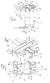
- la figure 3 est une vue en perspective partielle d'un agencement de deux profilés perpendiculaires conformes à l'invention.
- En référence à la figure 1, il est représenté en coupe un agencement d'un premier profilé 1 et d'un second profilé 2 perpendiculaires, et sur lesquels sont posés et fixés des panneaux, tels que des vitres ou analogues portant les références 3 et 4.
- Le premier profilé 1 est représenté en coupe transversale et est constitué d'un élément tubulaire, de forme générale quadrangulaire, et de préférence à section rectangulaire. Les profilés 1 et 2 sont réalisés à partir de tubes métalliques pliés et déformés plastiquement, ou de feuilles ou bandes métalliques pliées ou déformées élastiquement et soudées bord à bord, ou par toute autre méthode connue en soi.
- Par raison de commodité, on a référencé la direction X comme étant l'horizontale et la direction Y comme la verticale.
- En référence au profilé 1 représenté en coupe sur la figure 1, celui-ci comprend deux flancs latéraux 5 et 6, de direction verticale, et deux flancs respectivement supérieur 7 et inférieur 8, tous deux horizontaux et plans. Les flancs supérieurs 7 et 8 sont séparés en deux parties respectivement 7A et 7B par un évidement en forme de rainure longitudinale, de référence 9 pour la partie supérieure et 10 pour la partie inférieure. Sur les surfaces d'appui 7A et 7B sont représentés en appui les panneaux 3 et 4. L'évidement ou rainure centrale 9 est apte à coopérer avec des moyens de solidarisation des panneaux sur le profilé constitué dans la représentation de la figure 1, par une vis 11, une contre-plaque 12 portant sur la face des panneaux opposée au profilé, et un écrou 13 coopérant avec la vis 11, l'écrou étant logé dans l'évidement ou rainure centrale 9. Sur la partie inférieure du profilé 8, est prévue une plaque ou panneau de recouvrement et portant la référence 14, en tout matériau connu en soi.
- Des joints en matériau approprié 15 et 16 sont prévus entre les surfaces d'appui 7A, 7B d'une part, et les panneaux 3 et 4, ainsi qu'entre la contre-plaque 12 et les panneaux 3 et 4 d'autre part.
- Le profilé comporte des rainures longitudinales formant gouttière, au nombre de quatre et portant les références 16 à 19. Ces rainures sont destinées à former des gouttières aptes à recevoir l'eau d'écoulement provenant des fuites éventuelles au niveau des joints 15, notamment entre les panneaux et le profilé.
- Les rainures/gouttières 16 à 19 sont en forme générale de V d'axe oblique par rapport aux surfaces d'appui 7 et 8. Le profilé comporte ainsi deux rainures supérieures 18 et 19 prévues respectivement sur les flancs latéraux 5 et 6 et à proximité des surfaces d'appui respectivement 7B et 7A. Les rainures 16 et 17 sont prévues sur chacun des flancs respectifs 5 et 6, à proximité des surfaces d'appui respectives 8A et 8B.
- Plus précisément, les rainures/gouttières sont telles que le V qu'elles forment comporte une branche dont l'extrémité constitue l'extrémité ou le bord de la surface d'appui correspondante. L'autre branche du V a son extrémité aboutissant au niveau du flanc latéral correspondant. La jonction entre l'extrémité des branches du V et les branches d'appui d'une part et les flancs latéraux d'autre part sont arrondis.
- Le second profilé 2, perpendiculaire au premier profilé 1, est fixé et solidarisé à celui-ci de manière connue en soi et non représentée. Le second profilé 2 perpendiculaire est disposé de manière que ses surfaces d'appui respectivement supérieure 20 et inférieure 21 soient au même niveau que les surfaces d'appui respectivement 7 et 8 du premier profilé 1. Pour des raisons de clarté, les joints entre la surface d'appui supérieure 20 et le panneau 3 n'ont pas été représentés.
- La disposition respective des profilés perpendiculaires 1 et 2 est telle que les rainures/gouttières du second profilé 2 (dont seule la gouttière 22 supérieure est représentée) déversent dans la gouttière 19 correspondante du premier profilé 1.
- On a représenté sur la figure 2 un profilé de l'invention vu en coupe. On retrouve sur cette figure les mêmes références pour des éléments similaires ou identiques à ceux de la figure 1. Le profilé sous la forme de réalisation représentée est réalisé à partir de deux feuilles ou bandes métalliques 23-24 pliées et déformées plastiquement et soudées bord à bord par une ligne de soudure 25-26 au niveau du fond de l'évidement/rainure respectivement 9 et 10.
- Le profilé de l'invention est notamment conformé de manière à présenter une dissymétrie par rapport à un axe transversal I-I, alors qu'il présente une symétrie par rapport à un axe longitudinal II-II.
- Plus précisément, les rainures/gouttières sont de configurations différentes pour les rainures 18 et 19 à proximité des surfaces d'appui supérieures 7A et 7B, par rapport aux rainures 16 et 17 inférieures proches des surfaces d'appui inférieures 8A et 8B. Ainsi, pour les rainures/gouttières 16 et 19 disposées sur le même flanc latéral 5, sont conformées de manière que la distance séparant le fond de la rainure/gouttière et le plan de la surface d'appui correspondante est différente pour chaque gouttière. La distance x entre le fond de la gouttière 16 et le plan 8A est inférieure à la distance X entre le fond de la gouttière 19 et la surface d'appui 7A.
- On comprend que un seul et même profilé peut être peut être utilisé pour réaliser un agencement de profilés perpendiculaires, tel que montré sur la figure 3, de manière que les gouttières de l'un puissent se déverser dans les gouttières correspondantes de l'autre.
- On retrouve sur la figure 3 les mêmes références pour les éléments identiques ou similaires. On a défini une direction Z longitudinale perpendiculaire au plan formé par les directions orthogonales X transversale et Y verticale. Le premier profilé 1 est de direction Z, tandis que le second profilé perpendiculaire 2 est de direction X. Pour des raisons de clarté, les panneaux de verre ou similaire n'ont pas été représentés sur la figure 3, ainsi que les moyens de fixation de ces derniers sur le profilé, et les joints d'étanchéité.
- Le second panneau 2 comporte des surfaces d'appui 27A et 27B, disposées dans le même plan X, Z que les surfaces d'appui 7A et 7B du profilé 1. Le second profilé 2 comporte des flancs latéraux 28 et 29 et une rainure/évidement supérieure 30. Pour des raisons de commodité, seule la partie supérieure des profilés 1 et 2 est représentée.
- Le premier profilé 1 est disposé de manière que les rainures/gouttières supérieures 18 et 19 soient les plus profondes, tandis que le profilé 2 est disposé de manière que ses gouttières supérieures 30 et 31 soient les moins profondes. Ainsi, l'eau d'écoulement provenant de fuites éventuelles au niveau des joints entre les panneaux de verre supportés par la structure formée par les profilés 1 et 2, s'écoulant dans les gouttières 30 et 31 du second panneau 2, se déverse (flèche f) dans les gouttières correspondantes 18 du premier profilé 1 disposé perpendiculairement. En effet, le fond des gouttières les moins profondes 30 et 31 du second profilé, sont disposées à un niveau supérieur (dans la direction verticale Y, par rapport aux bords inférieurs 18A, 19A, des gouttières les plus profondes du profilé correspondant.
- A titre d'exemple indicatif, les dimensions du profilé peuvent être les suivantes, vue en coupe transversale :
- hauteur (direction Y) : 130 millimètres;
- largeur (direction X) : 60 millimètres;
- diamètre de l'évidement/rainure (9,10) : 21 millimètres;
- distance X de rainure peu provonde : 20 millimètres;
- distance X de rainure profonde : 25 millimètres.
Claims (9)
Applications Claiming Priority (2)
| Application Number | Priority Date | Filing Date | Title |
|---|---|---|---|
| FR9403743 | 1994-03-30 | ||
| FR9403743A FR2718174B1 (fr) | 1994-03-30 | 1994-03-30 | Profilé porteur à haute résistance thermique et agencement par exemple verrière comportant un tel profilé. |
Publications (2)
| Publication Number | Publication Date |
|---|---|
| EP0675242A1 true EP0675242A1 (fr) | 1995-10-04 |
| EP0675242B1 EP0675242B1 (fr) | 2001-11-28 |
Family
ID=9461581
Family Applications (2)
| Application Number | Title | Priority Date | Filing Date |
|---|---|---|---|
| EP95400712A Expired - Lifetime EP0675242B1 (fr) | 1994-03-30 | 1995-03-30 | Profilé porteur métallique pour panneaux tels que verrières |
| EP95400713A Withdrawn EP0676513A1 (fr) | 1994-03-30 | 1995-03-30 | Profilé porteur à haute résistance thermique et agencement par exemple verrière comportant un tel profilé |
Family Applications After (1)
| Application Number | Title | Priority Date | Filing Date |
|---|---|---|---|
| EP95400713A Withdrawn EP0676513A1 (fr) | 1994-03-30 | 1995-03-30 | Profilé porteur à haute résistance thermique et agencement par exemple verrière comportant un tel profilé |
Country Status (4)
| Country | Link |
|---|---|
| EP (2) | EP0675242B1 (fr) |
| AT (1) | ATE209743T1 (fr) |
| DE (1) | DE69524131D1 (fr) |
| FR (1) | FR2718174B1 (fr) |
Cited By (1)
| Publication number | Priority date | Publication date | Assignee | Title |
|---|---|---|---|---|
| FR2766905A1 (fr) * | 1997-07-11 | 1999-02-05 | Placoplatre Sa | Profile a rainure(s) pour la mise en place d'au moins un accessoire |
Families Citing this family (4)
| Publication number | Priority date | Publication date | Assignee | Title |
|---|---|---|---|---|
| AUPQ052199A0 (en) * | 1999-05-21 | 1999-06-17 | Wiltin Pty Ltd | Joining arrangements for structural members |
| US20060283130A1 (en) | 2005-06-07 | 2006-12-21 | William Andrews | Structural members with gripping features and joining arrangements therefor |
| US8061099B2 (en) | 2009-05-19 | 2011-11-22 | Tsf Systems, Llc | Vertical deflection extension end member |
| CZ35284U1 (cs) * | 2021-06-28 | 2021-07-27 | Alca Plast, S.R.O. | Konstrukční profil pro suchou výstavbu stěn, příček, podhledů a pro fixaci sanitárních zařízení |
Citations (8)
| Publication number | Priority date | Publication date | Assignee | Title |
|---|---|---|---|---|
| US1634288A (en) * | 1925-07-23 | 1927-07-05 | Hoefel Frederick | Skylight |
| US1963056A (en) * | 1930-10-03 | 1934-06-12 | American Fork & Hoe Co | Internally ribbed tube |
| GB582340A (en) * | 1944-04-21 | 1946-11-13 | Sankey & Sons Ltd Joseph | Improvements in sheet metal building sections |
| FR2316013A1 (fr) * | 1975-06-30 | 1977-01-28 | Palmer Shile Co | Procede de fabrication d'une poutre fermee et poutre en resultant |
| CA1208872A (fr) * | 1984-09-24 | 1986-08-05 | Francois X. Laroche | Joints de panneaux pour le batiment |
| DE3532507A1 (de) * | 1985-04-15 | 1987-03-19 | Moeller Automation Gmbh | Tragprofile fuer montageeinrichtungen, stuetzkonstruktionen und transportbaender |
| US4745723A (en) * | 1987-03-13 | 1988-05-24 | Four Seasons Solar Products Corporation | Glazing gasket and related supporting structure and method |
| US4974385A (en) * | 1989-05-11 | 1990-12-04 | Naturalite/Epi, Inc. | Purlin and rafter interconnection system |
Family Cites Families (11)
| Publication number | Priority date | Publication date | Assignee | Title |
|---|---|---|---|---|
| GB110123A (en) * | 1917-05-29 | 1917-10-11 | William Pitt Waugh | An Improved Glazing Construction. |
| FR1229772A (fr) * | 1959-02-17 | 1960-09-09 | Profilé standard de soutien | |
| GB1159956A (en) * | 1965-09-14 | 1969-07-30 | Donald Thomas Hill | Structural Building Unit |
| FR2151641A6 (fr) * | 1971-09-07 | 1973-04-20 | Goutheraud Et Cie | |
| EP0044270B1 (fr) * | 1980-06-30 | 1984-07-25 | Ciba-Geigy Ag | Composition intumescente retardatrice de flammes et ses applications à l'ignifugation de substrats et comme extincteur |
| DE3439436A1 (de) * | 1984-10-27 | 1986-04-30 | SCHÜCO Heinz Schürmann GmbH & Co, 4800 Bielefeld | Aussenwand- und dachverglasung |
| DE3634729A1 (de) * | 1986-10-31 | 1987-05-27 | Manfred Neu | Bauelement zum befestigen von glasscheiben |
| SE457364B (sv) * | 1987-05-11 | 1988-12-19 | Joergen Thor | Brandmotstaandskraftig bjaelklagsbalk av staal i samverkan med betong |
| DE3739741A1 (de) * | 1987-11-24 | 1989-06-08 | August Eich | Glasdach |
| US4850167A (en) * | 1988-02-08 | 1989-07-25 | Architectural Aluminum, Inc. | Structural glazing systems for skylights |
| WO1993015353A1 (fr) * | 1992-01-24 | 1993-08-05 | Rmt Pty. Ltd. | Profile destine a un element porteur composite |
-
1994
- 1994-03-30 FR FR9403743A patent/FR2718174B1/fr not_active Expired - Fee Related
-
1995
- 1995-03-30 EP EP95400712A patent/EP0675242B1/fr not_active Expired - Lifetime
- 1995-03-30 AT AT95400712T patent/ATE209743T1/de not_active IP Right Cessation
- 1995-03-30 EP EP95400713A patent/EP0676513A1/fr not_active Withdrawn
- 1995-03-30 DE DE69524131T patent/DE69524131D1/de not_active Expired - Lifetime
Patent Citations (8)
| Publication number | Priority date | Publication date | Assignee | Title |
|---|---|---|---|---|
| US1634288A (en) * | 1925-07-23 | 1927-07-05 | Hoefel Frederick | Skylight |
| US1963056A (en) * | 1930-10-03 | 1934-06-12 | American Fork & Hoe Co | Internally ribbed tube |
| GB582340A (en) * | 1944-04-21 | 1946-11-13 | Sankey & Sons Ltd Joseph | Improvements in sheet metal building sections |
| FR2316013A1 (fr) * | 1975-06-30 | 1977-01-28 | Palmer Shile Co | Procede de fabrication d'une poutre fermee et poutre en resultant |
| CA1208872A (fr) * | 1984-09-24 | 1986-08-05 | Francois X. Laroche | Joints de panneaux pour le batiment |
| DE3532507A1 (de) * | 1985-04-15 | 1987-03-19 | Moeller Automation Gmbh | Tragprofile fuer montageeinrichtungen, stuetzkonstruktionen und transportbaender |
| US4745723A (en) * | 1987-03-13 | 1988-05-24 | Four Seasons Solar Products Corporation | Glazing gasket and related supporting structure and method |
| US4974385A (en) * | 1989-05-11 | 1990-12-04 | Naturalite/Epi, Inc. | Purlin and rafter interconnection system |
Cited By (1)
| Publication number | Priority date | Publication date | Assignee | Title |
|---|---|---|---|---|
| FR2766905A1 (fr) * | 1997-07-11 | 1999-02-05 | Placoplatre Sa | Profile a rainure(s) pour la mise en place d'au moins un accessoire |
Also Published As
| Publication number | Publication date |
|---|---|
| ATE209743T1 (de) | 2001-12-15 |
| DE69524131D1 (de) | 2002-01-10 |
| EP0676513A1 (fr) | 1995-10-11 |
| EP0675242B1 (fr) | 2001-11-28 |
| FR2718174A1 (fr) | 1995-10-06 |
| FR2718174B1 (fr) | 1996-05-03 |
Similar Documents
| Publication | Publication Date | Title |
|---|---|---|
| EP3681746B1 (fr) | Profilé lécheur de vitre avec montage facilité | |
| EP2349871B1 (fr) | Dispositif et ensemble de maintien d'une paire de balais d'essuie-glaces, emballage et procede de montage correspondants | |
| EP0117816A2 (fr) | Montage par collage d'un vitrage dans une baie, avec maintien du vitrage à distance de la baie | |
| EP0675242B1 (fr) | Profilé porteur métallique pour panneaux tels que verrières | |
| FR2717843A1 (fr) | Faux plafond comportant une armature suspendue pourvue d'éléments décoratifs, et armature suspendue pour ce faux plafond. | |
| EP1580102B1 (fr) | Procédé d'assemblage d'un pavillon en aluminium sur les flancs d'une caisse d'un véhicule automobile et pavillon en aluminium pour véhicle automobile | |
| EP1978325B1 (fr) | Joue avec zone d`affaiblissement pour un echangeur de chaleur | |
| FR3036011B1 (fr) | Systeme de fixation d'un panneau sur un longeron et structure porteuse le comprenant | |
| EP2607564B1 (fr) | Lisse pour cadre de fausse paroi notamment de faux plafond | |
| FR2623228A1 (fr) | Couverture en panneaux profiles de matiere synthetique, notamment pour verandas, et procede pour assembler ces panneaux | |
| FR2957101A1 (fr) | Dispositif de type element de couverture et de toiture | |
| FR2766904A1 (fr) | Profile a section transversale du type en c susceptible d'etre associe a lui-meme par emboitement | |
| EP0983408B1 (fr) | Element de couverture | |
| EP1710386A1 (fr) | Système d'encastrement du bord d'un panneau ou analogue dans un montant | |
| EP0537093A1 (fr) | Structure-support pour essuie-glaces pour véhicules | |
| FR2762071A3 (fr) | Fixation perfectionnee d'une poutre et elements de fixation utilises a cet effet | |
| FR2616822A1 (fr) | Dispositif de fixation d'un panneau sur des montants | |
| EP0494029B1 (fr) | Panneau métallique pour habillage ou remplissage de structures porteuses, notamment de façades ou couvertures | |
| FR2766507A1 (fr) | Dispositif pour la fixation d'un capot decoratif exterieur, pour facade de mur rideau d'immeuble ou analogue | |
| FR2958615A1 (fr) | Traverse de baie d'un vehicule. | |
| EP1197609A1 (fr) | Armature de support pour panneaux vitrés d'une façade à mur rideau | |
| FR3121069A1 (fr) | Vitrage comportant plusieurs feuilles contigues et procede de fabrication de ce vitrage | |
| FR2750485A1 (fr) | Liaison tubes-collecteur a etancheite amelioree pour radiateur de vehicule | |
| BE564926A (fr) | ||
| FR2898369A1 (fr) | Cloison vitree formee de modules vitres a bords libres |
Legal Events
| Date | Code | Title | Description |
|---|---|---|---|
| PUAI | Public reference made under article 153(3) epc to a published international application that has entered the european phase |
Free format text: ORIGINAL CODE: 0009012 |
|
| AK | Designated contracting states |
Kind code of ref document: A1 Designated state(s): AT BE CH DE DK ES FR GB LI LU NL SE |
|
| 17P | Request for examination filed |
Effective date: 19951012 |
|
| 17Q | First examination report despatched |
Effective date: 19970908 |
|
| GRAG | Despatch of communication of intention to grant |
Free format text: ORIGINAL CODE: EPIDOS AGRA |
|
| GRAG | Despatch of communication of intention to grant |
Free format text: ORIGINAL CODE: EPIDOS AGRA |
|
| GRAH | Despatch of communication of intention to grant a patent |
Free format text: ORIGINAL CODE: EPIDOS IGRA |
|
| GRAH | Despatch of communication of intention to grant a patent |
Free format text: ORIGINAL CODE: EPIDOS IGRA |
|
| GRAA | (expected) grant |
Free format text: ORIGINAL CODE: 0009210 |
|
| AK | Designated contracting states |
Kind code of ref document: B1 Designated state(s): AT BE CH DE DK ES FR GB LI LU NL SE |
|
| PG25 | Lapsed in a contracting state [announced via postgrant information from national office to epo] |
Ref country code: NL Free format text: LAPSE BECAUSE OF FAILURE TO SUBMIT A TRANSLATION OF THE DESCRIPTION OR TO PAY THE FEE WITHIN THE PRESCRIBED TIME-LIMIT Effective date: 20011128 Ref country code: GB Free format text: LAPSE BECAUSE OF FAILURE TO SUBMIT A TRANSLATION OF THE DESCRIPTION OR TO PAY THE FEE WITHIN THE PRESCRIBED TIME-LIMIT Effective date: 20011128 Ref country code: AT Free format text: LAPSE BECAUSE OF FAILURE TO SUBMIT A TRANSLATION OF THE DESCRIPTION OR TO PAY THE FEE WITHIN THE PRESCRIBED TIME-LIMIT Effective date: 20011128 |
|
| REF | Corresponds to: |
Ref document number: 209743 Country of ref document: AT Date of ref document: 20011215 Kind code of ref document: T |
|
| REG | Reference to a national code |
Ref country code: CH Ref legal event code: EP |
|
| REG | Reference to a national code |
Ref country code: GB Ref legal event code: IF02 |
|
| REF | Corresponds to: |
Ref document number: 69524131 Country of ref document: DE Date of ref document: 20020110 |
|
| PG25 | Lapsed in a contracting state [announced via postgrant information from national office to epo] |
Ref country code: SE Free format text: LAPSE BECAUSE OF FAILURE TO SUBMIT A TRANSLATION OF THE DESCRIPTION OR TO PAY THE FEE WITHIN THE PRESCRIBED TIME-LIMIT Effective date: 20020228 Ref country code: DK Free format text: LAPSE BECAUSE OF FAILURE TO SUBMIT A TRANSLATION OF THE DESCRIPTION OR TO PAY THE FEE WITHIN THE PRESCRIBED TIME-LIMIT Effective date: 20020228 |
|
| PG25 | Lapsed in a contracting state [announced via postgrant information from national office to epo] |
Ref country code: DE Free format text: LAPSE BECAUSE OF FAILURE TO SUBMIT A TRANSLATION OF THE DESCRIPTION OR TO PAY THE FEE WITHIN THE PRESCRIBED TIME-LIMIT Effective date: 20020301 |
|
| REG | Reference to a national code |
Ref country code: CH Ref legal event code: NV Representative=s name: INFOSUISSE INFORMATION HORLOGERE ET INDUSTRIELLE |
|
| NLV1 | Nl: lapsed or annulled due to failure to fulfill the requirements of art. 29p and 29m of the patents act | ||
| GBV | Gb: ep patent (uk) treated as always having been void in accordance with gb section 77(7)/1977 [no translation filed] |
Effective date: 20011128 |
|
| PG25 | Lapsed in a contracting state [announced via postgrant information from national office to epo] |
Ref country code: ES Free format text: LAPSE BECAUSE OF FAILURE TO SUBMIT A TRANSLATION OF THE DESCRIPTION OR TO PAY THE FEE WITHIN THE PRESCRIBED TIME-LIMIT Effective date: 20020530 |
|
| PLBE | No opposition filed within time limit |
Free format text: ORIGINAL CODE: 0009261 |
|
| STAA | Information on the status of an ep patent application or granted ep patent |
Free format text: STATUS: NO OPPOSITION FILED WITHIN TIME LIMIT |
|
| 26N | No opposition filed | ||
| PGFP | Annual fee paid to national office [announced via postgrant information from national office to epo] |
Ref country code: LU Payment date: 20060331 Year of fee payment: 12 Ref country code: CH Payment date: 20060331 Year of fee payment: 12 |
|
| PGFP | Annual fee paid to national office [announced via postgrant information from national office to epo] |
Ref country code: BE Payment date: 20060403 Year of fee payment: 12 |
|
| REG | Reference to a national code |
Ref country code: CH Ref legal event code: PL |
|
| BERE | Be: lapsed |
Owner name: S.A. *LAUBEUF Effective date: 20070331 |
|
| PG25 | Lapsed in a contracting state [announced via postgrant information from national office to epo] |
Ref country code: BE Free format text: LAPSE BECAUSE OF NON-PAYMENT OF DUE FEES Effective date: 20070331 |
|
| PG25 | Lapsed in a contracting state [announced via postgrant information from national office to epo] |
Ref country code: LI Free format text: LAPSE BECAUSE OF NON-PAYMENT OF DUE FEES Effective date: 20070331 Ref country code: CH Free format text: LAPSE BECAUSE OF NON-PAYMENT OF DUE FEES Effective date: 20070331 |
|
| PGFP | Annual fee paid to national office [announced via postgrant information from national office to epo] |
Ref country code: FR Payment date: 20080331 Year of fee payment: 14 |
|
| PG25 | Lapsed in a contracting state [announced via postgrant information from national office to epo] |
Ref country code: LU Free format text: LAPSE BECAUSE OF NON-PAYMENT OF DUE FEES Effective date: 20070330 |
|
| REG | Reference to a national code |
Ref country code: FR Ref legal event code: ST Effective date: 20091130 |
|
| PG25 | Lapsed in a contracting state [announced via postgrant information from national office to epo] |
Ref country code: FR Free format text: LAPSE BECAUSE OF NON-PAYMENT OF DUE FEES Effective date: 20091123 |