EP0673084A1 - Gehäuseteil eines elektrischen Verbinders - Google Patents
Gehäuseteil eines elektrischen Verbinders Download PDFInfo
- Publication number
- EP0673084A1 EP0673084A1 EP95400516A EP95400516A EP0673084A1 EP 0673084 A1 EP0673084 A1 EP 0673084A1 EP 95400516 A EP95400516 A EP 95400516A EP 95400516 A EP95400516 A EP 95400516A EP 0673084 A1 EP0673084 A1 EP 0673084A1
- Authority
- EP
- European Patent Office
- Prior art keywords
- channels
- intended
- key
- locking
- electrical contact
- Prior art date
- Legal status (The legal status is an assumption and is not a legal conclusion. Google has not performed a legal analysis and makes no representation as to the accuracy of the status listed.)
- Granted
Links
Images


Classifications
-
- H—ELECTRICITY
- H01—ELECTRIC ELEMENTS
- H01R—ELECTRICALLY-CONDUCTIVE CONNECTIONS; STRUCTURAL ASSOCIATIONS OF A PLURALITY OF MUTUALLY-INSULATED ELECTRICAL CONNECTING ELEMENTS; COUPLING DEVICES; CURRENT COLLECTORS
- H01R13/00—Details of coupling devices of the kinds covered by groups H01R12/70 or H01R24/00 - H01R33/00
- H01R13/40—Securing contact members in or to a base or case; Insulating of contact members
- H01R13/42—Securing in a demountable manner
- H01R13/436—Securing a plurality of contact members by one locking piece or operation
- H01R13/4361—Insertion of locking piece perpendicular to direction of contact insertion
- H01R13/4362—Insertion of locking piece perpendicular to direction of contact insertion comprising a temporary and a final locking position
Definitions
- the present invention relates to an electrical connector housing element.
- the invention relates to a housing element capable of cooperating with a complementary element as well as a case intended to be housed in a housing element.
- the invention relates, more particularly, to housing elements having a body of generally parallelepipedal shape having a series of channels intended to each receive a male or female electrical contact member having, at an intermediate point of their length, a portion thinned and a locking key to block said organs in the channels.
- Such housing elements which are made of molded plastic require the production of very complex and expensive molds.
- a first object of the invention is to simplify such manufacture.
- the box element, object of the invention is of the type comprising a body of generally parallelepipedal shape comprising a series of channels intended to each receive an electrical contact member having, at an intermediate point of its length, a part thinned and a locking key for blocking the electrical contact members in the channels, said electrical contact members being intended to receive complementary members engaged by one end of the body, said housing element being characterized in that the locking key is constituted by a U-shaped element having two wings and a core, the first wing inserting into a slot in the body transverse to the channels, while the second wing is guided at the end of the body intended to receive the organs complementary to the organs of electrical contacts, the first wing having holes corresponding to the channels and having a part having dimensions such that they can be crossed by members and a lateral notch corresponding to thinned parts of said members of electrical contacts, while the second wing has a series of openings intended to coincide with the channels for the passage of members complementary, means being provided for wedging the key in a first pre-lock
- the body comprises a housing intended to receive the core of the locking key when the latter occupies the locking position.
- the housing element cannot be inserted into an additional element if the key is not completely erased.
- the body has two lights offset transversely on the body, while the locking key has a projection housed in one of the lights in the pre-locking position and the other in the locking position.
- the locking key comprises a lug offset longitudinally on the key to be located closer to the core than the projection, said lug having, on the side of the projection, a ramp and, on the opposite side, a steep, said lug coming to be housed in the light corresponding to the pre-locking position of the projection.
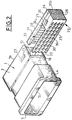
- Figure 1 is a perspective view of an electrical connector housing element, according to the invention.
- FIG 2 is a perspective view of the housing member of Figure 1, the locking key being assumed to be removed.
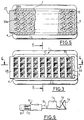
- Figure 3 is a front elevational view of the housing member, the key being in the pre-locked position.
- Figure 4 is a sectional view along line 4-4 of Figure 3.
- Figure 5 is a sectional view along line 5-5 of Figure 4.
- Figure 6 is a sectional view along line 6-6 of Figure 3.
- Figures 7 and 8 are enlarged views showing the key respectively in the pre-locking position and in the locking position.
- Figure 9 shows in elevation an electrical connection member for use with the housing element, according to the invention.
- the housing element shown in the figures comprises a body 1 of generally parallelepiped shape with two long sides 2 and 3 and two short sides 4 and 5.
- the body 1 On the side of one end 1 a , the body 1 has a series of channels 7, while on the side of the other end 1 b , said body is terminated by a skirt 8.
- Each channel 7 is intended to contain an electrical connection member 10 such as that shown in FIG. 9, this member has, at one end, a female part 11 with a clamp 12 intended to grip a male member and, at the other end, crimp tabs 13 intended to enclose a stripped end of a conductor and crimping lugs 14 intended to be crimped onto said conductor.
- the body 10 has a thinned part 15.
- the housing element on the side of its end opposite to the skirt 8, has grooves 17 on the internal face of the walls 2 and 3, while in an intermediate part of the body 1, across the channels 7, a slot 18.
- a housing 20 is formed and in the bottom of the housing, in the vicinity of the wall 2, extends a slot 19 which opens into two slots 22 and 23 formed in wall 2.
- a locking key 25 is provided and has a U shape to present a core 26 and two wings 27 and 28.
- the wing 27 is intended to be inserted into the slot 18 and comprises a series of holes 30 intended to coincide, each with a channel 7, each hole 30 having a part 30 a having a shape and a dimension corresponding to those of the female part 11, the members 10 and a notch 30 b having a dimension corresponding to that of the thinned part 15, said notches being offset angularly so that, when the key is engaged, that first the parts 30 a are located opposite the channels 7 and that at the end of insertion, the parts 30 b coincide with said channels 7.
- the wing 28, along each of its longitudinal edges, has a longitudinal projection 31 intended to cooperate with the corresponding groove 17, openings 33 being formed in said wing 28 and being intended to come into correspondence with channels 7.
- Each opening 33 has a section corresponding to that of a male member intended to engage in the part 11 of the female members 10, and is flared from the outer side of said wing 28.
- one of the edges of the wings 27 and 28 is connected by a cheek 34 having a projection 35 and a lug 36 with an inclined ramp 36 a terminated by a steep 36 b .
- this first position corresponds to a pre-locking in which the parts 30 has holes 30 coincide with the channels 7.
- the openings 33 are offset relative to the channels 7.
- the members 10 are placed in the channels 7 so as to abut against the wing 28 (see FIG. 4), then the key 25 is pushed towards the locking position (see FIG. 8) so that the projection 35 comes to be inserted in the light 23.
- the thinned parts 15 of the members 10 are housed in the notches 30 b , while the openings 33 coincide with the channels 7.
- the core 25 is inserted into the housing 20 so that the housing element can be engaged in a complementary element or in a support. If the key is not locked, the core 26 remains projecting so that the housing element cannot be put in place.
Landscapes
- Connector Housings Or Holding Contact Members (AREA)
- Details Of Connecting Devices For Male And Female Coupling (AREA)
Applications Claiming Priority (2)
| Application Number | Priority Date | Filing Date | Title |
|---|---|---|---|
| FR9402943A FR2717316B1 (fr) | 1994-03-14 | 1994-03-14 | Elément de boîtier de connecteur électrique. |
| FR9402943 | 1994-03-14 |
Publications (2)
| Publication Number | Publication Date |
|---|---|
| EP0673084A1 true EP0673084A1 (de) | 1995-09-20 |
| EP0673084B1 EP0673084B1 (de) | 1997-11-26 |
Family
ID=9461007
Family Applications (1)
| Application Number | Title | Priority Date | Filing Date |
|---|---|---|---|
| EP19950400516 Expired - Lifetime EP0673084B1 (de) | 1994-03-14 | 1995-03-10 | Gehäuseteil eines elektrischen Verbinders |
Country Status (4)
| Country | Link |
|---|---|
| EP (1) | EP0673084B1 (de) |
| DE (1) | DE69501088T2 (de) |
| ES (1) | ES2112019T3 (de) |
| FR (1) | FR2717316B1 (de) |
Cited By (10)
| Publication number | Priority date | Publication date | Assignee | Title |
|---|---|---|---|---|
| DE19532381A1 (de) * | 1995-09-01 | 1997-03-06 | Siemens Ag | Elektrischer Verbinder mit Kontaktsicherungsschieber |
| FR2739729A1 (fr) * | 1995-10-06 | 1997-04-11 | Cinch Connecteurs Sa | Element de boitier de connecteur electrique |
| DE19540247A1 (de) * | 1995-10-28 | 1997-04-30 | Delphi Automotive Systems Gmbh | Mehrpoliger elektrischer Steckverbinder |
| EP0822617A2 (de) * | 1996-07-31 | 1998-02-04 | Sumitomo Wiring Systems, Ltd. | Elektrischer Steckverbinder |
| EP0929124A1 (de) * | 1998-01-09 | 1999-07-14 | Sumitomo Wiring Systems, Ltd. | Elektrischer Verbinder |
| EP0978906A2 (de) * | 1998-08-03 | 2000-02-09 | Delphi Technologies, Inc. | Elektrischer Verbinder |
| DE19652624C2 (de) * | 1996-01-25 | 2002-02-28 | Connecteurs Cinch Montigny Le | Elektrischer Verbinder |
| EP2023443A3 (de) * | 2007-08-10 | 2010-06-30 | Itt Manufacturing Enterprises, Inc. | Steckeranschluss |
| EP2015406A3 (de) * | 2007-07-13 | 2010-07-14 | Tyco Electronics Japan G.K. | Elektrische Verbinderanordnung und Steckverbinder |
| WO2013027861A1 (en) * | 2011-08-23 | 2013-02-28 | Yazaki Corporation | Connector |
Families Citing this family (1)
| Publication number | Priority date | Publication date | Assignee | Title |
|---|---|---|---|---|
| DE10162589B4 (de) * | 2000-12-19 | 2005-09-01 | Sumitomo Wiring Systems, Ltd., Yokkaichi | Verbinder |
Citations (3)
| Publication number | Priority date | Publication date | Assignee | Title |
|---|---|---|---|---|
| DE3441559A1 (de) * | 1984-11-14 | 1986-05-22 | Adam Opel AG, 6090 Rüsselsheim | Steckverbindung |
| US5199902A (en) * | 1991-12-23 | 1993-04-06 | Gte Products Corporation | Connector device |
| GB2266415A (en) * | 1992-04-02 | 1993-10-27 | Orbital Engine | Clamp for conductors in connector |
-
1994
- 1994-03-14 FR FR9402943A patent/FR2717316B1/fr not_active Expired - Fee Related
-
1995
- 1995-03-10 EP EP19950400516 patent/EP0673084B1/de not_active Expired - Lifetime
- 1995-03-10 ES ES95400516T patent/ES2112019T3/es not_active Expired - Lifetime
- 1995-03-10 DE DE1995601088 patent/DE69501088T2/de not_active Expired - Fee Related
Patent Citations (3)
| Publication number | Priority date | Publication date | Assignee | Title |
|---|---|---|---|---|
| DE3441559A1 (de) * | 1984-11-14 | 1986-05-22 | Adam Opel AG, 6090 Rüsselsheim | Steckverbindung |
| US5199902A (en) * | 1991-12-23 | 1993-04-06 | Gte Products Corporation | Connector device |
| GB2266415A (en) * | 1992-04-02 | 1993-10-27 | Orbital Engine | Clamp for conductors in connector |
Cited By (21)
| Publication number | Priority date | Publication date | Assignee | Title |
|---|---|---|---|---|
| DE19532381C2 (de) * | 1995-09-01 | 1999-11-11 | Siemens Ag | Elektrischer Verbinder mit Kontaktsicherungsschieber |
| DE19532381A1 (de) * | 1995-09-01 | 1997-03-06 | Siemens Ag | Elektrischer Verbinder mit Kontaktsicherungsschieber |
| FR2739729A1 (fr) * | 1995-10-06 | 1997-04-11 | Cinch Connecteurs Sa | Element de boitier de connecteur electrique |
| US6234848B1 (en) | 1995-10-28 | 2001-05-22 | General Motors Corporation | Multipin electrical plug-in connector |
| DE19540247A1 (de) * | 1995-10-28 | 1997-04-30 | Delphi Automotive Systems Gmbh | Mehrpoliger elektrischer Steckverbinder |
| WO1997015962A2 (de) * | 1995-10-28 | 1997-05-01 | Delphi Automotive Systems Deutschland Gmbh | Mehrpoliger elektrischer steckverbinder |
| WO1997015962A3 (de) * | 1995-10-28 | 1997-06-12 | Delphi Automotive Systems Gmbh | Mehrpoliger elektrischer steckverbinder |
| DE19540247C2 (de) * | 1995-10-28 | 1999-11-04 | Delphi Automotive Systems Gmbh | Mehrpoliger elektrischer Steckverbinder |
| DE19652624C2 (de) * | 1996-01-25 | 2002-02-28 | Connecteurs Cinch Montigny Le | Elektrischer Verbinder |
| EP0822617A2 (de) * | 1996-07-31 | 1998-02-04 | Sumitomo Wiring Systems, Ltd. | Elektrischer Steckverbinder |
| EP0822617A3 (de) * | 1996-07-31 | 1999-02-10 | Sumitomo Wiring Systems, Ltd. | Elektrischer Steckverbinder |
| US5997364A (en) * | 1998-01-09 | 1999-12-07 | Sumitomo Wiring Systems, Ltd. | Electrical connector |
| EP0929124A1 (de) * | 1998-01-09 | 1999-07-14 | Sumitomo Wiring Systems, Ltd. | Elektrischer Verbinder |
| EP0978906A2 (de) * | 1998-08-03 | 2000-02-09 | Delphi Technologies, Inc. | Elektrischer Verbinder |
| EP0978906A3 (de) * | 1998-08-03 | 2003-09-03 | Delphi Technologies, Inc. | Elektrischer Verbinder |
| EP2015406A3 (de) * | 2007-07-13 | 2010-07-14 | Tyco Electronics Japan G.K. | Elektrische Verbinderanordnung und Steckverbinder |
| EP2023443A3 (de) * | 2007-08-10 | 2010-06-30 | Itt Manufacturing Enterprises, Inc. | Steckeranschluss |
| US7828606B2 (en) | 2007-08-10 | 2010-11-09 | Itt Manufacturing Enterprises, Inc. | Push lock connector |
| WO2013027861A1 (en) * | 2011-08-23 | 2013-02-28 | Yazaki Corporation | Connector |
| CN103765692A (zh) * | 2011-08-23 | 2014-04-30 | 矢崎总业株式会社 | 连接器 |
| KR101532186B1 (ko) * | 2011-08-23 | 2015-06-26 | 야자키 소교 가부시키가이샤 | 커넥터 |
Also Published As
| Publication number | Publication date |
|---|---|
| FR2717316A1 (fr) | 1995-09-15 |
| DE69501088D1 (de) | 1998-01-08 |
| FR2717316B1 (fr) | 1996-05-31 |
| EP0673084B1 (de) | 1997-11-26 |
| ES2112019T3 (es) | 1998-03-16 |
| DE69501088T2 (de) | 1998-03-19 |
Similar Documents
| Publication | Publication Date | Title |
|---|---|---|
| EP0658952B1 (de) | Elektrische Kontaktbuchse und Verbindergehäuse zur Aufnahme einer solchen Buchse | |
| EP0673084B1 (de) | Gehäuseteil eines elektrischen Verbinders | |
| FR2730585A1 (fr) | Connecteur electrique a grille de verrouillage de contacts et tiroir | |
| EP0859432A1 (de) | Weibliches elektrisches Kontaktorgan | |
| FR2730588A1 (fr) | Perfectionnements aux connecteurs electriques | |
| EP0723314B1 (de) | Elektrischer Verbinder | |
| EP0675565A1 (de) | Eindrückbare Steckverbinder und Anschlussleiste der mit diesen eindrückbare Steckverbinder ausgerüstet ist | |
| FR2702889A1 (fr) | Connecteur électrique . | |
| FR2706687A1 (fr) | Elément de boîtier de connecteur électrique. | |
| EP0581638B1 (de) | Elektrischer Verbinder | |
| EP0519815A1 (de) | Elektrischer Steckverbinder | |
| EP0292394B1 (de) | Elektrische Verbindung | |
| EP0660447A1 (de) | Verbesserungen an Gehäuseteilen von elektrischen Verbindern | |
| EP0544558A1 (de) | Elektrischer Steckverbinder mit Verriegelungshebel | |
| EP0814541B1 (de) | Elektrischer Verbinder | |
| FR2736756A1 (fr) | Connecteur electrique avec element de retenue de broches et contacts formant ponts | |
| FR2726403A1 (fr) | Connecteur electrique | |
| EP0642193A1 (de) | Schneidklemmverbinder | |
| FR2774816A1 (fr) | Element de boitier de connecteur electrique | |
| FR2777392A1 (fr) | Connecteur electrique | |
| FR2649251A1 (fr) | Organe de contact electrique femelle | |
| FR2747846A1 (fr) | Montage d'organes de contacts electriques dans des elements de boitiers de connecteurs electriques | |
| FR2535910A1 (fr) | Connecteur electrique | |
| FR2706688A1 (fr) | Elément modulaire destiné, avec d'autres éléments identiques, à constituer un élément de boîtier de connecteur électrique. | |
| FR2739729A1 (fr) | Element de boitier de connecteur electrique |
Legal Events
| Date | Code | Title | Description |
|---|---|---|---|
| PUAI | Public reference made under article 153(3) epc to a published international application that has entered the european phase |
Free format text: ORIGINAL CODE: 0009012 |
|
| AK | Designated contracting states |
Kind code of ref document: A1 Designated state(s): DE ES IT |
|
| 17P | Request for examination filed |
Effective date: 19960103 |
|
| GRAG | Despatch of communication of intention to grant |
Free format text: ORIGINAL CODE: EPIDOS AGRA |
|
| GRAH | Despatch of communication of intention to grant a patent |
Free format text: ORIGINAL CODE: EPIDOS IGRA |
|
| 17Q | First examination report despatched |
Effective date: 19970506 |
|
| GRAH | Despatch of communication of intention to grant a patent |
Free format text: ORIGINAL CODE: EPIDOS IGRA |
|
| GRAA | (expected) grant |
Free format text: ORIGINAL CODE: 0009210 |
|
| ITF | It: translation for a ep patent filed |
Owner name: PATRITO BREVETTI |
|
| AK | Designated contracting states |
Kind code of ref document: B1 Designated state(s): DE ES IT |
|
| REF | Corresponds to: |
Ref document number: 69501088 Country of ref document: DE Date of ref document: 19980108 |
|
| REG | Reference to a national code |
Ref country code: ES Ref legal event code: FG2A Ref document number: 2112019 Country of ref document: ES Kind code of ref document: T3 |
|
| PGFP | Annual fee paid to national office [announced via postgrant information from national office to epo] |
Ref country code: ES Payment date: 19980317 Year of fee payment: 4 |
|
| PGFP | Annual fee paid to national office [announced via postgrant information from national office to epo] |
Ref country code: DE Payment date: 19980319 Year of fee payment: 4 |
|
| PLBE | No opposition filed within time limit |
Free format text: ORIGINAL CODE: 0009261 |
|
| STAA | Information on the status of an ep patent application or granted ep patent |
Free format text: STATUS: NO OPPOSITION FILED WITHIN TIME LIMIT |
|
| 26N | No opposition filed | ||
| PG25 | Lapsed in a contracting state [announced via postgrant information from national office to epo] |
Ref country code: ES Free format text: THE PATENT HAS BEEN ANNULLED BY A DECISION OF A NATIONAL AUTHORITY Effective date: 19990311 |
|
| PG25 | Lapsed in a contracting state [announced via postgrant information from national office to epo] |
Ref country code: DE Free format text: LAPSE BECAUSE OF NON-PAYMENT OF DUE FEES Effective date: 20000101 |
|
| REG | Reference to a national code |
Ref country code: ES Ref legal event code: FD2A Effective date: 20010604 |
|
| PG25 | Lapsed in a contracting state [announced via postgrant information from national office to epo] |
Ref country code: IT Free format text: LAPSE BECAUSE OF NON-PAYMENT OF DUE FEES Effective date: 20050310 |