EP0672449B1 - Verfahren und Vorrichtung zum Aufschlämmen, Emulgieren und/oder Mahlen - Google Patents
Verfahren und Vorrichtung zum Aufschlämmen, Emulgieren und/oder Mahlen Download PDFInfo
- Publication number
- EP0672449B1 EP0672449B1 EP95810119A EP95810119A EP0672449B1 EP 0672449 B1 EP0672449 B1 EP 0672449B1 EP 95810119 A EP95810119 A EP 95810119A EP 95810119 A EP95810119 A EP 95810119A EP 0672449 B1 EP0672449 B1 EP 0672449B1
- Authority
- EP
- European Patent Office
- Prior art keywords
- grinding
- stirring
- rotation
- rotation axes
- location
- Prior art date
- Legal status (The legal status is an assumption and is not a legal conclusion. Google has not performed a legal analysis and makes no representation as to the accuracy of the status listed.)
- Expired - Lifetime
Links
Images
Classifications
-
- B—PERFORMING OPERATIONS; TRANSPORTING
- B01—PHYSICAL OR CHEMICAL PROCESSES OR APPARATUS IN GENERAL
- B01F—MIXING, e.g. DISSOLVING, EMULSIFYING OR DISPERSING
- B01F27/00—Mixers with rotary stirring devices in fixed receptacles; Kneaders
- B01F27/60—Mixers with rotary stirring devices in fixed receptacles; Kneaders with stirrers rotating about a horizontal or inclined axis
- B01F27/70—Mixers with rotary stirring devices in fixed receptacles; Kneaders with stirrers rotating about a horizontal or inclined axis with paddles, blades or arms
- B01F27/701—Mixers with rotary stirring devices in fixed receptacles; Kneaders with stirrers rotating about a horizontal or inclined axis with paddles, blades or arms comprising two or more shafts, e.g. in consecutive mixing chambers
- B01F27/702—Mixers with rotary stirring devices in fixed receptacles; Kneaders with stirrers rotating about a horizontal or inclined axis with paddles, blades or arms comprising two or more shafts, e.g. in consecutive mixing chambers with intermeshing paddles
Definitions
- the invention is in the fields of grinding and mixing technology and relates to a method and a device according to the preambles of the corresponding, independent claims for slurrying, emulsifying and / or grinding highly sensitive vegetable or animal, solid and / or liquid materials.
- slurries are used to denote a process in which from a mixture of solid parts and liquid while crushing the solid parts a macroscopically homogeneous slurry (porridge) is created.
- Emulsification is a process in which is called Areas of immiscible liquids a macroscopically homogeneous emulsion will be produced.
- the plant material is used alone with a high-speed Slicer, as used for mincing meat, fine crushed and the resulting chopped material for further processing, e.g. Fermentation or fermentation, mixed with the liquid.
- Man can also plant parts with a hand blender in a container directly below Process the addition of a liquid to a porridge.
- Another disadvantage is that high speeds, so high Tool speeds, the plant material locally heated and thereby the quality of the product may be affected.
- Emulsions are also made by crushing the drops of the various immiscible liquids with high-speed, often sharp tools manufactured using local heating, especially during processing of highly viscous and highly sensitive liquids, e.g. Protein, can also become a problem.
- a motor is also used powered mortar described in which in a rotating Grinding vessel (mortar bowl) a heavy grinding body (pestle) in the form of a There is a roller or a cone that rolls freely in the grinding vessel so that the material is crushed between the grinding vessel and the grinding media. With such a Mortar can be ground (ground) gently, but not slurried and be emulsified.
- the object of the invention is to demonstrate a method and to provide an apparatus for performing the method with which Mixtures consisting of solid parts and liquid consisting of solid Parts and several immiscible liquids or consisting of immiscible Liquids in one step to be as homogeneous as possible Slurries or emulsions can be processed with which but also solid substances can be ground.
- Method and device should be used particularly advantageously for highly sensitive materials.
- the sensitive components should not be caused by local heating come to harm.
- the fine structures are also to be processed in this way be as intensive an interaction as possible between the individual Parts of the materials to be processed becomes possible, so that for example completely dissolve soluble components in the liquid.
- the device according to the invention should be particularly advantageously applicable for gentle processing of highly sensitive, vegetable and animal Materials.
- the device according to the invention is intended further be designed such that they are largely independent of the container is in which the material to be machined is contained and that they are simply on different applications is customizable.
- the inventive method are rhythmically changing Grinding / stirring process on the solid parts or drops to be crushed of the material to be processed rhythmically pressing forces, deformation forces and shear forces are exerted, the force action being interrupted rhythmically becomes of dwell times in the liquid.
- the solid parts are crushed in a grinding manner, that is actually crushed, stretched and torn (not cut) while liquid, that adheres to the solid surfaces and / or in the solid parts has penetrated, is pressed with substances dissolved in it.
- the squeezed liquid is replaced and are crushed and tearing newly created surfaces and / or new accessible areas of the interior of the solid parts interacting with liquid brought.
- the device according to the invention is inspired by the natural process of chewing, as performed especially by cows ruminating becomes. Plants or parts of plants are between mating surfaces of the teeth that fit into one another pressed, ground and torn and mixed in the mouth with saliva. The plant material is not only macroscopically crushed but also microscopic structures are also opened up, so that for example Active ingredients and flavorings become accessible. It can be observed that the cow rhythmically performs this chewing process. You have to conclude that by switching between active chewing between teeth and relaxing movement in the mouth (e.g. through the tongue) is essential Contribution to the quality of the vegetable porridge is made. To this In the example of nature, a plant pulp of high quality becomes the next one Further processing (digestion) generated.
- the device according to the invention has rotating "teeth” (in the sense of blunt chewing teeth, like a cow's chewing teeth mentioned above) whose "Buying areas” interact rhythmically with each other while doing the required Apply forces to the material to be mixed and shredded. Due to the rotation, the “teeth” simultaneously provide a feed of the material between the “teeth” and for a thorough mixing of the “Teeth” surrounding material. An interaction between "teeth” and Vascular wall is not provided.
- the device according to the invention has at least two grinding / stirring bodies which rotate in opposite directions about two parallel axes and the surfaces of which form one or more self-contained grinding surfaces, which by the rotation movement in pairs with one another interact with the narrowing grinding point.
- the grinding / stirring body are designed, arranged and driven in pairs in such a way that the grinding surfaces of an interacting pair of grinding surfaces for feeding of the material to be processed in the same direction to the corresponding grinding point move against it so that the two grinding surfaces move in front of the grinding point Generation of pressing forces move against each other that to generate Deformation forces the one of the grinding surfaces in the area of the grinding point is concave and the other is convex and that to generate the shear forces two grinding surfaces in relation to the grinding point in the same direction but move at different speeds.
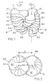
- Figure 1 shows a preferred embodiment of the device according to the invention.
- the device has two grinding / stirring bodies A and B, which are shown in their corresponding mutual arrangement.
- the two parallel axes of rotation X and Y with their directions of rotation are also shown. Since the mechanical design of the axes and their connection to a corresponding drive can be designed and implemented by a specialist without difficulty, these parts of the device are not shown.
- the relative rotation of the two grinding / stirring bodies A and B as seen by the two axes X and Y and the two directions of rotation are shown, can also be understood as rotation of the grinding / stirring body B around the Rotation axis X with simultaneous rotation of the body B around the rotation axis Y and with stationary body A.
- the rotation speeds around the axes X and Y are the same size regardless of the type of rotation to choose.
- the two grinding / stirring bodies A and B each consist of a plurality, for example six, grinding / stirring elements A.1-6 and B.1-6 all the same To have shape.
- the elements are disks with two parallel main surfaces H and H 'trained and have a two-fold axis of symmetry, the coincides with the axis of rotation (X or Y), i.e. each grinding / stirring element is with it after a rotation of 180 ° around the axis of rotation even congruent.
- the elements A.1-6 and the elements B.1-6 are arranged helically on the axis of rotation X or Y, the both screws have the same pitch but opposite turns exhibit.
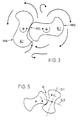
- FIG 2 shows the two grinding / stirring bodies A and B of Figure 1 as a plan view parallel to the axes of rotation. From this illustration is the grinding point formed by the grinding surfaces MA and MB of the grinding / stirring elements A.1 and B.1 in the current rotational position MS visible. Each additional pair of grinding / stirring elements also forms a grinding point.
- the width of the grinding point i.e. the distance between the two grinding surfaces MA and MB at the narrowest point, is given by the dimensions of the grinding / stirring elements and by the distance d between the axes of rotation X and Y. It can also depend on the position of rotation of the two elements . Given the grinding elements A.1 and B.1, the width of the grinding point can be varied by adjusting the distance d between the axes of rotation X and Y, means for such an adjustment being known per se and therefore not being shown.
- the slurry, Emulsification or grinding process for certain applications be adjusted.
- a grinding point width in each Case is larger than the diameter of granular parts of the processed Material it is possible that the crushing of such granular parts (e.g. Seeds) is prevented.
- the Distance d during the slurry or emulsification process this to the changing size of the solid parts during the process be continuously adjusted. This makes it possible that even rough Grains, for example, at the beginning of the grinding process (with a relatively wide grinding point or grinding points) are only slightly involved in the grinding process so that the load on the grinder is not jammed coarse parts between the grinding tools or in the grinding process resulting grinding pockets to a standstill.
- Figure 3 shows a pair A.1 / B.1 of the grinding / stirring elements of the grinding / stirring body according to Figures 1 and 2.
- arrows also indicate which movements and eddies the stirring effect of the rotating grinding / stirring elements in the surrounding Material created.
- the material to be processed is moved against and into the grinding point MS by the two grinding surfaces MA and MB moving from the same side (feed region E) against the grinding point. It can be seen that the movements generated in the material to be processed guarantee, on the one hand, a rhythmic alternation between passing through the grinding point MS (grinding phase) and recovery phase during a movement around the grinding / stirring elements and, on the other hand, are sufficient to ensure continuous homogenization even at relatively low rotational speeds of the material.
- the speeds of the grinding surfaces in the grinding point depend on the speed of rotation of the grinding media and the distances from the axes of rotation of the grinding surface positions forming the grinding point. This Speeds are related to the sensitivity of the material being processed adapt. Experiments have shown that in particular the difference the grinding surface speeds at the grinding point an important processing parameter is. Speed differences in the order of 0.3 to 1 m / sec have very good results for highly sensitive materials surrender.
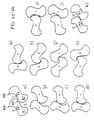
- FIGS. 4a to 4k now show a pair of grinding / stirring elements A.1 and B.1, as already described in connection with FIGS. 1 to 3, in various rotational positions during a full rotation of the two elements to illustrate the grinding process. It can be seen from the figure that a wide variety of grinding situations arise during one rotation of the grinding elements, in other words that for components of the material to be processed not only does a rhythmic alternation between the grinding phase and the recovery phase take place, but also a rhythmic change of the beginning mentioned pressing, crushing, deformation and shearing processes.
- the grinding surfaces (M, Fig. 1) askew to the main surfaces (H and H ', Fig 1) may be arranged. They are arrangements with more than two grinding / stirring elements conceivable, these in pairs with two parallel axes of rotation or arranged in groups of more than two bodies, the associated axes of rotation are parallel and equidistant and each body can interact with more than one other body.
- the grinding / stirring body does not stop individual grinding / stirring elements exist, but are in one piece and for example not a "step screw” ( Figure 1) but a continuous one Represent screw, but the cross section on each axial position of the Form of a grinding / stirring element according to Figure 3. Obviously the production of such a screw body but significantly more complex.
- the individual grinding / stirring elements spaced from each other on the axis of rotation and for example their main surfaces not or only partially perpendicular to the axis of rotation run.
- the main surfaces may be crooked or curved achieve an increased stirring effect.
- only the elements of a grinding / stirring body with spaced elements has crooked or curly major surfaces while the other body is designed as shown in Figures 1 and 2.
- FIG. 5 shows a further exemplary embodiment of a pair of grinding / stirring elements. It is a shape which not only has a two-fold axis of symmetry, like the embodiment according to FIGS. 1 to 5, but also two planes of symmetry S.1 and S.2. Considerations, as they were made in connection with FIGS. 4a to 4k, on such highly symmetrical grinding / stirring bodies or elements show that in the case of the mirror-symmetrical embodiment, the trough-shaped design of the feed area is less strong than in the case of an embodiment according to FIGS. 1 to 4, which slightly changes the grinding characteristics, especially their press aspect. In addition, in a mirror-symmetrical embodiment, the proportion of the grinding surfaces actively involved in the grinding process is reduced, which makes the grinding process somewhat less efficient.
Landscapes
- Chemical & Material Sciences (AREA)
- Chemical Kinetics & Catalysis (AREA)
- Crushing And Grinding (AREA)
- Disintegrating Or Milling (AREA)
- Mixers Of The Rotary Stirring Type (AREA)
Description
Dabei zeigen:
- Figur 1
- ein Paar von Mahl/Rührkörpern einer bevorzugten Ausführungsform der erfindungsgemässen Vorrichtung in perspektivischer Darstellung;
- Figur 2
- die beiden Mahl/Rührkörper der Ausführungsform gemäss Figur 1 als Draufsicht parallel zu den Rotationsachsen;
- Figur 3
- ein Paar von Mahl/Rührelementen der Ausführungsform gemäss Figur 1 als Draufsicht parallel zu den Rotationsachsen;
- Figuren 4a bis 4k
- das Paar von Mahl/Rührelementen der Figur 3 in verschiedenen Rotationspositionen;
- Figur 5
- eine weitere Ausführungsform von Mahl/Rührelementen.
- In der Phase a wird die Mahlstelle durch zwei konvexe Mahlflächen gebildet, sodass keine Deformationswirkung entsteht. Die Deformationswirkung nimmt bis zur Phase e zu und nimmt von Phase h an wieder ab.
- In der Phase a haben die beiden Mahlflächen etwa die gleiche Geschwindigkeit, sie üben also keine oder eine sehr kleine Scherwirkung aus. Die Scherwirkung nimmt bis zur Phase e zu und von Phase h an wieder ab. Das Maximum an Scherwirkung entsteht bei grösstem Unterschied der Abstände der Mahlstelle von den beiden Rotationsachsen, was bei der vorliegenden Ausführungsform einem Verhältnis von ca. 1:3 entspricht, und womit gute Resultate erzeugt worden sind.
- Zwischen den Phasen a und e wird im Einzugsbereich E der Mahlstelle eine Art Mahltasche kontinuierlich verengt, wodurch Presskräfte entstehen, die die Flüssigkeit langsam aus den festen Teilen des zu bearbeitenden Materials pressen.
- In Phase g erweitert sich die Mahlstelle vorübergehend, sodass sie von dem zu verarbeitenden Material oder von Flüssigkeit allein durchspühlt und so gereinigt wird.
Claims (10)
- Verfahren zum schonenden Aufschlämmen, Emulgieren und/oder Mahlen von hochempfindlichen, insbesondere pflanzlichen oder tierischen Materialien, in welchem Verfahren das zu verarbeitende Material bestehend aus festen Teilen, aus festen Teilen und einer Flüssigkeit, aus festen Teilen und mehreren nicht mischbaren Flüssigkeiten oder bestehend aus mehreren nicht mischbaren Flüssigkeiten mittels rotierenden Mahl/Rührkörpern gerührt und an einer sich verengenden Mahlstelle (MS) zwischen Bereichen von zwei in sich geschlossenen, um Rotationsachsen (X, Y) rotierenden Mahlflächen (MA, MB) bearbeitet wird,wobei zur Zuführung des zu bearbeitenden Materials zur Mahlstelle (MS) und zur Erzeugung von pressenden Kräften auf die Bestandteile des zu bearbeitenden Materials die zwei Mahlflächen (MA, MB) von der gleichen Seite und sich einander nähernd zur mindestens einen Mahlstelle (MS) bewegt werden,wobei zur Erzeugung scherender Kräfte auf die Bestandteile des zu bearbeitenden Materials die beiden Mahlflächen (MA, MB) mindestens zeitweise mit verschiedenen Geschwindigkeiten durch die Mahlstelle (MS) bewegt werden,wobei zur Erzeugung von deformierenden Kräften auf die Bestandteile des zu bearbeitenden Materials im Bereiche der Mahlstelle (MS) mindestens zeitweise die eine Mahlfläche konkav und die andere konvex ist,wobei das zu bearbeitende Material die rotierenden Mahlflächen (MA, MB) umgibt und durch diese senkrecht zu den Rotationsachsen (X, Y) bewegt wird,wobei die Bearbeitung durch die zuführenden, pressenden, scherenden und deformierenden Kräfte in einem Rhythmus sich ändernder Mahlphasen abläuftund wobei dieser Rhythmus in einer Mehrzahl von in Richtung der Rotationsachsen (X, Y) benachbarten Mahlstellen (MS) phasenverschoben ist, derart, dass das zu bearbeitende Material auch parallel zu den Rotationsachsen (X, Y) bewegt wird.
- Verfahren nach Anspruch 1, dadurch gekennzeichnet, dass durch Veränderung des Abstandes der Mahlflächen (MA, MB) an den Mahlstellen (MS) während dem Aufschlämmungs-, Emulgier- und/oder Mahlprozess die Bearbeitungskräfte verändert werden.
- Vorrichtung zum schonenden Aufschlämmen Emulgieren und/oder Mahlen von hochempfindlichen Materialien, insbesondere von pflanzlichen oder tierischen Materialien nach dem Verfahren gemäss Anspruch 1 oder 2, welche Vorrichtung mindestens zwei Mahl/Rührkörper (A, B) und keine an die Mahl/Rührkörper (A, B) angepasste Gefässwand aufweist,wobei die Mahl/Rührkörper (A, B) paarweise um zwei parallele Rotationsachsen (X, Y) in gegenläufigem Drehsinn rotierend antreibbar sind und ihre Oberflächen paarweise an einer Mahlstelle (MS) mahlend interagierende, in sich geschlossene Mahlflächen (MA, MB) aufweisen, die rotierende stumpfe Kauzähne bilden,wobei die Mahlflächen (MA, MB) der Mahl/Rührkörper (A, B) derart ausgebildet und relativ zueinander angeordnet sind, dass sie sich einander nähernd und in gleicher Richtung gegen die Mahlstelle bewegen und derart dass mindestens zeitweise zwei Mahlflächenbereiche mit verschiedenen Abständen von den Rotationsachsen (X, Y) und mindestens zeitweise ein konkaver und ein konvexer Mahlflächenbereich die mindestens eine Mahlstelle (MS) bilden,wobei die Mahlflächen (MA, MB) derart ausgebildet sind, dass durch die Rotation ein Rhythmus von verschiedenen Mahlphasen entstehtund wobei die Mahl/Rührkörper (A, B) schraubenförmig ausgebildet sind, derart, dass in Richtung der Rotationsachsen (X, Y) eine Mehrzahl von Mahlstellen (MS) entsteht, in welchen Mahlstellen (MS) der Rhythmus der Mahlphasen phasenverschoben abläuft.
- Vorrichtung nach Anspruch 3, dadurch gekennzeichnet, dass die Mahl/Rührkörper (A, B) aus einer Anzahl von gleichen Mahl/Rührelementen (A.1-6, B.1-6) besteht, die auf den Rotationsachsen (X, Y) schraubenförmig angeordnet sind, und dass die Mahlflächen (MA, MB) der Mahl/Rührelemente parallel zu den Rotationsachsen (X, Y) sind.
- Vorrichtung nach Anspruch 3 oder 4, dadurch gekennzeichnet, dass das Verhältnis zwischen maximalem Abstand von Mahlfläche (MA, MB)) und Rotationsachse (X, Y) und minimalem Abstand zwischen Mahlfläche und Rotationsachse an einem Mahl/Rührkörper (A, B) oder an einem Mahl/Rührelement 3:1 bis 2:1 beträgt.
- Vorrichtung nach einem der Ansprüche 3 bis 5, dadurch gekennzeichnet, dass Schnitte durch Mahl/Rührkörper (A, B) oder Mahl/Rührelemente (A.1-6, B.1-6) senkrecht zu den Rotationsachsen (X, Y) eine 2-zählige, mit der Rotationsachse zusammenfallende Symmetrieachse aufweisen.
- Vorrichtung nach Anspruch 6, dadurch gekennzeichnet, dass die Schnitte durch Mahl/Rührkörper (A, B) oder Mahl/Rührelemente (A.1-6, B.1-6) senkrecht zu den Rotationsachsen (X, Y) zwei Symmetrieebenen (S.1, S.2) aufweisen.
- Vorrichtung nach einem der Ansprüche 3 bis 7, dadurch gekennzeichnet, dass jeder der Mahl/Rührkörper (A, B) eines Paares um je eine Rotationsachse (X, Y) rotierend antreibbar ist.
- Vorrichtung nach einem der Ansprüche 3 bis 7, dadurch gekennzeichnet, dass von einem Paar von Mahl/Rührkörpern (A, B) der eine stationär ist und der andere um den einen und um sich selbst rotierend antreibbar ist.
- Vorrichtung nach einem der Ansprüche 3 bis 9, dadurch gekennzeichnet, dass der Abstand (d) zwischen den Rotationsachsen (X, Y) einstellbar ist.
Applications Claiming Priority (3)
| Application Number | Priority Date | Filing Date | Title |
|---|---|---|---|
| CH790/94 | 1994-03-17 | ||
| CH79094 | 1994-03-17 | ||
| CH00790/94A CH688026A5 (de) | 1994-03-17 | 1994-03-17 | Verfahren und Vorrichtung zum Aufschlaemmen, Emulgieren und/oder Mahlen. |
Publications (2)
| Publication Number | Publication Date |
|---|---|
| EP0672449A1 EP0672449A1 (de) | 1995-09-20 |
| EP0672449B1 true EP0672449B1 (de) | 2000-09-06 |
Family
ID=4195248
Family Applications (1)
| Application Number | Title | Priority Date | Filing Date |
|---|---|---|---|
| EP95810119A Expired - Lifetime EP0672449B1 (de) | 1994-03-17 | 1995-02-22 | Verfahren und Vorrichtung zum Aufschlämmen, Emulgieren und/oder Mahlen |
Country Status (4)
| Country | Link |
|---|---|
| EP (1) | EP0672449B1 (de) |
| AT (1) | ATE196103T1 (de) |
| CH (1) | CH688026A5 (de) |
| DE (1) | DE59508694D1 (de) |
Families Citing this family (3)
| Publication number | Priority date | Publication date | Assignee | Title |
|---|---|---|---|---|
| JP6081137B2 (ja) * | 2012-10-22 | 2017-02-15 | 株式会社新日南 | 混練装置 |
| CN111972467B (zh) * | 2020-06-30 | 2022-11-11 | 泉州职业技术大学 | 一种食用肉泥加工装置 |
| CN114053936A (zh) * | 2021-11-23 | 2022-02-18 | 浙江锦丰新材料科技有限公司 | 一种涂料的混合装置及混合方法 |
Family Cites Families (8)
| Publication number | Priority date | Publication date | Assignee | Title |
|---|---|---|---|---|
| BE410149A (de) * | ||||
| DE239974C (de) * | ||||
| BE332265A (de) * | ||||
| GB595261A (en) * | 1944-12-07 | 1947-12-01 | Sydney Laurence Goodchild | Improvements in or relating to mixing machines |
| DE411741C (de) * | 1923-05-21 | 1925-04-03 | Drying Systems Inc | Vorrichtung zur Erzeugung eines Gemisches aus Luft und fluessigem Brennstoff zur Speisung von Brennern |
| US3831906A (en) * | 1972-11-09 | 1974-08-27 | Crepaco | Ingredient dispersing apparatus |
| US4556324A (en) * | 1984-05-01 | 1985-12-03 | E. I. Du Pont De Nemours And Company | Apparatus for forming films of constant thickness |
| AT389242B (de) * | 1987-03-26 | 1989-11-10 | Noricum Maschinenbau Handel | Einrichtung zum zerkleinern von material |
-
1994
- 1994-03-17 CH CH00790/94A patent/CH688026A5/de not_active IP Right Cessation
-
1995
- 1995-02-22 DE DE59508694T patent/DE59508694D1/de not_active Expired - Lifetime
- 1995-02-22 EP EP95810119A patent/EP0672449B1/de not_active Expired - Lifetime
- 1995-02-22 AT AT95810119T patent/ATE196103T1/de active
Also Published As
| Publication number | Publication date |
|---|---|
| DE59508694D1 (de) | 2000-10-12 |
| ATE196103T1 (de) | 2000-09-15 |
| CH688026A5 (de) | 1997-04-30 |
| EP0672449A1 (de) | 1995-09-20 |
Similar Documents
| Publication | Publication Date | Title |
|---|---|---|
| DE3990873C2 (de) | Verfahren und Vorrichtung zum Zerhacken, Feinzerkleinern und Mischen von gefrorenen Rohmaterial, wieTierfleisch, Fischfleisch und Bohnen | |
| EP2285476B1 (de) | Rotor-stator-system und verfahren zum herstellen von dispersionen | |
| DE1808969A1 (de) | Mischmaschine | |
| DE2534294A1 (de) | Verfahren zur kontinuierlichen zerkleinerung und aufbereitung von weichen pflanzlichen nahrungsmitteln | |
| DE2616155A1 (de) | Nassmahlvorrichtung | |
| DE2412765A1 (de) | Messer fuer speiseaufbereitungsmaschine | |
| EP0657218B1 (de) | Vorrichtung zum Schneiden von Fleisch | |
| DE3728710C2 (de) | Mischer zum Mischen von Feststoffschüttungen | |
| EP3473107B1 (de) | Vorrichtung und verfahren zum be- und verarbeiten von schokolade sowie verwendung einer universalmaschine dafür | |
| DE602006000775T2 (de) | Homogenisierender Mischer | |
| EP0487772B1 (de) | Verfahren und Vorrichtung zum Aufbereiten von Fleisch | |
| EP0377161B1 (de) | Verfahren und Vorrichtung zur Aufarbeitung von Restteig zu Neuteig | |
| DE3049915A1 (en) | Apparatus for disintegrating and mixing foodstuffs | |
| EP0672449B1 (de) | Verfahren und Vorrichtung zum Aufschlämmen, Emulgieren und/oder Mahlen | |
| EP0124137A2 (de) | Vorrichtung und Verfahren zur Zerkleinerung von Pflanzengut | |
| EP0648537A1 (de) | Vorrichtung zum Dispergieren von fliessfähigen Material-Gemischen | |
| DE408594C (de) | Verfahren zur Herstellung von Viskose | |
| CH355770A (de) | Verfahren und Apparatur zur kontinuierlichen oder chargenweisen Behandlung von Stoffen und Stoffgemischen | |
| DE970255C (de) | Vorrichtung zum Mischen von Stoffen | |
| DE3317613A1 (de) | Verfahren zur behandlung von ausgangsmaterialien fuer brot, gebaeck oder dergleichen | |
| DE4341568C1 (de) | Vorrichtung zur Zerkleinerung von organischen Massen | |
| EP3011878A1 (de) | Verfahren und küchenmaschine zum zubereiten eines zubereitungsguts | |
| DE865521C (de) | Haushaltmaschine mit fluegelartigem Werkzeug zum Zerkleinern, Mischen, Ruehren, Verschaeumen, Koagulieren und Durchlueften von Nahrungs- und Genussmitteln | |
| DE3301551A1 (de) | Einrichtung zum zerkleinern und fermentieren von restbrot | |
| DE1632455A1 (de) | Kunststoffmischer mit Zerkleinerungseinrichtung |
Legal Events
| Date | Code | Title | Description |
|---|---|---|---|
| PUAI | Public reference made under article 153(3) epc to a published international application that has entered the european phase |
Free format text: ORIGINAL CODE: 0009012 |
|
| AK | Designated contracting states |
Kind code of ref document: A1 Designated state(s): AT BE CH DE DK ES FR GB GR IE IT LI LU MC NL PT SE |
|
| 17P | Request for examination filed |
Effective date: 19960301 |
|
| 17Q | First examination report despatched |
Effective date: 19980505 |
|
| GRAG | Despatch of communication of intention to grant |
Free format text: ORIGINAL CODE: EPIDOS AGRA |
|
| 17Q | First examination report despatched |
Effective date: 19980505 |
|
| GRAG | Despatch of communication of intention to grant |
Free format text: ORIGINAL CODE: EPIDOS AGRA |
|
| GRAH | Despatch of communication of intention to grant a patent |
Free format text: ORIGINAL CODE: EPIDOS IGRA |
|
| GRAH | Despatch of communication of intention to grant a patent |
Free format text: ORIGINAL CODE: EPIDOS IGRA |
|
| GRAA | (expected) grant |
Free format text: ORIGINAL CODE: 0009210 |
|
| AK | Designated contracting states |
Kind code of ref document: B1 Designated state(s): AT BE CH DE DK ES FR GB GR IE IT LI LU MC NL PT SE |
|
| PG25 | Lapsed in a contracting state [announced via postgrant information from national office to epo] |
Ref country code: NL Free format text: LAPSE BECAUSE OF FAILURE TO SUBMIT A TRANSLATION OF THE DESCRIPTION OR TO PAY THE FEE WITHIN THE PRESCRIBED TIME-LIMIT Effective date: 20000906 Ref country code: GR Free format text: LAPSE BECAUSE OF NON-PAYMENT OF DUE FEES Effective date: 20000906 Ref country code: ES Free format text: THE PATENT HAS BEEN ANNULLED BY A DECISION OF A NATIONAL AUTHORITY Effective date: 20000906 |
|
| REF | Corresponds to: |
Ref document number: 196103 Country of ref document: AT Date of ref document: 20000915 Kind code of ref document: T |
|
| REG | Reference to a national code |
Ref country code: CH Ref legal event code: EP |
|
| REF | Corresponds to: |
Ref document number: 59508694 Country of ref document: DE Date of ref document: 20001012 |
|
| REG | Reference to a national code |
Ref country code: IE Ref legal event code: FG4D Free format text: GERMAN |
|
| ITF | It: translation for a ep patent filed | ||
| PG25 | Lapsed in a contracting state [announced via postgrant information from national office to epo] |
Ref country code: SE Free format text: LAPSE BECAUSE OF FAILURE TO SUBMIT A TRANSLATION OF THE DESCRIPTION OR TO PAY THE FEE WITHIN THE PRESCRIBED TIME-LIMIT Effective date: 20001206 Ref country code: PT Free format text: LAPSE BECAUSE OF FAILURE TO SUBMIT A TRANSLATION OF THE DESCRIPTION OR TO PAY THE FEE WITHIN THE PRESCRIBED TIME-LIMIT Effective date: 20001206 Ref country code: DK Free format text: LAPSE BECAUSE OF FAILURE TO SUBMIT A TRANSLATION OF THE DESCRIPTION OR TO PAY THE FEE WITHIN THE PRESCRIBED TIME-LIMIT Effective date: 20001206 |
|
| ET | Fr: translation filed | ||
| GBT | Gb: translation of ep patent filed (gb section 77(6)(a)/1977) |
Effective date: 20001206 |
|
| NLV1 | Nl: lapsed or annulled due to failure to fulfill the requirements of art. 29p and 29m of the patents act | ||
| PG25 | Lapsed in a contracting state [announced via postgrant information from national office to epo] |
Ref country code: LU Free format text: LAPSE BECAUSE OF NON-PAYMENT OF DUE FEES Effective date: 20010222 |
|
| PG25 | Lapsed in a contracting state [announced via postgrant information from national office to epo] |
Ref country code: MC Free format text: LAPSE BECAUSE OF NON-PAYMENT OF DUE FEES Effective date: 20010228 Ref country code: BE Free format text: LAPSE BECAUSE OF NON-PAYMENT OF DUE FEES Effective date: 20010228 |
|
| PG25 | Lapsed in a contracting state [announced via postgrant information from national office to epo] |
Ref country code: IE Free format text: LAPSE BECAUSE OF NON-PAYMENT OF DUE FEES Effective date: 20010419 |
|
| REG | Reference to a national code |
Ref country code: IE Ref legal event code: FD4D |
|
| PLBE | No opposition filed within time limit |
Free format text: ORIGINAL CODE: 0009261 |
|
| STAA | Information on the status of an ep patent application or granted ep patent |
Free format text: STATUS: NO OPPOSITION FILED WITHIN TIME LIMIT |
|
| 26N | No opposition filed | ||
| BERE | Be: lapsed |
Owner name: CERES HEILMITTEL A.G. Effective date: 20010228 |
|
| REG | Reference to a national code |
Ref country code: GB Ref legal event code: IF02 |
|
| REG | Reference to a national code |
Ref country code: CH Ref legal event code: NV Representative=s name: FREI PATENTANWALTSBUERO |
|
| PGFP | Annual fee paid to national office [announced via postgrant information from national office to epo] |
Ref country code: GB Payment date: 20030206 Year of fee payment: 9 |
|
| PG25 | Lapsed in a contracting state [announced via postgrant information from national office to epo] |
Ref country code: GB Free format text: LAPSE BECAUSE OF NON-PAYMENT OF DUE FEES Effective date: 20040222 |
|
| GBPC | Gb: european patent ceased through non-payment of renewal fee |
Effective date: 20040222 |
|
| PG25 | Lapsed in a contracting state [announced via postgrant information from national office to epo] |
Ref country code: IT Free format text: LAPSE BECAUSE OF NON-PAYMENT OF DUE FEES;WARNING: LAPSES OF ITALIAN PATENTS WITH EFFECTIVE DATE BEFORE 2007 MAY HAVE OCCURRED AT ANY TIME BEFORE 2007. THE CORRECT EFFECTIVE DATE MAY BE DIFFERENT FROM THE ONE RECORDED. Effective date: 20050222 |
|
| PGFP | Annual fee paid to national office [announced via postgrant information from national office to epo] |
Ref country code: CH Payment date: 20140116 Year of fee payment: 20 Ref country code: DE Payment date: 20140219 Year of fee payment: 20 |
|
| PGFP | Annual fee paid to national office [announced via postgrant information from national office to epo] |
Ref country code: AT Payment date: 20140212 Year of fee payment: 20 Ref country code: FR Payment date: 20140219 Year of fee payment: 20 |
|
| REG | Reference to a national code |
Ref country code: DE Ref legal event code: R071 Ref document number: 59508694 Country of ref document: DE |
|
| REG | Reference to a national code |
Ref country code: CH Ref legal event code: PL |
|
| REG | Reference to a national code |
Ref country code: AT Ref legal event code: MK07 Ref document number: 196103 Country of ref document: AT Kind code of ref document: T Effective date: 20150222 |