EP0670037B1 - Joints - Google Patents
Joints Download PDFInfo
- Publication number
- EP0670037B1 EP0670037B1 EP93923595A EP93923595A EP0670037B1 EP 0670037 B1 EP0670037 B1 EP 0670037B1 EP 93923595 A EP93923595 A EP 93923595A EP 93923595 A EP93923595 A EP 93923595A EP 0670037 B1 EP0670037 B1 EP 0670037B1
- Authority
- EP
- European Patent Office
- Prior art keywords
- gasket
- joint
- responsive elements
- responsive
- elements
- Prior art date
- Legal status (The legal status is an assumption and is not a legal conclusion. Google has not performed a legal analysis and makes no representation as to the accuracy of the status listed.)
- Expired - Lifetime
Links
- 239000000463 material Substances 0.000 claims abstract description 6
- 230000000295 complement effect Effects 0.000 claims description 4
- 239000012530 fluid Substances 0.000 abstract description 2
- 230000000694 effects Effects 0.000 description 1
- 238000009434 installation Methods 0.000 description 1
- 238000000034 method Methods 0.000 description 1
- 238000007789 sealing Methods 0.000 description 1
Images



Classifications
-
- G—PHYSICS
- G01—MEASURING; TESTING
- G01L—MEASURING FORCE, STRESS, TORQUE, WORK, MECHANICAL POWER, MECHANICAL EFFICIENCY, OR FLUID PRESSURE
- G01L5/00—Apparatus for, or methods of, measuring force, work, mechanical power, or torque, specially adapted for specific purposes
- G01L5/24—Apparatus for, or methods of, measuring force, work, mechanical power, or torque, specially adapted for specific purposes for determining value of torque or twisting moment for tightening a nut or other member which is similarly stressed
-
- F—MECHANICAL ENGINEERING; LIGHTING; HEATING; WEAPONS; BLASTING
- F16—ENGINEERING ELEMENTS AND UNITS; GENERAL MEASURES FOR PRODUCING AND MAINTAINING EFFECTIVE FUNCTIONING OF MACHINES OR INSTALLATIONS; THERMAL INSULATION IN GENERAL
- F16B—DEVICES FOR FASTENING OR SECURING CONSTRUCTIONAL ELEMENTS OR MACHINE PARTS TOGETHER, e.g. NAILS, BOLTS, CIRCLIPS, CLAMPS, CLIPS OR WEDGES; JOINTS OR JOINTING
- F16B31/00—Screwed connections specially modified in view of tensile load; Break-bolts
- F16B31/02—Screwed connections specially modified in view of tensile load; Break-bolts for indicating the attainment of a particular tensile load or limiting tensile load
-
- G—PHYSICS
- G01—MEASURING; TESTING
- G01L—MEASURING FORCE, STRESS, TORQUE, WORK, MECHANICAL POWER, MECHANICAL EFFICIENCY, OR FLUID PRESSURE
- G01L23/00—Devices or apparatus for measuring or indicating or recording rapid changes, such as oscillations, in the pressure of steam, gas, or liquid; Indicators for determining work or energy of steam, internal-combustion, or other fluid-pressure engines from the condition of the working fluid
- G01L23/08—Devices or apparatus for measuring or indicating or recording rapid changes, such as oscillations, in the pressure of steam, gas, or liquid; Indicators for determining work or energy of steam, internal-combustion, or other fluid-pressure engines from the condition of the working fluid operated electrically
- G01L23/18—Devices or apparatus for measuring or indicating or recording rapid changes, such as oscillations, in the pressure of steam, gas, or liquid; Indicators for determining work or energy of steam, internal-combustion, or other fluid-pressure engines from the condition of the working fluid operated electrically by resistance strain gauges
-
- F—MECHANICAL ENGINEERING; LIGHTING; HEATING; WEAPONS; BLASTING
- F16—ENGINEERING ELEMENTS AND UNITS; GENERAL MEASURES FOR PRODUCING AND MAINTAINING EFFECTIVE FUNCTIONING OF MACHINES OR INSTALLATIONS; THERMAL INSULATION IN GENERAL
- F16B—DEVICES FOR FASTENING OR SECURING CONSTRUCTIONAL ELEMENTS OR MACHINE PARTS TOGETHER, e.g. NAILS, BOLTS, CIRCLIPS, CLAMPS, CLIPS OR WEDGES; JOINTS OR JOINTING
- F16B31/00—Screwed connections specially modified in view of tensile load; Break-bolts
- F16B31/02—Screwed connections specially modified in view of tensile load; Break-bolts for indicating the attainment of a particular tensile load or limiting tensile load
- F16B2031/022—Screwed connections specially modified in view of tensile load; Break-bolts for indicating the attainment of a particular tensile load or limiting tensile load using an ultrasonic transducer
-
- Y—GENERAL TAGGING OF NEW TECHNOLOGICAL DEVELOPMENTS; GENERAL TAGGING OF CROSS-SECTIONAL TECHNOLOGIES SPANNING OVER SEVERAL SECTIONS OF THE IPC; TECHNICAL SUBJECTS COVERED BY FORMER USPC CROSS-REFERENCE ART COLLECTIONS [XRACs] AND DIGESTS
- Y10—TECHNICAL SUBJECTS COVERED BY FORMER USPC
- Y10S—TECHNICAL SUBJECTS COVERED BY FORMER USPC CROSS-REFERENCE ART COLLECTIONS [XRACs] AND DIGESTS
- Y10S285/00—Pipe joints or couplings
- Y10S285/91—Gaskets
Definitions
- the present invention is concerned with joints and, in particular joints having gaskets between complementary faces thereof.
- a gasket As is well known, the purpose of a gasket is to seal a joint. There are many methods of sealing a joint but the most common way is by employing bolts extending perpendicular to the joint to exert pressure on the gasket. The pressure exerted within the gasket must exceed the pressure within the system, or else the gasket will not perform its function and therefore whatever the gasket is trying to contain will inevitably escape.
- a problem with the use of bolts to cause components to engage on the face of a gasket is that the bolts are tightened individually, with the inevitable effect that the applied torque, and therefore the resulting force, is not evenly distributed throughout the gasket, thus causing local variations in applied pressure around the gasket. For example, in the case where there are four bolts equispaced around a joint, the tightening of one bolt inevitably causes some distortion of the diametrically opposed bolt. It is thus difficult to achieve equalised distribution of force.
- torque indicators can be used with the tightening spanners, these indicate the torque applied rather than the resultant force in the gasket.
- the present invention seeks to provide a joint in which such disadvantages can be at least alleviated.
- a joint comprising a first joint component having an axial aperture, a second joint component having an axial aperture arranged to be coaxial with the first mentioned aperture, a gasket arranged to be interposed between said components, and a plurality of bolts arranged to secure said first joint component to said second component with said gasket interposed therebetween with opposed faces in contact with respective joint components, wherein said gasket incorporates a plurality of stress or strain responsive elements substantially equispaced around the entire periphery of said gasket, each of said responsive elements comprising a pair of electrodes having a stress or strain responsive material sandwiched therebetween, each said responsive element having opposed faces which are spaced from the respective opposed faces of said gasket, and means for connecting each of said responsive elements to an output display so as to give detectable indication of the stress or strain applied to each individual one of said responsive elements corresponding to the torque force applied to a proximate bolt.
- the responsive elements therefore do not respond to the torque applied to the bolts, but to the force induced in the gasket during installation.
- the joint components are typically tubular members and the gasket is then annular.
- the responsive elements are encapsulated within the gasket.
- the responsive elements are encapsulated within the gasket.
- at least four equispaced responsive elements are provided.
- the gasket is provided with throughbores extending therethrough arranged to be complementary to throughbores provided for the bolts in said first and second joint components.
- the plurality of responsive elements are equal in number to the number of the plurality of bolts.
- the strain responsive elements are of the type suitable for inclusion in a strain gauge.
- the joint comprises a plurality of piezoelectric elements each comprising a pair of electrodes having a piezoelectric material sandwiched therebetween.
- the plurality of responsive elements is arranged around the entire periphery of the gasket such that a line drawn from the axis of said aperture radially outward through each bolt passes through a respective responsive element.
- first tubular component 1 having an inner face 2 and an outer face 3
- second tubular component 4 having an inner face 5 and an outer face 6.
- Inner faces 2 and 5 have a gasket ring 7 interposed therebetween to act as a fluid seal.
- a series of eight throughbores 8 are provided in tubular component 1 and a corresponding series of eight throughbores 9 are provided in tubular component 4.
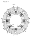
- Passing through each pair of throughbores 8 and 9 is a respective threaded bolt 10 (two only being shown in Figure 1, but as shown in Figure 3, there are generally at least four bolts).
- At one end of each bolt 10 is an internally threaded nut 11; at the other is an internally threaded nut 12.
- the two components 1, 4 can be urged closer together, with the gasket ring 7 interposed, by appropriate tightening of the nuts 11, 12.
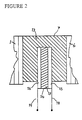
- the gasket ring 7 comprises gasket material 13 having at about the mid-plane of its thickness, a number of piezoelectric elements 14 each comprising a pair of electrodes 15 and 16 having sandwiched therebetween a piezoelectric material 17.
- the electrodes 15 and 16 are connected to respective lead wires 18, 19; when pressure is applied by means of the bolts, the pressure therefore acts directly on the top and bottom faces of the piezoelectric element 14 in the direction of arrows A, B shown in Figure 2, the pressure being transferred to the pressure fluctuation is produced in the piezoelectric element, and an output signal is therefore generated in lead wires 18, 19.
- the piezoelectric elements 14 may be equispaced around the circumference; for example, the embodiment of Figure 3 shows eight piezoelectric elements spaced around the gasket 7.
- the gasket may have apertures 20 therethrough, arranged to be complementary to the throughbores in the tubular components, such that bolts 10 can pass therethrough.
- Located within the gasket are various shapes of piezoelectric elements 21, each located in the proximity of the respective aperture 20.
- FIG 7 shows an alternative to Figure 2, in which like parts are denoted by like reference numerals.
- the piezoelectric element is within the body of the gasket and does not protrude from an edge.
Landscapes
- Physics & Mathematics (AREA)
- General Physics & Mathematics (AREA)
- Engineering & Computer Science (AREA)
- Chemical & Material Sciences (AREA)
- Combustion & Propulsion (AREA)
- General Engineering & Computer Science (AREA)
- Mechanical Engineering (AREA)
- Gasket Seals (AREA)
- Pharmaceuticals Containing Other Organic And Inorganic Compounds (AREA)
- Measuring Fluid Pressure (AREA)
- Force Measurement Appropriate To Specific Purposes (AREA)
- Pipeline Systems (AREA)
- Particle Formation And Scattering Control In Inkjet Printers (AREA)
- Measurement Of Length, Angles, Or The Like Using Electric Or Magnetic Means (AREA)
- Clamps And Clips (AREA)
Applications Claiming Priority (3)
| Application Number | Priority Date | Filing Date | Title |
|---|---|---|---|
| GB9223481 | 1992-11-10 | ||
| GB9223481A GB2272524B (en) | 1992-11-10 | 1992-11-10 | Joints |
| PCT/GB1993/002175 WO1994011718A1 (en) | 1992-11-10 | 1993-10-21 | Joints |
Publications (2)
| Publication Number | Publication Date |
|---|---|
| EP0670037A1 EP0670037A1 (en) | 1995-09-06 |
| EP0670037B1 true EP0670037B1 (en) | 1996-12-18 |
Family
ID=10724791
Family Applications (1)
| Application Number | Title | Priority Date | Filing Date |
|---|---|---|---|
| EP93923595A Expired - Lifetime EP0670037B1 (en) | 1992-11-10 | 1993-10-21 | Joints |
Country Status (16)
| Country | Link |
|---|---|
| US (1) | US5529346A (OSRAM) |
| EP (1) | EP0670037B1 (OSRAM) |
| JP (1) | JP3289108B2 (OSRAM) |
| KR (1) | KR100296945B1 (OSRAM) |
| CN (1) | CN1053961C (OSRAM) |
| AT (1) | ATE146589T1 (OSRAM) |
| AU (1) | AU672064B2 (OSRAM) |
| CA (1) | CA2147463C (OSRAM) |
| DE (1) | DE69306813T2 (OSRAM) |
| GB (1) | GB2272524B (OSRAM) |
| IN (1) | IN180486B (OSRAM) |
| MY (1) | MY111477A (OSRAM) |
| NO (1) | NO311109B1 (OSRAM) |
| NZ (1) | NZ257150A (OSRAM) |
| TW (1) | TW270167B (OSRAM) |
| WO (1) | WO1994011718A1 (OSRAM) |
Families Citing this family (42)
| Publication number | Priority date | Publication date | Assignee | Title |
|---|---|---|---|---|
| DE9320143U1 (de) * | 1993-12-30 | 1995-04-27 | Nord, Klaus Jürgen, 68199 Mannheim | Vorrichtung zum Steuern einer elektrischen Signaleinrichtung beim Auftreten unzulässiger Bewegungen von abgedichteten Wellen technischer Geräte |
| DE19527514C2 (de) * | 1995-07-27 | 1999-04-22 | Deutsch Zentr Luft & Raumfahrt | Schnittstelle für die Schwingungsreduktion in strukturdynamischen Systemen |
| GB2317701A (en) * | 1996-08-22 | 1998-04-01 | Vladimir Brnicevic | Seal with integral pressure sensor |
| US5925879A (en) * | 1997-05-09 | 1999-07-20 | Cidra Corporation | Oil and gas well packer having fiber optic Bragg Grating sensors for downhole insitu inflation monitoring |
| US5973317A (en) * | 1997-05-09 | 1999-10-26 | Cidra Corporation | Washer having fiber optic Bragg Grating sensors for sensing a shoulder load between components in a drill string |
| US5945665A (en) * | 1997-05-09 | 1999-08-31 | Cidra Corporation | Bolt, stud or fastener having an embedded fiber optic Bragg Grating sensor for sensing tensioning strain |
| US6175108B1 (en) | 1998-01-30 | 2001-01-16 | Cidra Corporation | Accelerometer featuring fiber optic bragg grating sensor for providing multiplexed multi-axis acceleration sensing |
| US6191414B1 (en) | 1998-06-05 | 2001-02-20 | Cidra Corporation | Composite form as a component for a pressure transducer |
| DE19826177B4 (de) * | 1998-06-13 | 2005-12-22 | Daimlerchrysler Ag | Verfahren und Vorrichtung zur aktiven Beeinflussung und Dämmung von Schwingungen, die von einem zumindest mittelbar motorisch angetriebenen Fahrzeug ausgehen |
| US6233374B1 (en) | 1999-06-04 | 2001-05-15 | Cidra Corporation | Mandrel-wound fiber optic pressure sensor |
| US6601671B1 (en) | 2000-07-10 | 2003-08-05 | Weatherford/Lamb, Inc. | Method and apparatus for seismically surveying an earth formation in relation to a borehole |
| US6739183B1 (en) * | 2002-02-15 | 2004-05-25 | Dana Corporation | Multiple-layer cylinder head gasket with integral pressure sensor apparatus for measuring pressures within engine cylinders |
| WO2003071119A2 (en) * | 2002-02-15 | 2003-08-28 | Dana Corporation | Apparatus for measuring pressures in engine cylinders |
| US7111505B2 (en) * | 2002-02-15 | 2006-09-26 | Dana Corporation | Multi-layer steel cylinder head gasket with integrated pressure sensor |
| US6957574B2 (en) * | 2003-05-19 | 2005-10-25 | Weatherford/Lamb, Inc. | Well integrity monitoring system |
| US6840114B2 (en) * | 2003-05-19 | 2005-01-11 | Weatherford/Lamb, Inc. | Housing on the exterior of a well casing for optical fiber sensors |
| DE102004025135B4 (de) * | 2004-05-17 | 2006-04-20 | Pt-Poly-Tec Gmbh Vertrieb Und Herstellung Von Dichtsystemen | Verfahren und Anordnung zur Leckagevorwarnung und Bauteilpositionierungsanzeige bei Muffenverbindungen |
| US20070193361A1 (en) * | 2006-02-20 | 2007-08-23 | Davie/Coffee Technologies, LLC | Compressive load sensor by capacitive measurement |
| JP4699935B2 (ja) * | 2006-04-26 | 2011-06-15 | 株式会社日立エンジニアリング・アンド・サービス | フランジ締結監視装置 |
| US20100320755A1 (en) * | 2007-06-26 | 2010-12-23 | Swagelok Company | Apparatus and method of zero clearance connection with optional sensing function |
| US20190271419A1 (en) * | 2007-06-26 | 2019-09-05 | Swagelok Company | Conduit connection with sensor |
| ES2629101T3 (es) * | 2008-05-05 | 2017-08-07 | Kistler Holding Ag | Célula de carga |
| DE202008009317U1 (de) | 2008-07-11 | 2008-09-18 | Kempchen Leuna Gmbh | Dichtungsanordnung für eine Flanschverbindung |
| EP2766707A1 (en) | 2011-10-12 | 2014-08-20 | Saudi Arabian Oil Company | Method for determining stress in flexible joints by use of leveling means |
| KR101293984B1 (ko) | 2011-12-02 | 2013-08-07 | 현대자동차주식회사 | 스트레인게이지 타입의 힘-토크 센서 및 그 제조 방법 |
| KR101480384B1 (ko) | 2013-04-11 | 2015-01-09 | 한국기계연구원 | 일체형 자가 상태 감지 공기 구동 밸브 |
| JP2015141345A (ja) * | 2014-01-29 | 2015-08-03 | 日本バルカー工業株式会社 | フランジ締付け実習システム |
| US20150226249A1 (en) * | 2014-02-07 | 2015-08-13 | Barnes Group Inc. | Torque Retention Arrangement |
| KR102390780B1 (ko) | 2015-03-06 | 2022-04-25 | 스와겔로크 컴패니 | 커플링에서 변형 검출을 위한 시스템 및 방법 |
| JP6396241B2 (ja) * | 2015-03-17 | 2018-09-26 | 株式会社東芝 | 面圧計測システム |
| CN104747719A (zh) * | 2015-03-27 | 2015-07-01 | 苏州宝骅机械技术有限公司 | 一种密封面应力可感知的密封组件 |
| CN105466649A (zh) * | 2015-12-28 | 2016-04-06 | 苏州宝骅机械技术有限公司 | 一种压紧载荷可检测密封组件及其使用方法 |
| CN105605078B (zh) * | 2016-03-11 | 2018-07-13 | 大连理工大学 | 一种用于监测螺栓连接界面的智能垫片装置 |
| CN105909892B (zh) * | 2016-05-05 | 2018-06-08 | 武汉工程大学 | 一种基于垫片压缩回弹特性的法兰接头预紧力设计方法 |
| CN110651150B (zh) * | 2017-05-24 | 2022-01-28 | 株式会社华尔卡 | 密封件的施工监视装置、施工监视程序、施工监视方法、施工监视系统以及施工实习系统 |
| CN108469326B (zh) * | 2018-02-28 | 2020-08-25 | 北京电子工程总体研究所 | 一种微力螺旋测量装置及系统 |
| RU2702456C1 (ru) * | 2018-09-12 | 2019-10-08 | Общество с ограниченной ответственностью "Силур" | Интеллектуальное уплотнение для контроля состояния разъемных соединений |
| RU2738289C2 (ru) * | 2018-09-28 | 2020-12-11 | Василий Мотелевич Оснач | Прокладка-уплотнитель, передающая информацию о своем состоянии |
| RU2695179C1 (ru) * | 2018-10-10 | 2019-07-22 | Акционерное общество "Научно-производственное объединение "СПЛАВ" (АО "НПО "СПЛАВ") | Уплотнительная прокладка для фланцевого соединения |
| RU188644U1 (ru) * | 2018-10-10 | 2019-04-18 | Акционерное общество "Научно-производственное объединение "СПЛАВ" (АО "НПО "СПЛАВ") | Уплотнительная прокладка для фланцевого соединения |
| US20210208018A1 (en) * | 2019-12-04 | 2021-07-08 | Lgc Us Asset Holdings, Llc | Sensor-embedded gasket for real-time monitoring |
| CN111120482B (zh) * | 2020-01-16 | 2025-02-28 | 郑州大学 | 一种新型可监控的补偿式垫圈装置及监控方法 |
Family Cites Families (12)
| Publication number | Priority date | Publication date | Assignee | Title |
|---|---|---|---|---|
| US1569837A (en) * | 1920-03-26 | 1926-01-12 | Spicer Mfg Corp | Means for determining tension on bolts |
| US3151258A (en) * | 1960-12-10 | 1964-09-29 | Sonderegger Hans Conrad | Device for measuring the forces between components of an assembly |
| US3358257A (en) * | 1965-12-27 | 1967-12-12 | Lockheed Aircraft Corp | Force and moment transducer |
| DE3333285A1 (de) * | 1983-09-15 | 1985-04-18 | Robert Bosch Gmbh, 7000 Stuttgart | Einrichtung zum erfassen von kraeften, spannungen bzw. beschleunigungen an maschinen, geraeten oder dgl. |
| US4573351A (en) * | 1984-02-13 | 1986-03-04 | Litton Systems, Inc. | Hub moment sensor for a horizontal rotor aircraft |
| US4741231A (en) * | 1986-04-14 | 1988-05-03 | The Warner & Swasey Company | Tool force sensor and method of making same |
| IT1224487B (it) * | 1988-10-12 | 1990-10-04 | Polysens Spa | Trasduttore per la rivelazione di sforzi dinamici ed apparecchiatura di misurazione e o di controllo comprendente tale trasduttore |
| DE68919365T2 (de) * | 1989-07-14 | 1995-06-14 | Richard Paul Warren | Verfahren zum überwachen der dichtungskomprimierung während des spannens eines befestigungselementes. |
| DE4015109A1 (de) * | 1990-05-11 | 1991-11-14 | Lechler Elring Dichtungswerke | Zylinderkopfdichtung |
| JPH04231829A (ja) * | 1990-05-31 | 1992-08-20 | Kistler Instr Ag | 平行にされた円板測定要素及び集積増幅器を有する介在式力センサ |
| US5121929A (en) * | 1991-06-24 | 1992-06-16 | Fel-Pro Incorporated | Gasket with encased load sensor |
| US20110187651A1 (en) * | 2010-02-03 | 2011-08-04 | Honeywell International Inc. | Touch screen having adaptive input parameter |
-
1992
- 1992-11-10 GB GB9223481A patent/GB2272524B/en not_active Expired - Fee Related
-
1993
- 1993-10-21 US US08/428,159 patent/US5529346A/en not_active Expired - Lifetime
- 1993-10-21 AT AT93923595T patent/ATE146589T1/de not_active IP Right Cessation
- 1993-10-21 CA CA002147463A patent/CA2147463C/en not_active Expired - Fee Related
- 1993-10-21 NZ NZ257150A patent/NZ257150A/en not_active IP Right Cessation
- 1993-10-21 JP JP51181094A patent/JP3289108B2/ja not_active Expired - Fee Related
- 1993-10-21 WO PCT/GB1993/002175 patent/WO1994011718A1/en not_active Ceased
- 1993-10-21 AU AU53560/94A patent/AU672064B2/en not_active Ceased
- 1993-10-21 DE DE69306813T patent/DE69306813T2/de not_active Expired - Lifetime
- 1993-10-21 KR KR1019950701606A patent/KR100296945B1/ko not_active Expired - Fee Related
- 1993-10-21 EP EP93923595A patent/EP0670037B1/en not_active Expired - Lifetime
- 1993-10-22 TW TW082108834A patent/TW270167B/zh not_active IP Right Cessation
- 1993-11-08 MY MYPI93002340A patent/MY111477A/en unknown
- 1993-11-09 IN IN682CA1993 patent/IN180486B/en unknown
- 1993-11-10 CN CN93114863A patent/CN1053961C/zh not_active Expired - Fee Related
-
1995
- 1995-05-08 NO NO19951786A patent/NO311109B1/no not_active IP Right Cessation
Also Published As
| Publication number | Publication date |
|---|---|
| DE69306813T2 (de) | 1997-06-12 |
| IN180486B (OSRAM) | 1998-02-07 |
| AU5356094A (en) | 1994-06-08 |
| TW270167B (OSRAM) | 1996-02-11 |
| CA2147463A1 (en) | 1994-05-26 |
| KR100296945B1 (ko) | 2002-05-13 |
| GB2272524B (en) | 1994-11-09 |
| AU672064B2 (en) | 1996-09-19 |
| MY111477A (en) | 2000-06-30 |
| CN1089724A (zh) | 1994-07-20 |
| CN1053961C (zh) | 2000-06-28 |
| NZ257150A (en) | 1995-12-21 |
| GB2272524A (en) | 1994-05-18 |
| NO951786D0 (no) | 1995-05-08 |
| DE69306813D1 (de) | 1997-01-30 |
| NO951786L (no) | 1995-05-08 |
| ATE146589T1 (de) | 1997-01-15 |
| GB9223481D0 (en) | 1992-12-23 |
| NO311109B1 (no) | 2001-10-08 |
| KR950704674A (ko) | 1995-11-20 |
| WO1994011718A1 (en) | 1994-05-26 |
| JPH08506166A (ja) | 1996-07-02 |
| JP3289108B2 (ja) | 2002-06-04 |
| US5529346A (en) | 1996-06-25 |
| CA2147463C (en) | 2004-04-20 |
| EP0670037A1 (en) | 1995-09-06 |
Similar Documents
| Publication | Publication Date | Title |
|---|---|---|
| AU672064B2 (en) | Joints | |
| US4888990A (en) | Sight glass apparatus | |
| US4573362A (en) | Multi-axis load transducer | |
| US5362115A (en) | Multi-ring gasket | |
| DE69011551T2 (de) | Konsumdirektdrucksensoreinheit. | |
| CA1053112A (en) | Preassembled pressure relief apparatus | |
| US2197450A (en) | Pipe coupling | |
| US11867327B2 (en) | Fluid-tight fitting | |
| US5458003A (en) | Electromagnetic flow meter | |
| SE459038B (sv) | Skarv foer hoegtrycksroerledning | |
| US4427222A (en) | Device for the tight joining of two parts | |
| US3399564A (en) | Load cell | |
| US4142744A (en) | Method and apparatus for coupling tubular members | |
| JPH0336799Y2 (OSRAM) | ||
| JPH0632554Y2 (ja) | フランジ接合部の応急修理装置 | |
| US4183688A (en) | Expansible sleeve deforms hub bore against shaft | |
| JPH0140374Y2 (OSRAM) | ||
| US4958856A (en) | Pressure energized sealing joint | |
| GB1585366A (en) | Method for the connection of glass parts | |
| SU1373939A1 (ru) | Уплотнение соединени в арматуре и сосудах высокого давлени | |
| JPS622026A (ja) | ロツク装置 | |
| JPS597878B2 (ja) | 急速着脱形継手 | |
| JPH07197926A (ja) | ねじの締忘れ防止法 |
Legal Events
| Date | Code | Title | Description |
|---|---|---|---|
| PUAI | Public reference made under article 153(3) epc to a published international application that has entered the european phase |
Free format text: ORIGINAL CODE: 0009012 |
|
| 17P | Request for examination filed |
Effective date: 19950530 |
|
| AK | Designated contracting states |
Kind code of ref document: A1 Designated state(s): AT BE CH DE DK ES FR GR IE IT LI LU NL PT SE |
|
| 17Q | First examination report despatched |
Effective date: 19951120 |
|
| GRAH | Despatch of communication of intention to grant a patent |
Free format text: ORIGINAL CODE: EPIDOS IGRA |
|
| GRAH | Despatch of communication of intention to grant a patent |
Free format text: ORIGINAL CODE: EPIDOS IGRA |
|
| GRAA | (expected) grant |
Free format text: ORIGINAL CODE: 0009210 |
|
| AK | Designated contracting states |
Kind code of ref document: B1 Designated state(s): AT BE CH DE DK ES FR GR IE IT LI LU NL PT SE |
|
| PG25 | Lapsed in a contracting state [announced via postgrant information from national office to epo] |
Ref country code: GR Free format text: LAPSE BECAUSE OF FAILURE TO SUBMIT A TRANSLATION OF THE DESCRIPTION OR TO PAY THE FEE WITHIN THE PRESCRIBED TIME-LIMIT Effective date: 19961218 Ref country code: ES Free format text: THE PATENT HAS BEEN ANNULLED BY A DECISION OF A NATIONAL AUTHORITY Effective date: 19961218 Ref country code: DK Effective date: 19961218 Ref country code: BE Effective date: 19961218 Ref country code: AT Effective date: 19961218 |
|
| REF | Corresponds to: |
Ref document number: 146589 Country of ref document: AT Date of ref document: 19970115 Kind code of ref document: T |
|
| REF | Corresponds to: |
Ref document number: 69306813 Country of ref document: DE Date of ref document: 19970130 |
|
| REG | Reference to a national code |
Ref country code: IE Ref legal event code: FG4D Free format text: 71138 |
|
| ITF | It: translation for a ep patent filed | ||
| PG25 | Lapsed in a contracting state [announced via postgrant information from national office to epo] |
Ref country code: SE Effective date: 19970318 Ref country code: PT Effective date: 19970318 |
|
| REG | Reference to a national code |
Ref country code: CH Ref legal event code: NV Representative=s name: E. BLUM & CO. PATENTANWAELTE |
|
| ET | Fr: translation filed | ||
| PG25 | Lapsed in a contracting state [announced via postgrant information from national office to epo] |
Ref country code: IE Free format text: LAPSE BECAUSE OF NON-PAYMENT OF DUE FEES Effective date: 19971021 |
|
| PLBE | No opposition filed within time limit |
Free format text: ORIGINAL CODE: 0009261 |
|
| STAA | Information on the status of an ep patent application or granted ep patent |
Free format text: STATUS: NO OPPOSITION FILED WITHIN TIME LIMIT |
|
| PG25 | Lapsed in a contracting state [announced via postgrant information from national office to epo] |
Ref country code: LU Free format text: LAPSE BECAUSE OF NON-PAYMENT OF DUE FEES Effective date: 19971031 |
|
| 26N | No opposition filed | ||
| PGFP | Annual fee paid to national office [announced via postgrant information from national office to epo] |
Ref country code: CH Payment date: 19981023 Year of fee payment: 6 |
|
| PG25 | Lapsed in a contracting state [announced via postgrant information from national office to epo] |
Ref country code: LI Free format text: LAPSE BECAUSE OF NON-PAYMENT OF DUE FEES Effective date: 19991031 Ref country code: CH Free format text: LAPSE BECAUSE OF NON-PAYMENT OF DUE FEES Effective date: 19991031 |
|
| REG | Reference to a national code |
Ref country code: CH Ref legal event code: PL |
|
| PGFP | Annual fee paid to national office [announced via postgrant information from national office to epo] |
Ref country code: NL Payment date: 20101009 Year of fee payment: 18 Ref country code: FR Payment date: 20101020 Year of fee payment: 18 |
|
| PGFP | Annual fee paid to national office [announced via postgrant information from national office to epo] |
Ref country code: DE Payment date: 20101013 Year of fee payment: 18 |
|
| PGFP | Annual fee paid to national office [announced via postgrant information from national office to epo] |
Ref country code: IT Payment date: 20101023 Year of fee payment: 18 |
|
| REG | Reference to a national code |
Ref country code: NL Ref legal event code: V1 Effective date: 20120501 |
|
| REG | Reference to a national code |
Ref country code: FR Ref legal event code: ST Effective date: 20120629 |
|
| PG25 | Lapsed in a contracting state [announced via postgrant information from national office to epo] |
Ref country code: NL Free format text: LAPSE BECAUSE OF NON-PAYMENT OF DUE FEES Effective date: 20120501 Ref country code: DE Free format text: LAPSE BECAUSE OF NON-PAYMENT OF DUE FEES Effective date: 20120501 |
|
| REG | Reference to a national code |
Ref country code: DE Ref legal event code: R119 Ref document number: 69306813 Country of ref document: DE Effective date: 20120501 |
|
| PG25 | Lapsed in a contracting state [announced via postgrant information from national office to epo] |
Ref country code: FR Free format text: LAPSE BECAUSE OF NON-PAYMENT OF DUE FEES Effective date: 20111102 Ref country code: IT Free format text: LAPSE BECAUSE OF NON-PAYMENT OF DUE FEES Effective date: 20111021 |