EP0668455B1 - Commande du changement de vitesse hydraulique pour une transmission - Google Patents
Commande du changement de vitesse hydraulique pour une transmission Download PDFInfo
- Publication number
- EP0668455B1 EP0668455B1 EP95200126A EP95200126A EP0668455B1 EP 0668455 B1 EP0668455 B1 EP 0668455B1 EP 95200126 A EP95200126 A EP 95200126A EP 95200126 A EP95200126 A EP 95200126A EP 0668455 B1 EP0668455 B1 EP 0668455B1
- Authority
- EP
- European Patent Office
- Prior art keywords
- valve means
- control
- valve
- spool valve
- torque transfer
- Prior art date
- Legal status (The legal status is an assumption and is not a legal conclusion. Google has not performed a legal analysis and makes no representation as to the accuracy of the status listed.)
- Expired - Lifetime
Links
Images


Classifications
-
- F—MECHANICAL ENGINEERING; LIGHTING; HEATING; WEAPONS; BLASTING
- F16—ENGINEERING ELEMENTS AND UNITS; GENERAL MEASURES FOR PRODUCING AND MAINTAINING EFFECTIVE FUNCTIONING OF MACHINES OR INSTALLATIONS; THERMAL INSULATION IN GENERAL
- F16H—GEARING
- F16H61/00—Control functions within control units of change-speed- or reversing-gearings for conveying rotary motion ; Control of exclusively fluid gearing, friction gearing, gearings with endless flexible members or other particular types of gearing
- F16H61/12—Detecting malfunction or potential malfunction, e.g. fail safe; Circumventing or fixing failures
-
- F—MECHANICAL ENGINEERING; LIGHTING; HEATING; WEAPONS; BLASTING
- F16—ENGINEERING ELEMENTS AND UNITS; GENERAL MEASURES FOR PRODUCING AND MAINTAINING EFFECTIVE FUNCTIONING OF MACHINES OR INSTALLATIONS; THERMAL INSULATION IN GENERAL
- F16H—GEARING
- F16H61/00—Control functions within control units of change-speed- or reversing-gearings for conveying rotary motion ; Control of exclusively fluid gearing, friction gearing, gearings with endless flexible members or other particular types of gearing
- F16H61/02—Control functions within control units of change-speed- or reversing-gearings for conveying rotary motion ; Control of exclusively fluid gearing, friction gearing, gearings with endless flexible members or other particular types of gearing characterised by the signals used
- F16H61/0202—Control functions within control units of change-speed- or reversing-gearings for conveying rotary motion ; Control of exclusively fluid gearing, friction gearing, gearings with endless flexible members or other particular types of gearing characterised by the signals used the signals being electric
- F16H61/0204—Control functions within control units of change-speed- or reversing-gearings for conveying rotary motion ; Control of exclusively fluid gearing, friction gearing, gearings with endless flexible members or other particular types of gearing characterised by the signals used the signals being electric for gearshift control, e.g. control functions for performing shifting or generation of shift signal
- F16H61/0206—Layout of electro-hydraulic control circuits, e.g. arrangement of valves
-
- F—MECHANICAL ENGINEERING; LIGHTING; HEATING; WEAPONS; BLASTING
- F16—ENGINEERING ELEMENTS AND UNITS; GENERAL MEASURES FOR PRODUCING AND MAINTAINING EFFECTIVE FUNCTIONING OF MACHINES OR INSTALLATIONS; THERMAL INSULATION IN GENERAL
- F16H—GEARING
- F16H59/00—Control inputs to control units of change-speed-, or reversing-gearings for conveying rotary motion
- F16H59/68—Inputs being a function of gearing status
- F16H2059/6807—Status of gear-change operation, e.g. clutch fully engaged
-
- F—MECHANICAL ENGINEERING; LIGHTING; HEATING; WEAPONS; BLASTING
- F16—ENGINEERING ELEMENTS AND UNITS; GENERAL MEASURES FOR PRODUCING AND MAINTAINING EFFECTIVE FUNCTIONING OF MACHINES OR INSTALLATIONS; THERMAL INSULATION IN GENERAL
- F16H—GEARING
- F16H59/00—Control inputs to control units of change-speed-, or reversing-gearings for conveying rotary motion
- F16H59/68—Inputs being a function of gearing status
- F16H2059/683—Sensing pressure in control systems or in fluid controlled devices, e.g. by pressure sensors
-
- F—MECHANICAL ENGINEERING; LIGHTING; HEATING; WEAPONS; BLASTING
- F16—ENGINEERING ELEMENTS AND UNITS; GENERAL MEASURES FOR PRODUCING AND MAINTAINING EFFECTIVE FUNCTIONING OF MACHINES OR INSTALLATIONS; THERMAL INSULATION IN GENERAL
- F16H—GEARING
- F16H61/00—Control functions within control units of change-speed- or reversing-gearings for conveying rotary motion ; Control of exclusively fluid gearing, friction gearing, gearings with endless flexible members or other particular types of gearing
- F16H61/02—Control functions within control units of change-speed- or reversing-gearings for conveying rotary motion ; Control of exclusively fluid gearing, friction gearing, gearings with endless flexible members or other particular types of gearing characterised by the signals used
- F16H61/0202—Control functions within control units of change-speed- or reversing-gearings for conveying rotary motion ; Control of exclusively fluid gearing, friction gearing, gearings with endless flexible members or other particular types of gearing characterised by the signals used the signals being electric
- F16H61/0251—Elements specially adapted for electric control units, e.g. valves for converting electrical signals to fluid signals
- F16H2061/0258—Proportional solenoid valve
-
- F—MECHANICAL ENGINEERING; LIGHTING; HEATING; WEAPONS; BLASTING
- F16—ENGINEERING ELEMENTS AND UNITS; GENERAL MEASURES FOR PRODUCING AND MAINTAINING EFFECTIVE FUNCTIONING OF MACHINES OR INSTALLATIONS; THERMAL INSULATION IN GENERAL
- F16H—GEARING
- F16H61/00—Control functions within control units of change-speed- or reversing-gearings for conveying rotary motion ; Control of exclusively fluid gearing, friction gearing, gearings with endless flexible members or other particular types of gearing
- F16H61/02—Control functions within control units of change-speed- or reversing-gearings for conveying rotary motion ; Control of exclusively fluid gearing, friction gearing, gearings with endless flexible members or other particular types of gearing characterised by the signals used
- F16H61/0202—Control functions within control units of change-speed- or reversing-gearings for conveying rotary motion ; Control of exclusively fluid gearing, friction gearing, gearings with endless flexible members or other particular types of gearing characterised by the signals used the signals being electric
- F16H61/0251—Elements specially adapted for electric control units, e.g. valves for converting electrical signals to fluid signals
- F16H2061/026—On-off solenoid valve
-
- F—MECHANICAL ENGINEERING; LIGHTING; HEATING; WEAPONS; BLASTING
- F16—ENGINEERING ELEMENTS AND UNITS; GENERAL MEASURES FOR PRODUCING AND MAINTAINING EFFECTIVE FUNCTIONING OF MACHINES OR INSTALLATIONS; THERMAL INSULATION IN GENERAL
- F16H—GEARING
- F16H61/00—Control functions within control units of change-speed- or reversing-gearings for conveying rotary motion ; Control of exclusively fluid gearing, friction gearing, gearings with endless flexible members or other particular types of gearing
- F16H61/12—Detecting malfunction or potential malfunction, e.g. fail safe; Circumventing or fixing failures
- F16H2061/1232—Bringing the control into a predefined state, e.g. giving priority to particular actuators or gear ratios
-
- F—MECHANICAL ENGINEERING; LIGHTING; HEATING; WEAPONS; BLASTING
- F16—ENGINEERING ELEMENTS AND UNITS; GENERAL MEASURES FOR PRODUCING AND MAINTAINING EFFECTIVE FUNCTIONING OF MACHINES OR INSTALLATIONS; THERMAL INSULATION IN GENERAL
- F16H—GEARING
- F16H61/00—Control functions within control units of change-speed- or reversing-gearings for conveying rotary motion ; Control of exclusively fluid gearing, friction gearing, gearings with endless flexible members or other particular types of gearing
- F16H61/12—Detecting malfunction or potential malfunction, e.g. fail safe; Circumventing or fixing failures
- F16H2061/1244—Keeping the current state
-
- F—MECHANICAL ENGINEERING; LIGHTING; HEATING; WEAPONS; BLASTING
- F16—ENGINEERING ELEMENTS AND UNITS; GENERAL MEASURES FOR PRODUCING AND MAINTAINING EFFECTIVE FUNCTIONING OF MACHINES OR INSTALLATIONS; THERMAL INSULATION IN GENERAL
- F16H—GEARING
- F16H61/00—Control functions within control units of change-speed- or reversing-gearings for conveying rotary motion ; Control of exclusively fluid gearing, friction gearing, gearings with endless flexible members or other particular types of gearing
- F16H61/12—Detecting malfunction or potential malfunction, e.g. fail safe; Circumventing or fixing failures
- F16H2061/1256—Detecting malfunction or potential malfunction, e.g. fail safe; Circumventing or fixing failures characterised by the parts or units where malfunctioning was assumed or detected
- F16H2061/1292—Detecting malfunction or potential malfunction, e.g. fail safe; Circumventing or fixing failures characterised by the parts or units where malfunctioning was assumed or detected the failing part is the power supply, e.g. the electric power supply
-
- F—MECHANICAL ENGINEERING; LIGHTING; HEATING; WEAPONS; BLASTING
- F16—ENGINEERING ELEMENTS AND UNITS; GENERAL MEASURES FOR PRODUCING AND MAINTAINING EFFECTIVE FUNCTIONING OF MACHINES OR INSTALLATIONS; THERMAL INSULATION IN GENERAL
- F16H—GEARING
- F16H2306/00—Shifting
-
- F—MECHANICAL ENGINEERING; LIGHTING; HEATING; WEAPONS; BLASTING
- F16—ENGINEERING ELEMENTS AND UNITS; GENERAL MEASURES FOR PRODUCING AND MAINTAINING EFFECTIVE FUNCTIONING OF MACHINES OR INSTALLATIONS; THERMAL INSULATION IN GENERAL
- F16H—GEARING
- F16H61/00—Control functions within control units of change-speed- or reversing-gearings for conveying rotary motion ; Control of exclusively fluid gearing, friction gearing, gearings with endless flexible members or other particular types of gearing
- F16H61/02—Control functions within control units of change-speed- or reversing-gearings for conveying rotary motion ; Control of exclusively fluid gearing, friction gearing, gearings with endless flexible members or other particular types of gearing characterised by the signals used
- F16H61/0202—Control functions within control units of change-speed- or reversing-gearings for conveying rotary motion ; Control of exclusively fluid gearing, friction gearing, gearings with endless flexible members or other particular types of gearing characterised by the signals used the signals being electric
- F16H61/0204—Control functions within control units of change-speed- or reversing-gearings for conveying rotary motion ; Control of exclusively fluid gearing, friction gearing, gearings with endless flexible members or other particular types of gearing characterised by the signals used the signals being electric for gearshift control, e.g. control functions for performing shifting or generation of shift signal
- F16H61/0246—Control functions within control units of change-speed- or reversing-gearings for conveying rotary motion ; Control of exclusively fluid gearing, friction gearing, gearings with endless flexible members or other particular types of gearing characterised by the signals used the signals being electric for gearshift control, e.g. control functions for performing shifting or generation of shift signal characterised by initiating reverse gearshift
-
- F—MECHANICAL ENGINEERING; LIGHTING; HEATING; WEAPONS; BLASTING
- F16—ENGINEERING ELEMENTS AND UNITS; GENERAL MEASURES FOR PRODUCING AND MAINTAINING EFFECTIVE FUNCTIONING OF MACHINES OR INSTALLATIONS; THERMAL INSULATION IN GENERAL
- F16H—GEARING
- F16H61/00—Control functions within control units of change-speed- or reversing-gearings for conveying rotary motion ; Control of exclusively fluid gearing, friction gearing, gearings with endless flexible members or other particular types of gearing
- F16H61/16—Inhibiting or initiating shift during unfavourable conditions, e.g. preventing forward reverse shift at high vehicle speed, preventing engine over speed
-
- F—MECHANICAL ENGINEERING; LIGHTING; HEATING; WEAPONS; BLASTING
- F16—ENGINEERING ELEMENTS AND UNITS; GENERAL MEASURES FOR PRODUCING AND MAINTAINING EFFECTIVE FUNCTIONING OF MACHINES OR INSTALLATIONS; THERMAL INSULATION IN GENERAL
- F16H—GEARING
- F16H61/00—Control functions within control units of change-speed- or reversing-gearings for conveying rotary motion ; Control of exclusively fluid gearing, friction gearing, gearings with endless flexible members or other particular types of gearing
- F16H61/68—Control functions within control units of change-speed- or reversing-gearings for conveying rotary motion ; Control of exclusively fluid gearing, friction gearing, gearings with endless flexible members or other particular types of gearing specially adapted for stepped gearings
- F16H61/684—Control functions within control units of change-speed- or reversing-gearings for conveying rotary motion ; Control of exclusively fluid gearing, friction gearing, gearings with endless flexible members or other particular types of gearing specially adapted for stepped gearings without interruption of drive
- F16H61/688—Control functions within control units of change-speed- or reversing-gearings for conveying rotary motion ; Control of exclusively fluid gearing, friction gearing, gearings with endless flexible members or other particular types of gearing specially adapted for stepped gearings without interruption of drive with two inputs, e.g. selection of one of two torque-flow paths by clutches
-
- Y—GENERAL TAGGING OF NEW TECHNOLOGICAL DEVELOPMENTS; GENERAL TAGGING OF CROSS-SECTIONAL TECHNOLOGIES SPANNING OVER SEVERAL SECTIONS OF THE IPC; TECHNICAL SUBJECTS COVERED BY FORMER USPC CROSS-REFERENCE ART COLLECTIONS [XRACs] AND DIGESTS
- Y10—TECHNICAL SUBJECTS COVERED BY FORMER USPC
- Y10T—TECHNICAL SUBJECTS COVERED BY FORMER US CLASSIFICATION
- Y10T74/00—Machine element or mechanism
- Y10T74/19—Gearing
- Y10T74/19219—Interchangeably locked
- Y10T74/19251—Control mechanism
Definitions
- the present invention relates generally to hydraulic shift controls for transmissions. More particularly, the present invention relates to hydraulic controls particularly adapted for actuating torque transfer devices by which to effect sequential drive ratios in countershaft type automatic transmissions.
- US-A-4395927 discloses a combination in accordance with the preamble of Claim 1.
- US-A-5240093 discloses independent control of on- and off- going clutches by solenoid valves and a forward/reverse shifter controlled by a flow control valve.
- a combination in accordance with the present invention is characterised over US-A-4395927 by the features specified in the characterising portion of claim 1.
- the present invention is directed to a simplified arrangement that is particularly adapted to effect sequential operation of a twin countershaft automatic transmission that provides five drive ratios.
- a transmission control valving mechanism embodying the concepts of the present invention utilises a source of fluid pressure.
- a first two-position spool valve means has a control chamber that is connected to the source of fluid pressure.
- a control conduit directs the pressurised hydraulic fluid from a first on/off solenoid valve means to the control chamber in the first spool valve means through a first two-position shuttle valve in order to effect a pressure-set position of the spool valve member in that spool valve when the first on/off solenoid valve means is "on" (hydraulically open).
- a spring means biases the spool valve member in the first spool valve to effect a spring-set position when the first on/off solenoid valve means is "off” (hydraulically closed).
- a second two-position spool valve means also has a control chamber that is connected with a source of fluid pressure through a second on/off solenoid valve means.
- a control passage directs pressurised hydraulic fluid from the second on/off solenoid valve means to the control chamber in the second spool valve means in order to effect a pressure-set position of the spool valve member in that spool valve when the second on/off solenoid valve means is "on" (hydraulically open).
- a spring means biases the spool valve member in the second spool valve for effecting a spring-set position when the second on/off solenoid valve means is "off” (hydraulically closed).
- a plurality of torque transfer friction device means sequence an equal plurality of drive or gear ratios.
- a first modulating solenoid valve means selectively directs pressurised hydraulic fluid through the first spool valve means to selected torque transfer friction device means.
- a second modulating solenoid valve means selectively directs pressurised hydraulic fluid through the second spool valve means to selected of the other torque transfer friction device means.
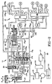
- One form of a hydraulic shift control embodying the concepts of the present invention and adapted selectively to engage and disengage conventional torque transmitting devices -- which may be in the nature of brakes and/or clutches -- appropriate for a drive or gear ratio to be sequentially engaged and/or disengaged is designated generally by the numeral 10 on the accompanying drawings.
- the present invention is particularly suited for use in combination with the transmission shift fork control mechanism identified generally by the numeral 11 ( Figure 1) herein.
- the shift fork control mechanism 11 includes means for providing a source of pressurised hydraulic fluid, such as a pump 12, that may be driven by an engine (not shown) through a conventional torque converter and power transmission assembly -- the combination torque converter and transmission assembly being identified generally by the numeral 13.
- a countershaft type transmission such as that shown in the aforesaid US Patent No. 5,009,116, may be driven by the torque converter in a conventional manner.
- the pump 12 delivers fluid from a reservoir 14 to a conventional regulator valve 15 which establishes the maximum pressure for the hydraulic fluid delivered by the main feed conduit 16. After the pressure requirement in the main feed conduit 16 is established, the excess fluid is directed to the torque converter and power transmission assembly 13, as well as to a conventional lubrication and cooling system 17, as is well known to the prior art.
- the main feed conduit 16 is in fluid communication with a manual range selector valve 18 and a branch feed conduit 16 A .
- the branch conduit 16 A feeds lateral subbranch feed conduits 16 A1 , 16 A2 , 16 A3 and 16 A4 .
- Lateral subbranch feed conduit 16 A2 is bifurcated to provide two conduits that communicate with shift fork controller 19.
- the manual range selector valve 18 selectively controls the shift fork controller 19 via either a forward flow control valve 20 or a reverse flow control valve 21.
- the lateral feed branch 16 A1 incorporates a normally closed on/off inhibit control solenoid valve 22 that selectively supplies hydraulic fluid against a control drive plug 23 in the reverse flow control valve 21.
- This provision for supplying hydraulic pressure selectively to translate the plug 23 in the reverse flow control valve 21 is intended to provide a means by which to effect a forward-to-reverse inhibiting function, and its operation will be hereinafter more fully described.
- the shift fork controller 19 When the manual range selector valve 18 is moved from neutral N to the forward drive range D pressurised fluid from the forward flow control valve 20 positions the shift fork controller 19 in the forward drive range, as depicted in Figure 1.
- the shift fork controller 19 may actuate a synchroniser (not shown), as by the control fork 24 that is translated by the shift fork controller 19. It should be appreciated that if a synchroniser is not employed, the control 10 can be utilised to provide the on-going and off-going pressures required to activate the torque transfer devices used with a planetary gear set.
- feed branch 16 A is bifurcated into two lateral subbranch feed conduits 16 A3 and 16 A4 which communicate, respectively, with the first and second, normally closed, on/off solenoid control valves 25 and 26.
- the first, normally closed, on/off solenoid control valve 25 communicates with a first two-position shuttle valve 28 via a feed passage 29.
- the first two-position shuttle valve 28 has a housing 30 with an axially oriented interior bore 31.
- a shuttle member 32 which is preferably provided with spacer stubs 33A and 33B that protrude axially outwardly from the opposite ends of the shuttle member 32, reciprocates within the plugged bore 31.
- the shuttle member 32 and particularly by virtue of the interaction of the axially protruding spacer stubs 33A and 33B with the housing 30 and its associated plug structure, defines first and second chambers 34 and 35, respectively, within the valve bore 31, as will be hereinafter more fully described.
- the feed passage 29 communicates with the first chamber 34 through an annular port 36.
- the first chamber 34 is continually accessible to any pressurised fluid received within the port 36 inasmuch as the spacer stub 33A engages the plug 39 in such a way as to assure that pressurised fluid introduced through port 36 will be immediately accessible to the chamber 34.
- a structural spacer stub is provided at each end of the shuttle member 32 in the first two-position shuttle valve 28 as well as at each end of the shuttle member 48 in the second two-position shuttle valve 40.
- the first chamber 34 in the first shuttle valve 28 selectively communicates with a control conduit 38 through annular port 39.
- the second chamber 35 in shuttle valve 28 communicates with the second two-position shuttle valve 40 through a cross feed passage 41 that opens though an annular port 42 in the second chamber 35 of the first shuttle valve 28.
- the second two-position shuttle valve 40 also has a housing 43 with an axially oriented interior bore 44.
- a shuttle member 45 reciprocates within the plugged bore 44.
- the shuttle member 45 defines first and second chambers 46 and 48 within the bore 44.
- the cross feed conduit 41 communicates with the first chamber 46 in the second shuttle valve 40 through an annular port 49.
- a signal conduit 50 similarly communicates with the first chamber 46 in the second shuttle valve 40, also through the annular port 49.
- a spring-assist conduit 52 communicates with the bore 44 in the second shuttle valve 40 through an annular port 53.
- the spring-assist conduit 52 will communicate with either the first or the second chamber 46 or 48 depending upon the position of the shuttle member 45 within the bore 44, as will become hereinafter more fully explained in conjunction with the operation of the control 10.
- a blocking signal conduit 54 also communicates with the second chamber 48 through an annular port 55.
- a first two-position spool valve is designated generally by the numeral 60.
- the spool valve 60 is comprised of a housing 61 which defines an axially oriented bore 62.
- a spool member 63 having a plurality of axially spaced radially extending lands 64, is disposed within the bore 62 for axial reciprocation.
- a first subchamber 65A is defined between axially spaced lands 64A and 64B; a second subchamber 65B is defined between axially spaced lands 64B and 64C; and a third subchamber 65C is defined between axially spaced lands 64C and 64D.
- a control chamber 66 is defined between the land 64D and the end face 68 of bore 62.
- the spool member 63 is biased within the bore 62 to the spring-set position depicted in Figures 4 and 5, principally by virtue of a spring member 69 that acts between the land 64A and a reaction/closure plate 70 retained within the open end of the bore 62 by an anchor pin 71.
- the reaction/closure plate 70 also serves to define a spring-assist chamber 72 between it and the land 64A.
- a locating stub shaft 73 extends axially outwardly from the reaction/closure plate 70 to be engaged by the protruding end 74 of the shaft portion 75 when the spool member 63 is in the pressure-set position, depicted in Figures 3 and 6 through 8.
- the engagement of the locating stub shaft 73 with the protruding end 74 defines the pressure-set position of the spool member 63. It should also be appreciated that the shaft portion 75 and the lands 64 comprise the spool valve member 63.
- the control conduit 38 communicates with the control chamber 66 through an annular port 76.
- the control chamber 66 also communicates with a pressure sensor 78 through a signal passage 79 -- when the spool valve member 63 is in the pressure-set position, depicted in Figures 3 and 6 through 8 -- that is fed through an annular port 80.
- the first/fifth drive ratio conduit 82 communicates with the bore 62 through an annular port 83.
- the specific subchamber 65 with which the various conduits and passages communicate will vary depending upon the position of the spool valve member 63, and for that reason, a discussion of the specific communication path through the spool valve 60 will be deferred until the operation of the control valving mechanism 10 is described. At this point, therefore, it shall only be noted that the first/fifth drive ratio conduit 82 also communicates with a second spool valve 85, as will be hereinafter more fully described.
- the spring-assist chamber 72 communicates with a signal conduit 86, and the signal conduit 86, in turn, communicates with a signal control subchamber 87 in the reverse flow control valve 21 ( Figures 1, 2 and 9).
- the signal conduit 86 also communicates with a pressure sensing switch 88.
- the pressure sensing switch 88 supplies a "reverse" operation signal for the shift fork control mechanism, and it serves the additional function of signalling a forward/reverse range inhibit state for the first spool valve 60 in the present control 10 as is more fully described in conjunction with Figure 10.
- a hydraulic return system 90 which directs hydraulic fluid back to the reservoir 14 ( Figure 1) -- communicates with the bore 62 at two axially spaced locations. Specifically, two drain or exhaust conduits 91 and 92 effect communication between the return system 90 and the bore 62 at annular ports 93 and 94, respectively.
- the first three-way modulating solenoid valve 100 also communicates with the bore 62 through a transfer conduit 101 that opens to an annular port 102 which circumscribes the axial bore 62.
- the first three-way modulating solenoid valve 100 also communicates with the return system 90 through an exhaust conduit 103.
- the first three-way modulating solenoid valve 100, as well as a second three-way modulating solenoid valve 105, are supplied with hydraulic fluid at substantially the line pressure provided to the manual range selector valve 18 by the main feed conduit 16. Specifically, line pressure is selectively fed through the manual range selector valve 18 to the forward or reverse flow control valves 20 or 21, respectively, and through one or the other of the flow control valves 20 or 21 to the feed passage 106.
- the solenoid feed passage 106 thereby provides hydraulic fluid at line pressure to the three-way modulating solenoid valves 100 and 105 through the respective branch feed passages 106 A and 106 B .
- the feed passage 106 connects directly with the forward and reverse flow valves 20 and 21, but the control valving mechanism 10 embodying the concepts of the present invention requires the incorporation of a shuttle valve which selectively connects one of the other of the flow control valves 20 and 21 to the feed passage 106.
- the high pressure selector shuttle valve 107 is provided at the intersection of the feed passage 106 with the branches 106 C and 106 D -- branch 106 C connecting the forward flow control valve 20 to the high pressure selector shuttle valve 107, and branch 106 D connecting the reverse flow control valve 21 to the high pressure selector shuttle valve 107.
- the third/reverse drive ratio conduit 108 communicates with the bore 62 through an annular port 109.
- the specific subchamber 65 with which the third/reverse drive ratio conduit 108 will communicate during the operation of the control valving mechanism 10 will be hereinafter fully described in conjunction with the explanation as to the operation of that mechanism.
- the second two-position spool valve 85 is also comprised of a housing 110 which defines a cylindrical bore 111.
- a spool member 112, having a plurality of axially spaced, radially extending lands 113 is disposed within the cylindrical bore 111 for axial reciprocation.
- a first subchamber 115A is defined between the lands 113A and 113B; a second subchamber 115B is defined between lands 113B and 113C; a third subchamber 113C is defined between lands 113C and 113D; a fourth subchamber 115D is defined between lands 113D and 113E; and, a fifth subchamber 115E is defined between lands 113E and 113F.
- a control chamber 116 is defined between the land 113F and the end face 118 of bore 111.
- the spool member 112 is biased within the bore 111 to the spring-set position, depicted in Figures 5-8, by the action of a spring member 119 that acts between land 113A and a reaction/closure plate 120 which is, in turn, retained within the open end of the cylindrical bore 111 by an anchor pin 121.
- the reaction/closure plate 120 also serves to define one wall of a spring-assist chamber 122 which extends between the land 113A and the reaction/closure plate 120.
- a locating stub shaft 123 extends axially outwardly from the reaction/closure plate 120 to be engaged by the protruding end 124 of the shaft portion 125 of the second spool valve member 112 when the spool valve member 112 is in the position depicted, for example, in Figure 3.
- engagement of the locating stub shaft 123 with the protruding end 124 defines the pressure-set position of the spool valve member 112.
- the spring-assist conduit 52 communicates with the spring-assist chamber 122 through an annular port 126.
- the hydraulic return system 90 communicates with the bore 111 at three axially spaced locations through exhaust conduits 130, 131 and 132 that open into the bore 111 through annular exhaust ports 133, 134 and 135, respectively.
- a sensor 146 communicates with the control chamber 116 in bore 111 by a signal conduit 148 that opens through an annular port 149.
- the blocking signal conduit 54 which opens to chamber 48 in the second two-position shuttle valve 40 through annular port 55, also communicates with the bore 111 in the second spool valve 85 through the annular port 144.
- the first/fifth drive ratio feed conduit 82 which communicates with the bore 62 in the first spool valve 60 through annular port 83, also communicates with the bore 111 in the second spool valve 85, as through the annular port 150.
- the second, normally closed, on/off solenoid control valve 26 communicates with the control chamber 116 in the second spool valve 85 via feed passage 151 that opens into the bore 111 through annular port 152.
- the second three-way modulating solenoid valve 105 communicates with the bore 111 in the second spool valve 85 through a transfer conduit 153 that opens into an annular port 154.
- the second three-way modulating solenoid valve 105 also communicates with the return system 90 through exhaust conduit 155.
- each of the on/off solenoid valves 22, 25 and 26 also communicate with the return system 90, as through the respective exhaust conduits 160, 161 and 162 when the referenced valve 22, 25 and/or 26 is in the "off" or hydraulically closed state.
- the three-way modulating solenoid valves 100 and 105 similarly communicate with the return system 90 through exhaust conduits 103 and 155, respectively.
- the transfer conduits 101 or 153 communicating with the closed three-way modulating solenoid valves 100 and/or 105, respectively will communicate through the closed modulating solenoid valve with the return system 90.
- the unique reverse flow valve 21 has a housing 165 which defines a cylindrical bore 166.
- a spool member 168 having a plurality of axially spaced radially extending lands 169, is disposed within the bore 166 for axial reciprocation.
- a first subchamber 170A is disposed between lands 169A and 169B, and a second subchamber 170B is disposed between lands 169B and 169C.
- the control plug 23 is disposed in axial alignment with the spool member 168, and the control plug 23 also reciprocates axially within the bore 166.
- the signal control subchamber 87 is located between the land 169C and the plug 23, and the signal conduit 86 communicates with the signal control subchamber 87.
- a control subchamber 171 is disposed between the plug 23 and the opposed end wall 172 of the housing 165, and the branch conduit 16 A1 communicates with the control subchamber 171.
- the spool member 168 is biased within bore 166 to a spring-set position by virtue of a compression spring 173 that is retained within the open end 174 of the bore 166, as by a transversely oriented retainer pin 175.
- the reverse flow control valve 21 is spring-set to the position depicted in Figure 1, such that when the manual range selector valve 18 is positioned in the reverse range R, pressurised hydraulic fluid flows from the main feed conduit 16 through the manual range selector valve 18 into the reverse supply conduit 176 to the reverse flow control valve 21 and through the flow control valve 21 into the reverse fork actuation passage 178.
- the reverse fork actuation passage 178 supplies pressurised hydraulic fluid into the reverse chamber 179 in the shift fork controller 19.
- pressurised hydraulic fluid is introduced into the signal conduit 86, which supplies the signal control subchamber 87.
- pressurised fluid within the signal control subchamber 87 serves to effect axial separation of the spool member 168 from the control drive plug 23 which permits the pressurised fluid in the reverse supply conduit 176 to pass through the reverse flow control valve 21 and into the feed passage branch 106 D , as depicted in Figure 2.
- the pressurised fluid in the feed passage branch 106 D will actuate the selector shuttle valve 107 to permit flow from the feed passage branch 106 D into feed passage 106, as represented in either Figure 2 or 9.
- the reverse flow control valve 21 initially directs pressurised hydraulic fluid from the manual range selector valve 18 to the shift fork controller 19 in order to establish the reverse drive range. After the reverse range is established, the pressurised fluid is directed to the feed passage 106 for supplying the modulating, solenoid valves 100 and 105.
- the solenoid inhibit valve 21 is, as will be hereinafter more fully apparent, activated in conjunction with selected drive ratios in the forward drive range.
- the reverse flow control valve 21 In the spring-set position of the reverse flow control valve 21 it will, as described in the previous paragraph, direct fluid flow from the manual selector valve 18 to the reverse chamber 179 in the shift fork controller 19, and in response to the resulting positioning of the shift fork controller 19 in the reverse position, pressurised fluid is returned to the signal control subchamber 87 in the reverse flow control valve 21 so that the flow control valve 21 will supply pressurised hydraulic fluid to the feed passage 106.
- the inhibit valve 21 will divert flow into the feed passage 106 rather than permit the shift fork controller 19 to be moved into the reverse drive position.
- the pressurised fluid will be flowing through the reverse flow control valve 21 rather than the forward flow control valve 20, the fluid will still be applied to the modulating solenoid valves 100 and 105.
- the logic circuit (not shown) will not alter the state of the forward drive ratio and pressurised hydraulic fluid to the torque transfer device will only be interrupted for the infinitesimally short time it takes for the operator to have moved the manual range selector valve 18 from the forward drive range D to the reverse drive range R. A return to the neutral N, park P or forward drive range position D of the manual range selector valve 18 will rectify the error.
- the middle land 180 of the manual range selector valve 18 blocks the flow of pressurised hydraulic fluid into or through the valve 18.
- motor vehicle transmissions generally include selectively engageable gear elements for providing multiple forward speed or drive ratios through which the output torque of the engine is applied to the drive wheels of the vehicle.
- gear elements which provide the various drive ratios are selectively activated, as through fluid operated torque transfer friction devices, such as clutches and brakes.
- shifting from one drive ratio to another generally involves releasing (disengaging) the torque transfer device(s) associated with the current drive ratio and applying (engaging) the torque transfer device(s) associated with the successive drive ratio.
- Any torque transfer device to be released during a particular shift sequence is conventionally referred to as the off-going torque transfer device, while the torque transfer device to be applied during that same shift sequence is referred to as the on-coming torque transfer device.
- the off-going torque transfer device is conventionally referred to as the off-going torque transfer device
- the on-coming torque transfer device is referred to as the on-coming torque transfer device.
- the shifting control effected by an automatic transmission is performed in conjunction with a logic control map and various inputs which reflect such system parameters as vehicle speed, engine throttle position and engine torque.
- Fluid pressure signals representative of the various system parameters are processed in an on-board computer and/or microprocessor to determine when a shift is in order and to actuate, in accordance with the logic control map, electronically controlled valves in the hydraulic control system which respond to the signals received from the computer to effect the required engagement and/or disengagement (and in the proper order) of the appropriate torque transfer devices necessary to secure the desired drive ratio changes to the output shaft of the transmission.
- the first drive or gear ratio is available after the manual range selector valve 18 has been shifted from the neutral N to the forward drive D range position, as depicted in Figure 1, which makes the pressurised hydraulic fluid available at the first and second modulating solenoid valves 100 and 105.
- the first drive range is established by actuating the on-going torque transfer friction device C1.
- the first drive ratio torque transfer device C1 is properly actuated when both the first and second on/off solenoid shift control valves 25 and 26, as well as the first three-way modulating solenoid valve 100, are in the hydraulically "on” state.
- the second three-way modulating solenoid valve 105 is in the hydraulically "off” state.
- the flow of hydraulic fluid at substantially line pressure is directed through the first, normally closed, on/off solenoid control valve 25 and into the first chamber 34 of the first two-position shuttle valve 28 via the feed passage 29.
- the shuttle member 32 is thereby translated into the position depicted in Figure 3, if it is not already in that position.
- the pressurised hydraulic fluid is permitted to pass through chamber 34 and the control conduit 38 into the control chamber 66 in the first two-position spool valve 60, as represented by the stippling of the pressurised portions.
- the spool member 63 is translated into the pressure-set position depicted in Figure 3.
- the flow of hydraulic fluid at substantially line pressure is directed through the second, normally closed, on/off solenoid shift control valve 26, along the feed passage 151 and into the control chamber 116 of the second two-position spool valve 85, as is also represented by stippling the pressurised portions.
- the spool member 112 is translated into the pressure-set position depicted in Figure 3.
- the pressure-set position of the spool member 63 in the first spool valve member 60 allows pressurised hydraulic fluid in control chamber 66 to activate pressure sensor 78, and the pressure-set position of the spool member 112 in the second spool valve 85 allows the pressurised hydraulic fluid within control chamber 116 to activate pressure sensor 146.
- Pressure sensor 88 remains deactivated. Pressure activation of both sensors 78 and 146 signals the customarily employed logic circuit in the on-board computer and/or microprocessor (not shown) that the control valving mechanism 10 is disposed appropriately for operation within the first, and also for shifting to, the second drive ratio, as will be hereinafter described.
- the hydraulic state of the on/off solenoid shift control valves 22, 25 and 26, the hydraulic state of the three-way modulating solenoid valves 100 and 105, as well as the hydraulic state of the pressure sensing switches 78, 88 and 146, are depicted in the logic table represented in Figure 11.
- the x designation on the logic table indicates that the solenoid and/or the solenoid valve so designated is hydraulically "on”. Similarly, the x designates that the pressure sensor is pressurised.
- pressurised hydraulic fluid is directed from the branch feed passage 106 A through the open first three-way modulating solenoid valve 100 along the transfer conduit 101 and into the subchamber 65B, through annular port 102, in the first spool valve 60.
- the pressurised hydraulic fluid is transmitted through the first/fifth drive ratio conduit 82 and into subchamber 115D in the second spool member 85 through the annular port 150.
- the pressurised hydraulic fluid passes outward, through annular port 142, and along feed conduit 138 to activate the torque transfer device C1 which effects operation of the first drive ratio.
- the particular disposition of the spool valves 60 and 85, with only the first three-way modulating solenoid valve 100 hydraulically open, permits hydraulic fluid only to activate the first drive ratio torque transfer device C1. Upshifting out of the first drive ratio may be accomplished by turning the first modulating solenoid valve 100 "off.” With the first solenoid valve turned off, the pressurised hydraulic fluid in torque transfer device C1 backflows along the first drive ratio conduit 138, through subchamber 115D in the second spool valve 85, along the first/fifth drive ratio conduit 81 and through subchamber 65B in the first two-position spool valve 60. From subchamber 65B, the pressurised hydraulic fluid passes through transfer conduit 101 into the first modulating solenoid valve 100 to exit into the return system 90 through exhaust conduit 103.
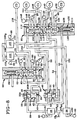
- the inhibit solenoid is turned “on", as depicted in Figure 2. Turning the inhibit solenoid 22 "on”, as was previously described, precludes a shift from the second drive ratio in the forward drive range directly into the reverse drive range.
- the second drive ratio is established with the control valving mechanism 10 disposed as depicted in Figure 3. That is, the on-going torque transfer device C2 is engaged, and the off-going torque transfer device C1 is substantially simultaneously disengaged, although, as previously noted, a slight overlap is generally deemed desirable, as is well known to the art.
- This sequencing from the first to the second drive ratio is controlled by opening the second three-way modulating solenoid valve 105 to engage the torque transfer friction device C2 and closing the first three-way modulating solenoid valve 100 to effect depressurisation of the torque transfer device C1.
- Closure of the three-way modulating solenoid valve 100 permits depressurisation of the torque transfer device C1 at a predetermined rate.
- valve 100 closes, the pressurised fluid within the torque transfer device C1 flows back through the chamber 115B in the second spool valve 85, along the first/fifth conduit 82 and through chamber 65B in the first spool valve 60 and into the first modulating solenoid valve 100 by transfer conduit 101.
- the exhaust conduit 103 communicates between the transfer conduit 101 and the return system 90 when the first modulating solenoid valve 100 is closed.
- Opening the second three-way modulating solenoid valve 105 permits the flow of pressurised hydraulic fluid to pass from the branch feed passage 106 B into the control mechanism 10. Specifically, fluid flow is directed from the second three-way modulating solenoid valve 105 via the transfer conduit 153 into subchamber 115B through annular port 154. The subchamber 115B is now in fluid communication with the torque transfer friction device C2 through the second drive ratio feed conduit 139, which communicates with subchamber 115B through annular port 143. The pressurised hydraulic fluid admitted to the control valving mechanism 10 through the second three-way modulating solenoid valve 105 thus activates the second drive ratio.
- the first solenoid valve 25 is turned “off” so that the passage of hydraulic fluid therethrough is precluded.
- the second solenoid valve 26 remains in the "on” state so that the passage of pressurised hydraulic fluid therethrough is maintained.
- first solenoid valve 25 "off” causes the hydraulic fluid in control chamber 66, particularly in response to the biasing action of spring 69, to backflow through control conduit 38 into and through the first chamber 34 in the first shuttle valve 28 and then through feed passage 29 into the first solenoid valve 25. From the solenoid valve 25, the fluid exits into the return system 90 through exhaust conduit 161. The first two-position spool valve 60 thus returns to the spring-set position ( Figure 4).
- control valving mechanism 10 Before the shift to the third drive ratio can be accomplished, the control valving mechanism 10 must be in the state represented by Figure 4.
- the inhibit solenoid valve 22 remains hydraulically "on” to preclude a direct shift from the third drive ratio in the forward drive range to the reverse range.
- the third drive ratio is established with the control valving mechanism 10 disposed in accordance with the representation in Figure 4. That is, the on-going torque transfer device C3 is engaged and, in appropriate coordination therewith, the off-going torque transfer device C2 is disengaged.
- This sequencing from the second to the third drive ratio is controlled by opening the first modulating solenoid valve 100 to engage torque transfer device C3 and closing the second modulating solenoid valve 105 to effect depressurisation of the torque transfer device C2 at a predetermined rate in order to effect the desired overlap.
- Opening the first modulating control valve 100 permits the flow of pressurised fluid to pass from the branch feed passage 106 A into the control valving mechanism 10. Specifically, the fluid flow is directed from the first modulating solenoid valve 100 via the transfer conduit 101 into subchamber 65B in the first spool valve 60. The subchamber 65B is now in fluid communication with the torque transfer device C3 through the third/reverse drive ratio conduit 108. The pressurised hydraulic fluid admitted to the control valving mechanism 10 through the first modulating solenoid valve 100 thus activates the third drive ratio.
- both the first and second spool valves 60 and 85 revert to the spring-set position, as depicted in Figure 5.
- the fourth drive ratio is established with the control valving mechanism 10 disposed in accordance with the representation in Figure 5. That is, the on-going torque transfer device C4 is engaged and, in appropriate coordination therewith, the off-going torque transfer device C3 is disengaged.
- This sequencing from the third to the fourth drive ratio is controlled by opening the second three-way modulating solenoid valve 105 so that pressurised hydraulic fluid can pass from the branch passage 106 B into the control valving mechanism 10. Specifically, fluid flow is directed from the second three-way modulating solenoid valve 105 via the transfer conduit 153 into subchamber 115B through annular port 154.
- the subchamber 115B is now in fluid communication with the torque transfer friction device C4 through the fourth drive ratio feed conduit 140, which communicates with subchamber 115B through annular port 144.
- the pressurised hydraulic fluid admitted to the control valving mechanism 10 through the three-way modulating solenoid valve 105 thus activates the fourth drive ratio.
- Closing the first three-way modulating solenoid valve 100 allows the pressurised hydraulic fluid in the torque transfer device C3 to backflow along the third/reverse drive ratio conduit 108 and through the subchamber 65B in the first spool valve 60 and along the transfer conduit 101 into the first modulating solenoid valve 100. From the first modulating solenoid valve 100, the fluid exits into the return system 90 through exhaust conduit 103.
- the present control 10 utilises a hydraulic interlock -- i.e.: pressurisation of the spring assist chamber 122, as is also depicted on Figure 6. Specifically, the pressurised hydraulic fluid received in subchamber 115B to actuate the torque transfer device C4 is also transferred, through blocking signal conduit 54, into chamber 48 in the second shuttle valve 40. The blocking signal conduit 54 opens into chamber 48 through port 55.
- chamber 48 causes the shuttle member 45 to move "upwardly", as viewed in Figure 6, such that the chamber 48 will communicate with one end of the spring-assist conduit 52, through port 53.
- the other end of the spring-assist conduit 52 communicates with the spring-assist chamber 122, as through port 126.
- Pressurisation of the spring-assist chamber 122 forces the spool member 112 to remain in the spring-set position, thereby precluding the passage of pressurised hydraulic fluid into the second drive ratio torque transfer device C2. This arrangement thereby precludes a fourth-to-second shift.
- the first on/off shift control solenoid 25 is turned “on", as depicted in Figure 6, so that pressurised hydraulic fluid can flow therethrough, and the second on/off shift control valve 26 is turned “off” so that the passage of hydraulic fluid therethrough is precluded.
- first on/off solenoid control valve 25 causes the pressurised hydraulic fluid to pass from the first control valve 25 along the feed passage 29 and into the chamber 34 in the first shuttle valve 28, thereby moving the shuttle member 32 to the "down" position, as depicted in Figure 6, so that the chamber 34 will communicate with control conduit 38 to pressurise control chamber 66 in the first spool valve 60. That is, fluid enters the spool valve 60 through annular port 76 and floods the control chamber 66, thereby translating the spool member 63 to the pressure-set position and triggering the pressure switch 78.
- the second spool valve 85 remains in the spring-set state so that the sensor 146 is not actuated; nor is sensor 88 activated. Activation of only sensor 78 signals the customarily employed logic circuit (not shown) that the control valving mechanism 10 is disposed appropriately for continued operation of the fourth drive ratio and subsequent actuation of the fifth drive ratio.
- the hydraulic state of the on/off solenoid control valves 22, 25 and 26, the hydraulic state of the three-way modulating solenoid valves 100 and 105, as well as the hydraulic state of the pressure sensing switches 78, 88 and 146, are depicted in the logic table represented in Figure 11.
- the fifth drive ratio is established with the control valving mechanism 10 disposed in accordance with the representation in Figures 6 and 7. That is, the on-going torque transfer device C5 is engaged and, in appropriate coordination therewith, the off-going torque transfer device C4 is disengaged.
- This sequencing from the fourth to the fifth drive ratio is controlled by opening the first modulating solenoid valve 100 to engage the torque transfer device C5 and closing the second modulating solenoid valve 105 to effect depressurisation of the torque transfer device C4 at a predetermined rate to effect the desired overlap.
- Closing the second modulating solenoid valve 105 permits depressurisation of the torque transfer device C4 at a predetermined rate to effect the desired overlap with respect to the opening of the first modulating solenoid valve 100.
- the pressurised hydraulic fluid in the off-going fourth drive ratio torque transfer device C4 backflows through the subchamber 115B which communicates with the second three-way modulating solenoid valve 105 through transfer conduit 153.
- the transfer conduit 153 will discharge the hydraulic fluid from torque transfer device C4 through the exhaust conduit 155 into the return system 90. This backflow is represented by the arrows in Figure 7.
- Opening the first modulating solenoid valve 100 introduces pressurised hydraulic fluid from the feed branch 106 A into the control valving mechanism 10. That is, the pressurised hydraulic fluid passes through the transfer conduit 101 and into subchamber 65B in the first spool valve 60 through annular port 102.
- the subchamber 65B is in fluid communication with subchamber 115D in the second spool valve 85 through the first/fifth drive ratio conduit 82.
- the subchamber 115D communicates with torque transfer friction device C5 through the fifth drive ratio feed conduit 141, which communicates with subchamber 115D through annular port 145.
- the line pressure described to actuate torque transfer device C5 by opening the first modulating solenoid valve 100 is depicted by the stippling in Figure 7.
- pressurised hydraulic fluid continues to flow from the first on/off solenoid shift control valve 25 into the control chamber 66 in order to maintain the pressure-set disposition of the spool member 63 in the first spool valve 60 and continue actuation of the pressure switch 78.
- pressurised hydraulic fluid also flows out of the subchamber 115D and into the signal conduit 50. From the signal conduit 50, the hydraulic fluid enters chamber 46 of the second shuttle valve 40, thereby translating the shuttle member 45 into the "down" position depicted in Figure 7.
- the pressurised fluid in chamber 46 is available to chamber 35 in the first shuttle valve 28, but the shuttle member 32 remains in the "down” position, inasmuch as chamber 34 was previously pressurised.
- the on/off solenoid control valves 25 and 26, along with the second three-way modulating solenoid valve 105 and the on/off inhibit solenoid valve 22, will be normally closed -- i.e.: hydraulically “off”, such that no flow is permitted between the line pressure side of the valve and the outlet of the valve when they are not electrically energised.
- the three-way modulating solenoid valve 100 is normally open -- i.e.: it is hydraulically "on” when not electrically energised, such that hydraulic fluid will flow from the line pressurise side of that valve to the outlet thereof even if no electrical energy is available.
- the use of a normally open configuration for the first three-way modulating solenoid valve 100 facilitates the provision of a desired operational failure mode for the control 10 when the system experiences a loss of electrical power.
- the use of a normally closed on/off solenoid inhibit valve 22 in the control 10 permits a shift from the third drive ratio into reverse, even with a loss of power.
- the present control 10 is designed to default to the third drive ratio during a loss of electrical energy when the transmission is operating in the first, second, third or fourth forward drive ratios.
- the present control 10 also defaults to the fifth drive ratio should the loss of electrical energy occur during operation in the fifth forward drive ratio.
- the return of the solenoid valve 26 to its "off" state allows the biasing pressure applied by the spring 119 in the second spool valve 85 to return that valve to its spring-set disposition. Even if that occurs before the second drive ratio torque transfer device C2 has exhausted all of the pressurised fluid therein, the spring-set position of the second spool valve 85 continues to maintain hydraulic communication between the torque transfer device C2 and the return system 90.
- the second drive ratio feed conduit 139 communicates with the return system 90 through the exhaust conduit 130 when the second spool valve 85 is in the spring-set state. Specifically, both the exhaust conduit 130 and the feed conduit 139 communicate with subchamber 115B.
- the loss of electrical energy to the on/off solenoid inhibitor valve 22 has the same effect, as described previously, with respect to a loss of electrical energy when operating in the first drive ratio.
- the control system 10 automatically reverts to the third drive ratio in response to an electrical failure while operating in the second drive ratio.
- Operation in the third drive ratio requires no electrical actuation of any solenoid. Accordingly, a loss of electrical energy while operating in the third drive ratio will effect no change in the operation of the transmission.
- the return of the first on/off solenoid valve 25 to its "off" state allows the biasing pressure applied by the spring 69 in the first spool valve 60 to return that valve to its spring-set disposition.
- the pressurised fluid within control chamber 66 in the first spool valve 60 will, under the biasing action of the spring 69, flow back along control conduit 38, through chamber 34 in the first shuttle valve 28, along feed passage 29 and into the return system 90 through exhaust conduit 161.
- the spring member 69 will place the first spool valve 60 in the spring-set state.
- the pressurised fluid supplied to chamber 46 in the second shuttle valve 40 is feedback, through cross feed conduit 41, into chamber 35 in the first shuttle valve 28 so that the shuttle member 35 in the first shuttle valve 28 will move from the down position depicted in Figure 7 to the up position depicted in Figure 8, thereby assuring a virtually uninterrupted supply of pressurised fluid to the control chamber 66 even through the first on/off solenoid valve 25 has been closed.
- the spool valve 60 is maintained in the pressure-set position despite the loss of electrical energy and the resulting closure of the first on/off solenoid valve 25.
- the first spool valve 60 remains disposed in the spring-set state, and because the first three-way modulating solenoid valve 100 is a normally open valve, operation of the transmission in the fifth drive ratio will be maintained even should a loss of electrical energy while the transmission is operating in the fifth drive ratio.
- the transmission will go to neutral when selected, removing fluid pressure from the clutches and interlocks.
- the third drive ratio will actuate.
- pressurised hydraulic fluid flows in signal conduit 86 to fill control subchamber 171 and thereby position the reverse flow control valve 21 in the pressure-set position depicted in Figure 9.
- the pressurised hydraulic fluid entering the reverse flow control valve 21 through the reverse supply conduit 196 flows into branch feed passage 106 D and through the high pressure selector shuttle valve 107 into feed passage 106.
- the pressurised hydraulic fluid is then presented at both the first and second three-way modulating solenoid valves 100 and 105 through branch passages 106 A and 106 B , respectively.
- torque transfer device C3 effects the reverse drive ratio when the manual range selector valve 18 is in the reverse drive position R. Operation of torque transfer device C3 is then effected by hydraulically closing the on/off solenoid valve 22 and opening solenoid valve 26 as well as the first three - way modulating solenoid valve 100.
- the first spool valve 60 is locked in the spring-set position, which is assured by having pressurised fluid introduced into the spring-assist chamber 72 through the appropriate conduits: i.e.: branch feed conduits 16 A1 and signal conduit 86.
- the second spool valve 85 is secured in the pressure-set position by the introduction of pressurised fluid into the control chamber 116 through the on/off solenoid valve 26.
- the signal processor will show pressure in both sensor 88 and 146, and the first three-way modulating solenoid valve 100 will be hydraulically opened to permit the pressurised fluid to flow through transfer conduit 101 and subchamber 65B into the third/reverse conduit 108 to apply the torque transfer device C3.
- the spool valve 60 will remain locked in the spring-set position by virtue of the spring member 69 itself, and also because the on/off solenoid 22 is normally closed.
- the first three-way modulating solenoid valve 100 is also normally open so that pressurised hydraulic fluid will continue to be available to the torque transfer device C3.
- the on/off solenoid valve 26 is normally closed so that the pressurised fluid in control chamber 116 will be drained back to the return system 90 through the exhaust conduit 162 that connects the on/off solenoid valve 26 to the return system 90.
- the absence of pressurised hydraulic fluid in control chamber 116 affects only the signal to the on-board computer and/or microprocessor, it will not affect operation within the reverse drive range.
- the pressure sensor switches 78, 88 and 146 serve to verify the disposition of the spool valves 60 and 86 as well as the forward and reverse flow control valves 20 and 21, respectively, prior to actuation of the modulating solenoid valves 100 or 105 in order to detect an incorrect range or direction change prior to the shift.
- Some prior known electronic transmission controls utilise a speed check subsequent to the shift to verify the operating range or ratio, and by that time it is too late to effect the necessary correction.
- an automatic transmission control embodying the concepts of the present invention is capable of providing a desirable delivery of actuating fluid to the torque transfer control devices, and accomplishes the other objects of the invention.
- each ratio requires the engagement of a different friction torque transfer device.
- the transition between successive forward ratios is accomplished by the disengagement of one of the friction torque transfer devices and the substantially simultaneous engagement of another friction torque transfer device. This is accomplished by a unique control system that employs two spool valves in combination with two modulating solenoid valves, as well as two on/off solenoid valves operating in conjunction with a pair of two-position shuttle valves.
- an improved transmission control valve mechanism embodying the concepts of the present invention is capable of effecting selective sequencing of a five speed, twin countershaft, automatic transmission by using only two modulating valves to control the on-coming and off-going hydraulic pressures that are applied to activate and deactivate the torque transfer devices by which sequencing of the transmission through the drive ratios is effected, but also that the other objects of the invention can be likewise accomplished.
Claims (9)
- Combinaison d'une commande de changement de vitesse hydraulique et d'un mécanisme de commande de changement de vitesse en marche avant / arrière destiné à une transmission automatique comprenant une pluralité de dispositifs de transfert de couple (C1 à C5), chaque dispositif de transfert de couple assurant un rapport de vitesse sélectionné ; la commande de changement de vitesse hydraulique comprenant une source (12) de pression hydraulique ; un premier moyen de vanne à deux positions à tiroir(60) ; une chambre de commande (66) incorporée dans le premier moyen de vanne à tiroir ; un premier moyen d'électrovanne de commande ouvert/fermé (25) relié à la source de pression hydraulique ; un premier moyen de conduit de commande (29, 38) destiné à diriger le fluide depuis le premier moyen d'électrovanne de commande ouvert/fermé vers la chambre de commande du premier moyen de vanne à tiroir pour obtenir un état déterminé par pression lorsque le premier moyen d'électrovanne de commande ouvert/fermé est enclenché ; un moyen de ressort (69) permettant de charger préliminairement le premier moyen de vanne à tiroir pour obtenir un état déterminé par ressort lorsque le premier moyen d'électrovanne de commande ouvert/fermé est fermé ; un deuxième moyen de vanne à deux positions à tiroir (85) ; une chambre de commande (116) incorporée dans le deuxième moyen de vanne à tiroir ; un deuxième moyen d'électrovanne de commande ouvert/fermé (26) relié à la source de pression hydraulique ; un deuxième moyen de conduit de commande (151) permettant de diriger le fluide provenant du deuxième moyen d'électrovanne de commande ouvert/fermé vers la chambre de commande du deuxième moyen de vanne à tiroir pour obtenir un état déterminé par pression du deuxième moyen de vanne à tiroir lorsque le deuxième moyen d'électrovanne de commande ouvert/fermé est ouvert ; un moyen de ressort (119) permettant de charger préliminairement le deuxième moyen de vanne à tiroir pour obtenir un état déterminé par ressort du deuxième moyen de vanne à tiroir lorsque le deuxième moyen d'électrovanne de commande ouvert/fermé est fermé ; un premier moyen d'électrovanne modulante (100) relié à la source de pression hydraulique et au premier moyen de vanne à tiroir permettant de diriger le fluide vers des dispositifs de transfert de couple sélectionnés ; et un deuxième moyen d'électrovanne modulante (105) relié à la source de pression hydraulique et au deuxième moyen de vanne à tiroir permettant de diriger le fluide vers des dispositifs de transfert de couple sélectionnés parmi les autres dispositifs de transfert de couple ; caractérisé en ce que le mécanisme de commande de changement de vitesse en marche avant / arrière comporte un moyen d'organe de commande actionné hydrauliquement de changement de vitesse en marche avant / arrière (19) relié à la source (12) de pression hydraulique ; un moyen de vanne de changement de vitesse à commande manuelle (18) relié à la source de pression hydraulique et permettant de sélectionner une pluralité de conditions de fonctionnement ; un premier moyen de vanne de régulation de débit (20) permettant de diriger le fluide provenant du moyen de vanne de régulation de débit vers le moyen d'organe de commande de changement de vitesse pour lui faire prendre une première position lorsque la vanne à commande manuelle est dans l'état de marche avant ; et un deuxième moyen de vanne de régulation de débit (21) permettant de diriger le fluide provenant du moyen de vanne de changement de vitesse à commande manuelle vers ledit moyen d'organe de commande de changement de vitesse pour lui faire prendre une deuxième position lorsque la vanne à commande manuelle est dans l'état de marche arrière ; en ce que le deuxième moyen de vanne de régulation de débit (21) comprend en outre un réceptacle (165) ; un élément de vanne à tiroir (168) logé dans le réceptacle et destiné à effectuer un mouvement de va et vient ; un élément coulissant (23) logé à l'intérieur du réceptacle et destiné à effectuer un déplacement axial ; un moyen de charge préliminaire (173) permettant de déplacer l'élément à tiroir vers une position déterminée par ressort ; le deuxième moyen de vanne de régulation de débit assurant la communication entre le moyen de vanne de changement de vitesse à commande manuelle (18) et le moyen d'organe de commande de changement de vitesse en marche avant / arrière (19) lorsque l'élément de vanne à tiroir du deuxième moyen de vanne de régulation de débit est dans la position déterminée par ressort ; et une sous-chambre de commande de signal (87) placée à l'intérieur du réceptacle et disposée sélectivement entre l'élément de vanne à tiroir et l'élément mobile pour déplacer l'élément de tiroir par rapport au dit élément mobile ; le deuxième moyen de vanne de régulation de débit assurant la communication entre le moyen de vanne de changement de vitesse à commande manuelle et les électrovannes de modulation (100, 105) lorsque le deuxième élément de vanne de régulation de débit est dans la position déterminée par pression.
- Combinaison selon la revendication 1, dans laquelle le premier moyen de vanne à tiroir (60) comprend en outre un moyen de système de retour hydraulique (90) ; et un premier élément de vanne à tiroir s'étendant axialement (63) et ayant une pluralité de faces (64A à 64D) qui sont espacées axialement le long de l'élément pour former les première, deuxième et troisième sous-chambres (65A à 65C).
- Combinaison selon la revendication 2, dans laquelle la première sous-chambre (65A) est en communication hydraulique sélective avec le moyen de système de retour hydraulique (90) et le deuxième élément de vanne à tiroir (85) ; dans laquelle la deuxième sous-chambre (65B) est en communication hydraulique sélective avec le premier moyen d'électrovanne modulante, avec le dispositif de transfert de couple (C3) qui assure un troisième rapport de vitesse, et avec le deuxième moyen de vanne à tiroir ; et dans laquelle la troisième sous-chambre (65C) est en communication hydraulique sélective avec le moyen de système de retour hydraulique et le dispositif de transfert de couple qui assure le troisième rapport de vitesse.
- Combinaison selon l'une quelconque des revendications 1 à 3, dans laquelle le deuxième moyen de vanne à tiroir (85) comprend en outre un deuxième élément de vanne à tiroir s'étendant axialement (112) et ayant une pluralité de faces (113A à 113F) qui sont espacées axialement le long de l'élément de vanne pour former les première, deuxième, troisième, quatrième et cinquième sous-chambres (115A à 115E).
- Combinaison selon la revendication 4, dans laquelle la cinquième sous-chambre (115E) du deuxième moyen de vanne à tiroir (85) communique de manière sélective avec le dispositif de transfert de couple (C5) qui assure un cinquième rapport de vitesse, et avec le moyen de système de retour hydraulique (90) ; dans laquelle la quatrième sous-chambre (115D) du deuxième moyen de vanne à tiroir communique de manière sélective avec le premier moyen de vanne à tiroir (60) et avec le dispositif de transfert de couple (C1) qui assure le premier rapport de vitesse ; avec le dispositif de transfert de couple qui assure le cinquième rapport de vitesse, et avec le moyen de système de retour hydraulique ; dans laquelle la troisième sous-chambre (115C) du deuxième moyen de vanne à tiroir communique de manière sélective avec le dispositif de transfert de couple qui assure le premier rapport de vitesse, avec le dispositif de transfert de couple (C4) qui assure un quatrième rapport de vitesse, et avec le moyen de système de retour hydraulique (90) ; dans laquelle la deuxième sous-chambre (115B) du deuxième moyen de vanne à tiroir communique de manière sélective avec le deuxième moyen d'électrovanne modulante (105), avec le dispositif de transfert de couple (C2) qui assure un deuxième rapport de vitesse et avec le dispositif de transfert de couple qui assure le quatrième rapport de vitesse; et dans laquelle la première sous-chambre (115A) du deuxième moyen de vanne à tiroir communique avec le moyen de système de retour hydraulique, et avec le dispositif de transfert de couple qui assure le deuxième rapport de vitesse.
- Combinaison selon la revendication 5, dans laquelle une activation sélective des premier et deuxième moyens d'électrovanne de commande ouvert/fermé (25, 28) et des premier et deuxième moyens d'électrovanne modulante (100, 105) permet de diriger exclusivement le fluide vers un dispositif de transfert de couple sélectionné.
- Combinaison selon l'une quelconque des revendications 1 à 6, dans laquelle le deuxième moyen de vanne de régulation de débit (21) comprend en outre une sous-chambre de commande (171) placée sélectivement à l'intérieur du réceptacle pour déplacer l'élément coulissant (23) et donc l'élément de vanne à tiroir (168) dans la position déterminée par pression.
- Combinaison selon la revendication 7, dans laquelle la sous-chambre de commande de signal (87) reçoit le fluide hydraulique sous pression provenant du moyen d'organe de commande de changement de vitesse (19) lorsque le moyen d'organe de commande de changement de vitesse est dans une position sélectionnée ; et dans laquelle un détecteur de pression (88) détermine l'état de pression de la sous-chambre de commande de signal.
- Combinaison selon la revendication 8, comprenant en outre de manière sélective une électrovanne d'inhibition ouvert/fermé (22) destinée à fournir un fluide hydraulique sous pression à la sous-chambre de commande (171).
Applications Claiming Priority (2)
| Application Number | Priority Date | Filing Date | Title |
|---|---|---|---|
| US08/199,400 US5445043A (en) | 1994-02-22 | 1994-02-22 | Hydraulic shift control for a power transmission |
| US199400 | 1994-02-22 |
Publications (2)
| Publication Number | Publication Date |
|---|---|
| EP0668455A1 EP0668455A1 (fr) | 1995-08-23 |
| EP0668455B1 true EP0668455B1 (fr) | 1998-09-02 |
Family
ID=22737340
Family Applications (1)
| Application Number | Title | Priority Date | Filing Date |
|---|---|---|---|
| EP95200126A Expired - Lifetime EP0668455B1 (fr) | 1994-02-22 | 1995-01-19 | Commande du changement de vitesse hydraulique pour une transmission |
Country Status (4)
| Country | Link |
|---|---|
| US (1) | US5445043A (fr) |
| EP (1) | EP0668455B1 (fr) |
| JP (1) | JP3615258B2 (fr) |
| DE (1) | DE69504378T2 (fr) |
Families Citing this family (26)
| Publication number | Priority date | Publication date | Assignee | Title |
|---|---|---|---|---|
| US5616093A (en) * | 1995-10-13 | 1997-04-01 | General Motors Corporation | Electro-hydraulic control system in a power transmission |
| US5601506A (en) * | 1995-10-13 | 1997-02-11 | General Motors Corporation | Electro-hydraulic control system in a power transmission |
| DE19546631A1 (de) * | 1995-12-14 | 1997-06-19 | Zahnradfabrik Friedrichshafen | Getriebesteuerung, insbesondere für ein elektrisch geschaltetes Automatikgetriebe in Vorgelegebauart |
| DE19601618A1 (de) * | 1996-01-18 | 1997-07-24 | Zahnradfabrik Friedrichshafen | Sicherheitssystem für ein Automatgetriebe |
| JP2840937B2 (ja) * | 1996-02-20 | 1998-12-24 | 本田技研工業株式会社 | 油圧作動式変速機の制御装置 |
| US5682791A (en) * | 1996-06-28 | 1997-11-04 | Caterpillar Inc. | Independent latching system for a transmission |
| JP4253899B2 (ja) * | 1999-02-24 | 2009-04-15 | アイシン・エィ・ダブリュ株式会社 | 自動変速機の油圧制御装置 |
| JP3461304B2 (ja) * | 1999-03-30 | 2003-10-27 | 本田技研工業株式会社 | 自動変速機の制御装置 |
| JP3523523B2 (ja) * | 1999-04-27 | 2004-04-26 | 本田技研工業株式会社 | 自動変速機の制御装置 |
| JP3507729B2 (ja) * | 1999-06-10 | 2004-03-15 | 本田技研工業株式会社 | 自動変速機の制御装置 |
| JP3461306B2 (ja) * | 1999-07-22 | 2003-10-27 | 本田技研工業株式会社 | 自動変速機の制御装置 |
| FR2801360B1 (fr) * | 1999-11-19 | 2002-04-05 | Renault | Procede et dispositif de pilotage d'une transmission automatique permettant de disposer d'un rapport supplementaire |
| DE10032680C1 (de) * | 2000-07-05 | 2001-10-25 | Daimler Chrysler Ag | Automatikgetriebe mit einer Steuervorrichtung zur Auswahl einer Getriebefahrstufe |
| EP1251300A3 (fr) * | 2001-04-16 | 2007-11-14 | Fuji Jukogyo Kabushiki Kaisha | Dispositif hydraulique de commande pour boite de vitesses manuelle automatisée |
| JP2002372144A (ja) * | 2001-06-15 | 2002-12-26 | Fuji Heavy Ind Ltd | 自動変速機の油圧制御装置 |
| US6898992B2 (en) * | 2003-08-08 | 2005-05-31 | Borgwarner, Inc. | Method for controlling the engagement force of the synchronizers of a dual clutch transmission |
| US8387476B2 (en) * | 2007-03-02 | 2013-03-05 | Borgwarner Inc. | Hydraulic actuation valve arrangement for dual clutch transmission |
| US8443956B2 (en) * | 2008-03-04 | 2013-05-21 | Borgwarner Inc. | Dual clutch transmission having area controlled clutch cooling circuit |
| CN101828055B (zh) * | 2008-04-18 | 2013-09-04 | 博格华纳公司 | 具有简化控制的双离合器变速器 |
| US8439804B2 (en) * | 2008-10-28 | 2013-05-14 | Allison Transmission, Inc. | Electro-hydraulic control including blocking features for multi-speed automatic transmission |
| US8376906B2 (en) * | 2008-12-09 | 2013-02-19 | Borgwarner Inc. | Automatic transmission for a hybrid vehicle |
| US8210976B2 (en) * | 2009-06-25 | 2012-07-03 | GM Global Technology Operations LLC | Control system for an automatic transmission having multiple default modes |
| CN102459965B (zh) | 2009-06-29 | 2014-11-05 | 博格华纳公司 | 用于在自动变速器控制模块中使用的液压阀 |
| WO2011082095A2 (fr) | 2009-12-31 | 2011-07-07 | Borgwarner Inc. | Transmission automatique ayant un circuit hydraulique de lubrification à basse pression et d'actionnement à pression élevée |
| WO2018118128A1 (fr) * | 2016-12-22 | 2018-06-28 | Eaton Corporation | Transmission à haut rendement et à efficacité élevée |
| IT202200003086A1 (it) * | 2022-02-18 | 2023-08-18 | Marelli Europe Spa | Circuito idraulico per una trasmissione meccanica servoassistita e metodo per controllare un circuito idraulico per una trasmissione meccanica servoassistita provvista di un cambio meccanico servoassistito |
Citations (3)
| Publication number | Priority date | Publication date | Assignee | Title |
|---|---|---|---|---|
| US4395927A (en) * | 1979-11-09 | 1983-08-02 | Robert Bosch Gmbh | Hydraulic regulating device for load shifted gears |
| EP0317936A2 (fr) * | 1987-11-25 | 1989-05-31 | BTR ENGINEERING (Australia) LIMITED | Commande électro-hydraulique pour une transmission automatique |
| US5240093A (en) * | 1991-05-30 | 1993-08-31 | Mercedes-Benz Ag | Configuration for the pressure supply to an automatic selector device of a change-speed gearbox |
Family Cites Families (4)
| Publication number | Priority date | Publication date | Assignee | Title |
|---|---|---|---|---|
| US4442727A (en) * | 1980-10-29 | 1984-04-17 | Alastair John Young | Control means for rotary power transmission |
| US5009116A (en) * | 1990-03-30 | 1991-04-23 | General Motors Corporation | Power transmission |
| JP2673613B2 (ja) * | 1991-07-31 | 1997-11-05 | 本田技研工業株式会社 | 車両用自動変速機の制御装置 |
| US5233878A (en) * | 1992-06-01 | 1993-08-10 | General Motors Corporation | Closed loop control for transmission shift fork position |
-
1994
- 1994-02-22 US US08/199,400 patent/US5445043A/en not_active Expired - Fee Related
-
1995
- 1995-01-19 EP EP95200126A patent/EP0668455B1/fr not_active Expired - Lifetime
- 1995-01-19 DE DE69504378T patent/DE69504378T2/de not_active Expired - Fee Related
- 1995-02-22 JP JP03387395A patent/JP3615258B2/ja not_active Expired - Fee Related
Patent Citations (3)
| Publication number | Priority date | Publication date | Assignee | Title |
|---|---|---|---|---|
| US4395927A (en) * | 1979-11-09 | 1983-08-02 | Robert Bosch Gmbh | Hydraulic regulating device for load shifted gears |
| EP0317936A2 (fr) * | 1987-11-25 | 1989-05-31 | BTR ENGINEERING (Australia) LIMITED | Commande électro-hydraulique pour une transmission automatique |
| US5240093A (en) * | 1991-05-30 | 1993-08-31 | Mercedes-Benz Ag | Configuration for the pressure supply to an automatic selector device of a change-speed gearbox |
Also Published As
| Publication number | Publication date |
|---|---|
| JP3615258B2 (ja) | 2005-02-02 |
| US5445043A (en) | 1995-08-29 |
| EP0668455A1 (fr) | 1995-08-23 |
| DE69504378T2 (de) | 1999-01-21 |
| JPH07259979A (ja) | 1995-10-13 |
| DE69504378D1 (de) | 1998-10-08 |
Similar Documents
| Publication | Publication Date | Title |
|---|---|---|
| EP0668455B1 (fr) | Commande du changement de vitesse hydraulique pour une transmission | |
| EP0768482B1 (fr) | Système de commande électro-hydraulique dans une transmission de puissance | |
| EP0768481B1 (fr) | Système de commande électro-hydraulique dans une transmission de puissance | |
| EP0628755B1 (fr) | Commande de transmission | |
| EP0691487B1 (fr) | Système de commande électronique et hydraulique pour transmission automatique à quatre vitesses d'un véhicule automobile | |
| US4841816A (en) | Hydraulic control for a power transmission with a manual range selector valve | |
| US5643125A (en) | Electro-hydraulic control system in a power transmission | |
| US6077182A (en) | Relay valve with latch area for controlling a friction device | |
| EP0783640B1 (fr) | Systeme de transmission automatique pour vehicule automoteur | |
| US5540634A (en) | Hydraulic control system of four-speed automatic transmission for automotive vehicle | |
| US5509868A (en) | Governor interlock valve | |
| US5425688A (en) | Hydraulic forward/reverse shift fork control for a power transmission | |
| US5492027A (en) | Rotary shift control valving mechanism for a power transmission | |
| US5669853A (en) | Hydraulic control system for four-speed automatic transmission of automotive vehicle | |
| KR100288213B1 (ko) | 차량용 자동변속기의 유압 제어 시스템 | |
| US5637056A (en) | Automatic transmission system for automotive vehicle | |
| US7048104B2 (en) | Selective bypass of solenoid-controlled supply to friction elements of an automatic transmission | |
| EP0622571B1 (fr) | Système de commande hydraulique pour une transmission | |
| KR0180423B1 (ko) | 차량용 자동변속기의 유압 제어시스템 | |
| KR0142455B1 (ko) | 자동차용 4속 자동 변속기의 유압 제어시스템 | |
| KR19990059844A (ko) | 자동변속기용 유압 제어 시스템 | |
| KR100293660B1 (ko) | 무단변속기의전,후진제어시스템 | |
| KR100222829B1 (ko) | 자동변속기의 유압 제어 시스템 및 그 제어방법 | |
| KR100216057B1 (ko) | 자동변속기의 유압 제어 시스템 제어방법 | |
| KR19990070217A (ko) | 자동변속기용 유압 제어 시스템 |
Legal Events
| Date | Code | Title | Description |
|---|---|---|---|
| PUAI | Public reference made under article 153(3) epc to a published international application that has entered the european phase |
Free format text: ORIGINAL CODE: 0009012 |
|
| AK | Designated contracting states |
Kind code of ref document: A1 Designated state(s): DE FR GB IT |
|
| 17P | Request for examination filed |
Effective date: 19960223 |
|
| 17Q | First examination report despatched |
Effective date: 19970422 |
|
| GRAG | Despatch of communication of intention to grant |
Free format text: ORIGINAL CODE: EPIDOS AGRA |
|
| GRAG | Despatch of communication of intention to grant |
Free format text: ORIGINAL CODE: EPIDOS AGRA |
|
| GRAH | Despatch of communication of intention to grant a patent |
Free format text: ORIGINAL CODE: EPIDOS IGRA |
|
| GRAH | Despatch of communication of intention to grant a patent |
Free format text: ORIGINAL CODE: EPIDOS IGRA |
|
| GRAA | (expected) grant |
Free format text: ORIGINAL CODE: 0009210 |
|
| ITF | It: translation for a ep patent filed |
Owner name: BARZANO' E ZANARDO ROMA S.P.A. |
|
| AK | Designated contracting states |
Kind code of ref document: B1 Designated state(s): DE FR GB IT |
|
| REF | Corresponds to: |
Ref document number: 69504378 Country of ref document: DE Date of ref document: 19981008 |
|
| ET | Fr: translation filed | ||
| PLBE | No opposition filed within time limit |
Free format text: ORIGINAL CODE: 0009261 |
|
| STAA | Information on the status of an ep patent application or granted ep patent |
Free format text: STATUS: NO OPPOSITION FILED WITHIN TIME LIMIT |
|
| 26N | No opposition filed | ||
| REG | Reference to a national code |
Ref country code: GB Ref legal event code: IF02 |
|
| PG25 | Lapsed in a contracting state [announced via postgrant information from national office to epo] |
Ref country code: IT Free format text: LAPSE BECAUSE OF NON-PAYMENT OF DUE FEES Effective date: 20050119 |
|
| PGFP | Annual fee paid to national office [announced via postgrant information from national office to epo] |
Ref country code: GB Payment date: 20060113 Year of fee payment: 12 |
|
| PGFP | Annual fee paid to national office [announced via postgrant information from national office to epo] |
Ref country code: FR Payment date: 20060117 Year of fee payment: 12 |
|
| PGFP | Annual fee paid to national office [announced via postgrant information from national office to epo] |
Ref country code: DE Payment date: 20060228 Year of fee payment: 12 |
|
| PG25 | Lapsed in a contracting state [announced via postgrant information from national office to epo] |
Ref country code: DE Free format text: LAPSE BECAUSE OF NON-PAYMENT OF DUE FEES Effective date: 20070801 |
|
| GBPC | Gb: european patent ceased through non-payment of renewal fee |
Effective date: 20070119 |
|
| REG | Reference to a national code |
Ref country code: FR Ref legal event code: ST Effective date: 20070930 |
|
| PG25 | Lapsed in a contracting state [announced via postgrant information from national office to epo] |
Ref country code: GB Free format text: LAPSE BECAUSE OF NON-PAYMENT OF DUE FEES Effective date: 20070119 |
|
| PG25 | Lapsed in a contracting state [announced via postgrant information from national office to epo] |
Ref country code: FR Free format text: LAPSE BECAUSE OF NON-PAYMENT OF DUE FEES Effective date: 20070131 |