EP0668455B1 - Hydraulische Schaltsteuerung für ein Getriebe - Google Patents
Hydraulische Schaltsteuerung für ein Getriebe Download PDFInfo
- Publication number
- EP0668455B1 EP0668455B1 EP95200126A EP95200126A EP0668455B1 EP 0668455 B1 EP0668455 B1 EP 0668455B1 EP 95200126 A EP95200126 A EP 95200126A EP 95200126 A EP95200126 A EP 95200126A EP 0668455 B1 EP0668455 B1 EP 0668455B1
- Authority
- EP
- European Patent Office
- Prior art keywords
- valve means
- control
- valve
- spool valve
- torque transfer
- Prior art date
- Legal status (The legal status is an assumption and is not a legal conclusion. Google has not performed a legal analysis and makes no representation as to the accuracy of the status listed.)
- Expired - Lifetime
Links
Images


Classifications
-
- F—MECHANICAL ENGINEERING; LIGHTING; HEATING; WEAPONS; BLASTING
- F16—ENGINEERING ELEMENTS AND UNITS; GENERAL MEASURES FOR PRODUCING AND MAINTAINING EFFECTIVE FUNCTIONING OF MACHINES OR INSTALLATIONS; THERMAL INSULATION IN GENERAL
- F16H—GEARING
- F16H61/00—Control functions within control units of change-speed- or reversing-gearings for conveying rotary motion ; Control of exclusively fluid gearing, friction gearing, gearings with endless flexible members or other particular types of gearing
- F16H61/12—Detecting malfunction or potential malfunction, e.g. fail safe; Circumventing or fixing failures
-
- F—MECHANICAL ENGINEERING; LIGHTING; HEATING; WEAPONS; BLASTING
- F16—ENGINEERING ELEMENTS AND UNITS; GENERAL MEASURES FOR PRODUCING AND MAINTAINING EFFECTIVE FUNCTIONING OF MACHINES OR INSTALLATIONS; THERMAL INSULATION IN GENERAL
- F16H—GEARING
- F16H61/00—Control functions within control units of change-speed- or reversing-gearings for conveying rotary motion ; Control of exclusively fluid gearing, friction gearing, gearings with endless flexible members or other particular types of gearing
- F16H61/02—Control functions within control units of change-speed- or reversing-gearings for conveying rotary motion ; Control of exclusively fluid gearing, friction gearing, gearings with endless flexible members or other particular types of gearing characterised by the signals used
- F16H61/0202—Control functions within control units of change-speed- or reversing-gearings for conveying rotary motion ; Control of exclusively fluid gearing, friction gearing, gearings with endless flexible members or other particular types of gearing characterised by the signals used the signals being electric
- F16H61/0204—Control functions within control units of change-speed- or reversing-gearings for conveying rotary motion ; Control of exclusively fluid gearing, friction gearing, gearings with endless flexible members or other particular types of gearing characterised by the signals used the signals being electric for gearshift control, e.g. control functions for performing shifting or generation of shift signal
- F16H61/0206—Layout of electro-hydraulic control circuits, e.g. arrangement of valves
-
- F—MECHANICAL ENGINEERING; LIGHTING; HEATING; WEAPONS; BLASTING
- F16—ENGINEERING ELEMENTS AND UNITS; GENERAL MEASURES FOR PRODUCING AND MAINTAINING EFFECTIVE FUNCTIONING OF MACHINES OR INSTALLATIONS; THERMAL INSULATION IN GENERAL
- F16H—GEARING
- F16H59/00—Control inputs to control units of change-speed-, or reversing-gearings for conveying rotary motion
- F16H59/68—Inputs being a function of gearing status
- F16H2059/6807—Status of gear-change operation, e.g. clutch fully engaged
-
- F—MECHANICAL ENGINEERING; LIGHTING; HEATING; WEAPONS; BLASTING
- F16—ENGINEERING ELEMENTS AND UNITS; GENERAL MEASURES FOR PRODUCING AND MAINTAINING EFFECTIVE FUNCTIONING OF MACHINES OR INSTALLATIONS; THERMAL INSULATION IN GENERAL
- F16H—GEARING
- F16H59/00—Control inputs to control units of change-speed-, or reversing-gearings for conveying rotary motion
- F16H59/68—Inputs being a function of gearing status
- F16H2059/683—Sensing pressure in control systems or in fluid controlled devices, e.g. by pressure sensors
-
- F—MECHANICAL ENGINEERING; LIGHTING; HEATING; WEAPONS; BLASTING
- F16—ENGINEERING ELEMENTS AND UNITS; GENERAL MEASURES FOR PRODUCING AND MAINTAINING EFFECTIVE FUNCTIONING OF MACHINES OR INSTALLATIONS; THERMAL INSULATION IN GENERAL
- F16H—GEARING
- F16H61/00—Control functions within control units of change-speed- or reversing-gearings for conveying rotary motion ; Control of exclusively fluid gearing, friction gearing, gearings with endless flexible members or other particular types of gearing
- F16H61/02—Control functions within control units of change-speed- or reversing-gearings for conveying rotary motion ; Control of exclusively fluid gearing, friction gearing, gearings with endless flexible members or other particular types of gearing characterised by the signals used
- F16H61/0202—Control functions within control units of change-speed- or reversing-gearings for conveying rotary motion ; Control of exclusively fluid gearing, friction gearing, gearings with endless flexible members or other particular types of gearing characterised by the signals used the signals being electric
- F16H61/0251—Elements specially adapted for electric control units, e.g. valves for converting electrical signals to fluid signals
- F16H2061/0258—Proportional solenoid valve
-
- F—MECHANICAL ENGINEERING; LIGHTING; HEATING; WEAPONS; BLASTING
- F16—ENGINEERING ELEMENTS AND UNITS; GENERAL MEASURES FOR PRODUCING AND MAINTAINING EFFECTIVE FUNCTIONING OF MACHINES OR INSTALLATIONS; THERMAL INSULATION IN GENERAL
- F16H—GEARING
- F16H61/00—Control functions within control units of change-speed- or reversing-gearings for conveying rotary motion ; Control of exclusively fluid gearing, friction gearing, gearings with endless flexible members or other particular types of gearing
- F16H61/02—Control functions within control units of change-speed- or reversing-gearings for conveying rotary motion ; Control of exclusively fluid gearing, friction gearing, gearings with endless flexible members or other particular types of gearing characterised by the signals used
- F16H61/0202—Control functions within control units of change-speed- or reversing-gearings for conveying rotary motion ; Control of exclusively fluid gearing, friction gearing, gearings with endless flexible members or other particular types of gearing characterised by the signals used the signals being electric
- F16H61/0251—Elements specially adapted for electric control units, e.g. valves for converting electrical signals to fluid signals
- F16H2061/026—On-off solenoid valve
-
- F—MECHANICAL ENGINEERING; LIGHTING; HEATING; WEAPONS; BLASTING
- F16—ENGINEERING ELEMENTS AND UNITS; GENERAL MEASURES FOR PRODUCING AND MAINTAINING EFFECTIVE FUNCTIONING OF MACHINES OR INSTALLATIONS; THERMAL INSULATION IN GENERAL
- F16H—GEARING
- F16H61/00—Control functions within control units of change-speed- or reversing-gearings for conveying rotary motion ; Control of exclusively fluid gearing, friction gearing, gearings with endless flexible members or other particular types of gearing
- F16H61/12—Detecting malfunction or potential malfunction, e.g. fail safe; Circumventing or fixing failures
- F16H2061/1232—Bringing the control into a predefined state, e.g. giving priority to particular actuators or gear ratios
-
- F—MECHANICAL ENGINEERING; LIGHTING; HEATING; WEAPONS; BLASTING
- F16—ENGINEERING ELEMENTS AND UNITS; GENERAL MEASURES FOR PRODUCING AND MAINTAINING EFFECTIVE FUNCTIONING OF MACHINES OR INSTALLATIONS; THERMAL INSULATION IN GENERAL
- F16H—GEARING
- F16H61/00—Control functions within control units of change-speed- or reversing-gearings for conveying rotary motion ; Control of exclusively fluid gearing, friction gearing, gearings with endless flexible members or other particular types of gearing
- F16H61/12—Detecting malfunction or potential malfunction, e.g. fail safe; Circumventing or fixing failures
- F16H2061/1244—Keeping the current state
-
- F—MECHANICAL ENGINEERING; LIGHTING; HEATING; WEAPONS; BLASTING
- F16—ENGINEERING ELEMENTS AND UNITS; GENERAL MEASURES FOR PRODUCING AND MAINTAINING EFFECTIVE FUNCTIONING OF MACHINES OR INSTALLATIONS; THERMAL INSULATION IN GENERAL
- F16H—GEARING
- F16H61/00—Control functions within control units of change-speed- or reversing-gearings for conveying rotary motion ; Control of exclusively fluid gearing, friction gearing, gearings with endless flexible members or other particular types of gearing
- F16H61/12—Detecting malfunction or potential malfunction, e.g. fail safe; Circumventing or fixing failures
- F16H2061/1256—Detecting malfunction or potential malfunction, e.g. fail safe; Circumventing or fixing failures characterised by the parts or units where malfunctioning was assumed or detected
- F16H2061/1292—Detecting malfunction or potential malfunction, e.g. fail safe; Circumventing or fixing failures characterised by the parts or units where malfunctioning was assumed or detected the failing part is the power supply, e.g. the electric power supply
-
- F—MECHANICAL ENGINEERING; LIGHTING; HEATING; WEAPONS; BLASTING
- F16—ENGINEERING ELEMENTS AND UNITS; GENERAL MEASURES FOR PRODUCING AND MAINTAINING EFFECTIVE FUNCTIONING OF MACHINES OR INSTALLATIONS; THERMAL INSULATION IN GENERAL
- F16H—GEARING
- F16H2306/00—Shifting
-
- F—MECHANICAL ENGINEERING; LIGHTING; HEATING; WEAPONS; BLASTING
- F16—ENGINEERING ELEMENTS AND UNITS; GENERAL MEASURES FOR PRODUCING AND MAINTAINING EFFECTIVE FUNCTIONING OF MACHINES OR INSTALLATIONS; THERMAL INSULATION IN GENERAL
- F16H—GEARING
- F16H61/00—Control functions within control units of change-speed- or reversing-gearings for conveying rotary motion ; Control of exclusively fluid gearing, friction gearing, gearings with endless flexible members or other particular types of gearing
- F16H61/02—Control functions within control units of change-speed- or reversing-gearings for conveying rotary motion ; Control of exclusively fluid gearing, friction gearing, gearings with endless flexible members or other particular types of gearing characterised by the signals used
- F16H61/0202—Control functions within control units of change-speed- or reversing-gearings for conveying rotary motion ; Control of exclusively fluid gearing, friction gearing, gearings with endless flexible members or other particular types of gearing characterised by the signals used the signals being electric
- F16H61/0204—Control functions within control units of change-speed- or reversing-gearings for conveying rotary motion ; Control of exclusively fluid gearing, friction gearing, gearings with endless flexible members or other particular types of gearing characterised by the signals used the signals being electric for gearshift control, e.g. control functions for performing shifting or generation of shift signal
- F16H61/0246—Control functions within control units of change-speed- or reversing-gearings for conveying rotary motion ; Control of exclusively fluid gearing, friction gearing, gearings with endless flexible members or other particular types of gearing characterised by the signals used the signals being electric for gearshift control, e.g. control functions for performing shifting or generation of shift signal characterised by initiating reverse gearshift
-
- F—MECHANICAL ENGINEERING; LIGHTING; HEATING; WEAPONS; BLASTING
- F16—ENGINEERING ELEMENTS AND UNITS; GENERAL MEASURES FOR PRODUCING AND MAINTAINING EFFECTIVE FUNCTIONING OF MACHINES OR INSTALLATIONS; THERMAL INSULATION IN GENERAL
- F16H—GEARING
- F16H61/00—Control functions within control units of change-speed- or reversing-gearings for conveying rotary motion ; Control of exclusively fluid gearing, friction gearing, gearings with endless flexible members or other particular types of gearing
- F16H61/16—Inhibiting or initiating shift during unfavourable conditions, e.g. preventing forward reverse shift at high vehicle speed, preventing engine over speed
-
- F—MECHANICAL ENGINEERING; LIGHTING; HEATING; WEAPONS; BLASTING
- F16—ENGINEERING ELEMENTS AND UNITS; GENERAL MEASURES FOR PRODUCING AND MAINTAINING EFFECTIVE FUNCTIONING OF MACHINES OR INSTALLATIONS; THERMAL INSULATION IN GENERAL
- F16H—GEARING
- F16H61/00—Control functions within control units of change-speed- or reversing-gearings for conveying rotary motion ; Control of exclusively fluid gearing, friction gearing, gearings with endless flexible members or other particular types of gearing
- F16H61/68—Control functions within control units of change-speed- or reversing-gearings for conveying rotary motion ; Control of exclusively fluid gearing, friction gearing, gearings with endless flexible members or other particular types of gearing specially adapted for stepped gearings
- F16H61/684—Control functions within control units of change-speed- or reversing-gearings for conveying rotary motion ; Control of exclusively fluid gearing, friction gearing, gearings with endless flexible members or other particular types of gearing specially adapted for stepped gearings without interruption of drive
- F16H61/688—Control functions within control units of change-speed- or reversing-gearings for conveying rotary motion ; Control of exclusively fluid gearing, friction gearing, gearings with endless flexible members or other particular types of gearing specially adapted for stepped gearings without interruption of drive with two inputs, e.g. selection of one of two torque-flow paths by clutches
-
- Y—GENERAL TAGGING OF NEW TECHNOLOGICAL DEVELOPMENTS; GENERAL TAGGING OF CROSS-SECTIONAL TECHNOLOGIES SPANNING OVER SEVERAL SECTIONS OF THE IPC; TECHNICAL SUBJECTS COVERED BY FORMER USPC CROSS-REFERENCE ART COLLECTIONS [XRACs] AND DIGESTS
- Y10—TECHNICAL SUBJECTS COVERED BY FORMER USPC
- Y10T—TECHNICAL SUBJECTS COVERED BY FORMER US CLASSIFICATION
- Y10T74/00—Machine element or mechanism
- Y10T74/19—Gearing
- Y10T74/19219—Interchangeably locked
- Y10T74/19251—Control mechanism
Landscapes
- Engineering & Computer Science (AREA)
- General Engineering & Computer Science (AREA)
- Mechanical Engineering (AREA)
- Control Of Transmission Device (AREA)
- Gear-Shifting Mechanisms (AREA)
Claims (9)
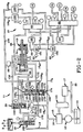
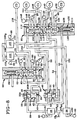
- Kombination aus einer hydraulischen Schaltsteuerung und einem Vorwärts/ Rückwärts-Schaltsteuermechanismus für ein Automatikgetriebe, das mehrere Drehmomentübertragungsvorrichtungen (C1 - C5) umfaßt, wobei jede Drehmomentübertragungsvorrichtung ein ausgewähltes Antriebsverhältnis bewirkt; wobei die hydraulische Schaltsteuerung umfaßt: eine Fluiddruckquelle (12); ein erstes Zwei-Positionen-Trommelventilmittel (60); eine Steuerkammer (66), die in das erste Trommelventilmittel eingearbeitet ist; ein erstes Ein/Aus-Solenoidsteuerventilmittel (25), das mit der Fluiddruckquelle verbunden ist; ein erstes Steuerleitungsmittel (29, 38), um Fluid von dem ersten Ein/Aus-Solenoidsteuermittel zur Steuerkammer in dem ersten Trommelventilmittel zu leiten und somit einen Druckeinstellungszustand zu bewirken, wenn das erste Ein/Aus-Solenoidsteuerventilmittel eingeschaltet ist, ein Federmittel (69), um das erste Trommelventilmittel vorzuspannen und somit einen Federeinstellungszustand zu bewirken, wenn das erste Ein/Aus-Solenoidsteuerventilmittel ausgeschaltet ist; ein zweites Zwei-Positionen-Trommelventilmittel (85); eine Steuerkammer (116), die in das zweite Trommelventilmittel eingearbeitet ist; ein zweites Ein/Aus-Solenoidsteuerventilmittel (26), das mit der Fluiddruckquelle verbunden ist; ein zweites Steuerleitungsmittel (151), um Fluid von dem zweiten Ein/Aus-Solenoidsteuerventilmittel zur Steuerkammer in dem zweiten Trommelventilmittel zu leiten und somit einen Druckeinstellungszustand für das zweite Trommelventilmittel zu bewirken, wenn das zweite Ein/Aus-Solenoidsteuermittel eingeschaltet ist; ein Federmittel (119), um das zweite Trommelventilmittel vorzuspannen und somit einen Federeinstellungszustand für das zweite Trommelventilmittel zu bewirken, wenn das zweite Ein/Aus-Solenoidsteuerventilmittel ausgeschaltet ist; ein erstes Modulationssolenoidventilmittel (100), das mit der Fluiddruckquelle und mit dem ersten Trommelventilmittel verbunden ist, um die Fluidströmung zu ausgewählten Drehmomentübertragungsvorrichtungen zu leiten; und ein zweites Modulationssolenoidventilmittel (105), das mit der Fluiddruckquelle und mit dem zweiten Trommelventilmittel verbunden ist, um die Fluidströmung zu ausgewählten Drehmomentübertragungsvorrichtungen der anderen Drehmomentübertragungsvorrichtungen zu leiten;
dadurch gekennzeichnet,
daß der Vorwärts/Rückwärts-Schaltsteuermechanismus aufweist:ein fluidbetätigtes Vorwärts/Rückwärts-Schaltcontrollermittel (19), das mit der Fluiddruckquelle (12) verbunden ist; ein Handschaltventilmittel (18), das mit der Fluiddruckquelle verbunden ist, um mehrere Betriebszustände auszuwählen; ein erstes Durchflußregelventilmittel (20), um Fluid von dem Handschaltventilmittel zum Schaltcontrollermittel zu leiten und somit eine erste Position in diesem zu bewirken, wenn sich das Handventil im Vorwärtsfahrzustand befindet; und ein zweites Durchflußregelventilmittel (21), um Fluid von dem Handschaltventilmittel zum Schaltcontrollermittel zu leiten und somit eine zweite Position in diesem zu bewirken, wenn sich das Handventil im Rückwärtsfahrzustand befindet; wobei das zweite Durchflußregelventilmittel (21) ferner umfaßt: ein Gehäuse (165);ein Trommelventilelement (168), das in dem Gehäuse aufgenommen ist, so daß es sich axial hin- und herbewegen kann; ein Stopfenelement (23), das in dem Gehäuse aufgenommen ist, so daß es sich axial verschieben kann; ein Vorspannungsmittel (173), um das Trommelelement in eine Federeinstellungsposition zu bewegen; wobei das zweite Durchflußregelventilmittel eine Verbindung zwischen dem Handschaltventilmittel (18) und dem Vorwärts/Rückwärts-Schaltcontrollermittel (19) bewirkt, wenn sich das Trommelventilelement in dem zweiten Durchflußregelventilmittel in der Federeinstellungsposition befindet; und eine Signalsteuerungsunterkammer (87), die sich in dem Gehäuse befindet und zwischen dem Trommelventilelement und dem Stopfenelement angeordnet ist, um das Trommelelement selektiv in bezug auf das Stopfenelement zu verschieben; wobei das zweite Durchflußregelventilmittel eine Verbindung zwischen dem Handschaltventilmittel und den Modulationssolenoidventilen (100, 105) bewirkt, wenn sich das zweite Durchflußregelventilelement in der Druckeinstellungsposition befindet. - Kombination nach Anspruch 1,
wobei das erste Trommelventilmittel (60) ferner ein hydraulisches Rückführsystemmittel (90) und ein erstes, sich axial erstreckendes Trommelventilelement (63) umfaßt, das mehrere Stege (64A - D) aufweist, die axial entlang von diesem beabstandet sind, um eine erste, eine zweite und eine dritte Unterkammer (65A - C) festzulegen. - Kombination nach Anspruch 2,
wobei die erste Unterkammer (65A) in selektiver Fluidverbindung mit dem hydraulischen Rückführsystemmittel (90) und dem zweiten Trommelventilelement (85) steht; wobei die zweite Unterkammer (65B) in selektiver Fluidverbindung mit dem ersten Modulationssolenoidventilmittel, der Drehmomentübertragungsvorrichtung (C3), die ein drittes Antriebsverhältnis bewirkt, und dem zweiten Trommelventilmittel steht; und wobei die dritte Unterkammer (65C) in selektiver Fluidverbindung mit dem hydraulischen Rückführsystemmittel und der Drehmomentübertragungsvorrichtung steht, die das dritte Antriebsverhältnis bewirkt. - Kombination nach einem der Ansprüche 1 bis 3,
wobei das zweite Trommelventilmittel (85) ferner ein zweites, sich axial erstreckendes Trommelventilelement (112) umfaßt, das mehrere Stege (113A - F) aufweist, die axial entlang von diesem beabstandet sind, um eine erste, eine zweite, eine dritte, eine vierte und eine fünfte Unterkammer (115A - E) festzulegen. - Kombination nach Anspruch 4,
wobei die fünfte Unterkammer (115E) in dem zweiten Trommelventilmittel (85) selektiv mit der Drehmomentübertragungsvorrichtung (C5), die ein fünftes Antriebsverhältnis bewirkt, und dem hydraulischen Rückführsystemmittel (90) verbunden ist; wobei die vierte Unterkammer (115D) in dem zweiten Trommelventilmittel selektiv mit dem ersten Trommelventilmittel (60), der Drehmomentübertragungsvorrichtung (C1), die ein erstes Antriebsverhältnis bewirkt; der Drehmomentübertragungsvorrichtung, die das fünfte Drehmomentantriebsverhältnis bewirkt, und dem hydraulischen Rückführsystemmittel verbunden ist; wobei die dritte Unterkammer (115C) in dem zweiten Trommelventilmittel selektiv mit der Drehmomentübertragungsvorrichtung, die das erste Antriebsverhältnis bewirkt, der Drehmomentübertragungsvorrichtung (C4), die ein viertes Antriebsverhältnis bewirkt, und dem hydraulischen Rückführsystemmittel (90) verbunden ist; wobei die zweite Unterkammer (115B) in dem zweiten Trommelventilmittel selektiv mit dem zweiten Modulationssolenoidmittel (105), der Drehmomentübertragungsvorrichtung (C2), die ein zweites Antriebsverhältnis bewirkt, und der Drehmomentübertragungsvorrichtung, die das vierte Antriebsverhältnis bewirkt, verbunden ist; und wobei die erste Unterkammer (115A) in dem zweiten Trommelventilmittel selektiv mit dem hydraulischen Rückführsystemmittel und der Drehmomentübertragungsvorrichtung, die das zweite Antriebsverhältnis bewirkt, verbunden ist. - Kombination nach Anspruch 5,
wobei eine selektive Betätigung des ersten und des zweiten Ein/Aus-Solenoidsteuerventilmittels (25, 28) und des ersten und des zweiten Modulationssolenoidventilmittels (100, 105) gestattet, daß die Fluidströmung ausschließlich zu einer ausgewählten Drehmomentübertragungsvorrichtung geleitet wird. - Kombination nach einem der Ansprüche 1 bis 6,
wobei das zweite Durchflußregelventilmittel (21) ferner eine Steuerungsunterkammer (171) in dem Gehäuse umfaßt, um selektiv das Stopfenelement (23) und dadurch das Trommelventilelement (168) in die Druckeinstellungsposition zu verschieben. - Kombination nach Anspruch 7,
wobei die Signalsteuerungsunterkammer (87) unter Druck gesetztes Hydraulikfluid von dem Schaltcontrollermittel (19) empfängt, wenn sich das Schaltcontrollermittel in einer ausgewählten Position befindet; und wobei ein Drucksensor (88) den Druckzustand der Signalsteuerungsunterkammer bestimmt. - Kombination nach Anspruch 8,
die ferner ein Ein/Aus-Sperrsolenoidventil (22) umfaßt, um selektiv unter Druck gesetztes Hydraulikfluid an die Steuerungsunterkammer (171) zu liefern.
Applications Claiming Priority (2)
| Application Number | Priority Date | Filing Date | Title |
|---|---|---|---|
| US08/199,400 US5445043A (en) | 1994-02-22 | 1994-02-22 | Hydraulic shift control for a power transmission |
| US199400 | 1994-02-22 |
Publications (2)
| Publication Number | Publication Date |
|---|---|
| EP0668455A1 EP0668455A1 (de) | 1995-08-23 |
| EP0668455B1 true EP0668455B1 (de) | 1998-09-02 |
Family
ID=22737340
Family Applications (1)
| Application Number | Title | Priority Date | Filing Date |
|---|---|---|---|
| EP95200126A Expired - Lifetime EP0668455B1 (de) | 1994-02-22 | 1995-01-19 | Hydraulische Schaltsteuerung für ein Getriebe |
Country Status (4)
| Country | Link |
|---|---|
| US (1) | US5445043A (de) |
| EP (1) | EP0668455B1 (de) |
| JP (1) | JP3615258B2 (de) |
| DE (1) | DE69504378T2 (de) |
Families Citing this family (26)
| Publication number | Priority date | Publication date | Assignee | Title |
|---|---|---|---|---|
| US5616093A (en) * | 1995-10-13 | 1997-04-01 | General Motors Corporation | Electro-hydraulic control system in a power transmission |
| US5601506A (en) * | 1995-10-13 | 1997-02-11 | General Motors Corporation | Electro-hydraulic control system in a power transmission |
| DE19546631A1 (de) * | 1995-12-14 | 1997-06-19 | Zahnradfabrik Friedrichshafen | Getriebesteuerung, insbesondere für ein elektrisch geschaltetes Automatikgetriebe in Vorgelegebauart |
| DE19601618A1 (de) * | 1996-01-18 | 1997-07-24 | Zahnradfabrik Friedrichshafen | Sicherheitssystem für ein Automatgetriebe |
| JP2840937B2 (ja) * | 1996-02-20 | 1998-12-24 | 本田技研工業株式会社 | 油圧作動式変速機の制御装置 |
| US5682791A (en) * | 1996-06-28 | 1997-11-04 | Caterpillar Inc. | Independent latching system for a transmission |
| JP4253899B2 (ja) * | 1999-02-24 | 2009-04-15 | アイシン・エィ・ダブリュ株式会社 | 自動変速機の油圧制御装置 |
| JP3461304B2 (ja) * | 1999-03-30 | 2003-10-27 | 本田技研工業株式会社 | 自動変速機の制御装置 |
| JP3523523B2 (ja) * | 1999-04-27 | 2004-04-26 | 本田技研工業株式会社 | 自動変速機の制御装置 |
| JP3507729B2 (ja) * | 1999-06-10 | 2004-03-15 | 本田技研工業株式会社 | 自動変速機の制御装置 |
| JP3461306B2 (ja) * | 1999-07-22 | 2003-10-27 | 本田技研工業株式会社 | 自動変速機の制御装置 |
| FR2801360B1 (fr) * | 1999-11-19 | 2002-04-05 | Renault | Procede et dispositif de pilotage d'une transmission automatique permettant de disposer d'un rapport supplementaire |
| DE10032680C1 (de) * | 2000-07-05 | 2001-10-25 | Daimler Chrysler Ag | Automatikgetriebe mit einer Steuervorrichtung zur Auswahl einer Getriebefahrstufe |
| EP1251300A3 (de) * | 2001-04-16 | 2007-11-14 | Fuji Jukogyo Kabushiki Kaisha | Hydraulische Steuervorrichtung für ein automatisiertes Handschaltgetriebe |
| JP2002372144A (ja) * | 2001-06-15 | 2002-12-26 | Fuji Heavy Ind Ltd | 自動変速機の油圧制御装置 |
| US6898992B2 (en) * | 2003-08-08 | 2005-05-31 | Borgwarner, Inc. | Method for controlling the engagement force of the synchronizers of a dual clutch transmission |
| US8387476B2 (en) * | 2007-03-02 | 2013-03-05 | Borgwarner Inc. | Hydraulic actuation valve arrangement for dual clutch transmission |
| US8443956B2 (en) * | 2008-03-04 | 2013-05-21 | Borgwarner Inc. | Dual clutch transmission having area controlled clutch cooling circuit |
| CN101828055B (zh) * | 2008-04-18 | 2013-09-04 | 博格华纳公司 | 具有简化控制的双离合器变速器 |
| US8439804B2 (en) * | 2008-10-28 | 2013-05-14 | Allison Transmission, Inc. | Electro-hydraulic control including blocking features for multi-speed automatic transmission |
| US8376906B2 (en) * | 2008-12-09 | 2013-02-19 | Borgwarner Inc. | Automatic transmission for a hybrid vehicle |
| US8210976B2 (en) * | 2009-06-25 | 2012-07-03 | GM Global Technology Operations LLC | Control system for an automatic transmission having multiple default modes |
| CN102459965B (zh) | 2009-06-29 | 2014-11-05 | 博格华纳公司 | 用于在自动变速器控制模块中使用的液压阀 |
| WO2011082095A2 (en) | 2009-12-31 | 2011-07-07 | Borgwarner Inc. | Automatic transmission having high pressure actuation and low pressure lube hydraulic circuit |
| WO2018118128A1 (en) * | 2016-12-22 | 2018-06-28 | Eaton Corporation | High efficiency, high output transmission |
| IT202200003086A1 (it) * | 2022-02-18 | 2023-08-18 | Marelli Europe Spa | Circuito idraulico per una trasmissione meccanica servoassistita e metodo per controllare un circuito idraulico per una trasmissione meccanica servoassistita provvista di un cambio meccanico servoassistito |
Citations (3)
| Publication number | Priority date | Publication date | Assignee | Title |
|---|---|---|---|---|
| US4395927A (en) * | 1979-11-09 | 1983-08-02 | Robert Bosch Gmbh | Hydraulic regulating device for load shifted gears |
| EP0317936A2 (de) * | 1987-11-25 | 1989-05-31 | BTR ENGINEERING (Australia) LIMITED | Elektro-hydraulische Steuerung für ein automatisches Getriebe |
| US5240093A (en) * | 1991-05-30 | 1993-08-31 | Mercedes-Benz Ag | Configuration for the pressure supply to an automatic selector device of a change-speed gearbox |
Family Cites Families (4)
| Publication number | Priority date | Publication date | Assignee | Title |
|---|---|---|---|---|
| US4442727A (en) * | 1980-10-29 | 1984-04-17 | Alastair John Young | Control means for rotary power transmission |
| US5009116A (en) * | 1990-03-30 | 1991-04-23 | General Motors Corporation | Power transmission |
| JP2673613B2 (ja) * | 1991-07-31 | 1997-11-05 | 本田技研工業株式会社 | 車両用自動変速機の制御装置 |
| US5233878A (en) * | 1992-06-01 | 1993-08-10 | General Motors Corporation | Closed loop control for transmission shift fork position |
-
1994
- 1994-02-22 US US08/199,400 patent/US5445043A/en not_active Expired - Fee Related
-
1995
- 1995-01-19 EP EP95200126A patent/EP0668455B1/de not_active Expired - Lifetime
- 1995-01-19 DE DE69504378T patent/DE69504378T2/de not_active Expired - Fee Related
- 1995-02-22 JP JP03387395A patent/JP3615258B2/ja not_active Expired - Fee Related
Patent Citations (3)
| Publication number | Priority date | Publication date | Assignee | Title |
|---|---|---|---|---|
| US4395927A (en) * | 1979-11-09 | 1983-08-02 | Robert Bosch Gmbh | Hydraulic regulating device for load shifted gears |
| EP0317936A2 (de) * | 1987-11-25 | 1989-05-31 | BTR ENGINEERING (Australia) LIMITED | Elektro-hydraulische Steuerung für ein automatisches Getriebe |
| US5240093A (en) * | 1991-05-30 | 1993-08-31 | Mercedes-Benz Ag | Configuration for the pressure supply to an automatic selector device of a change-speed gearbox |
Also Published As
| Publication number | Publication date |
|---|---|
| JP3615258B2 (ja) | 2005-02-02 |
| US5445043A (en) | 1995-08-29 |
| EP0668455A1 (de) | 1995-08-23 |
| DE69504378T2 (de) | 1999-01-21 |
| JPH07259979A (ja) | 1995-10-13 |
| DE69504378D1 (de) | 1998-10-08 |
Similar Documents
| Publication | Publication Date | Title |
|---|---|---|
| EP0668455B1 (de) | Hydraulische Schaltsteuerung für ein Getriebe | |
| EP0768482B1 (de) | Elektrohydraulisches Steuerungssystem in einem Leistungsgetriebe | |
| EP0768481B1 (de) | Elektro-hydraulisches Steuerungssystem in einem Leistungsgetriebe | |
| EP0628755B1 (de) | Getriebesteuerung | |
| EP0691487B1 (de) | Elektronische und hydraulische Steuerung eines automatischen Vierganggetriebes für Kraftfahrzeuge | |
| US4841816A (en) | Hydraulic control for a power transmission with a manual range selector valve | |
| US5643125A (en) | Electro-hydraulic control system in a power transmission | |
| US6077182A (en) | Relay valve with latch area for controlling a friction device | |
| EP0783640B1 (de) | Automatisches getriebe für ein kraftfahrzeug | |
| US5540634A (en) | Hydraulic control system of four-speed automatic transmission for automotive vehicle | |
| US5509868A (en) | Governor interlock valve | |
| US5425688A (en) | Hydraulic forward/reverse shift fork control for a power transmission | |
| US5492027A (en) | Rotary shift control valving mechanism for a power transmission | |
| US5669853A (en) | Hydraulic control system for four-speed automatic transmission of automotive vehicle | |
| KR100288213B1 (ko) | 차량용 자동변속기의 유압 제어 시스템 | |
| US5637056A (en) | Automatic transmission system for automotive vehicle | |
| US7048104B2 (en) | Selective bypass of solenoid-controlled supply to friction elements of an automatic transmission | |
| EP0622571B1 (de) | Hydraulischer Steuerkreis für ein Getriebe | |
| KR0180423B1 (ko) | 차량용 자동변속기의 유압 제어시스템 | |
| KR0142455B1 (ko) | 자동차용 4속 자동 변속기의 유압 제어시스템 | |
| KR19990059844A (ko) | 자동변속기용 유압 제어 시스템 | |
| KR100293660B1 (ko) | 무단변속기의전,후진제어시스템 | |
| KR100222829B1 (ko) | 자동변속기의 유압 제어 시스템 및 그 제어방법 | |
| KR100216057B1 (ko) | 자동변속기의 유압 제어 시스템 제어방법 | |
| KR19990070217A (ko) | 자동변속기용 유압 제어 시스템 |
Legal Events
| Date | Code | Title | Description |
|---|---|---|---|
| PUAI | Public reference made under article 153(3) epc to a published international application that has entered the european phase |
Free format text: ORIGINAL CODE: 0009012 |
|
| AK | Designated contracting states |
Kind code of ref document: A1 Designated state(s): DE FR GB IT |
|
| 17P | Request for examination filed |
Effective date: 19960223 |
|
| 17Q | First examination report despatched |
Effective date: 19970422 |
|
| GRAG | Despatch of communication of intention to grant |
Free format text: ORIGINAL CODE: EPIDOS AGRA |
|
| GRAG | Despatch of communication of intention to grant |
Free format text: ORIGINAL CODE: EPIDOS AGRA |
|
| GRAH | Despatch of communication of intention to grant a patent |
Free format text: ORIGINAL CODE: EPIDOS IGRA |
|
| GRAH | Despatch of communication of intention to grant a patent |
Free format text: ORIGINAL CODE: EPIDOS IGRA |
|
| GRAA | (expected) grant |
Free format text: ORIGINAL CODE: 0009210 |
|
| ITF | It: translation for a ep patent filed |
Owner name: BARZANO' E ZANARDO ROMA S.P.A. |
|
| AK | Designated contracting states |
Kind code of ref document: B1 Designated state(s): DE FR GB IT |
|
| REF | Corresponds to: |
Ref document number: 69504378 Country of ref document: DE Date of ref document: 19981008 |
|
| ET | Fr: translation filed | ||
| PLBE | No opposition filed within time limit |
Free format text: ORIGINAL CODE: 0009261 |
|
| STAA | Information on the status of an ep patent application or granted ep patent |
Free format text: STATUS: NO OPPOSITION FILED WITHIN TIME LIMIT |
|
| 26N | No opposition filed | ||
| REG | Reference to a national code |
Ref country code: GB Ref legal event code: IF02 |
|
| PG25 | Lapsed in a contracting state [announced via postgrant information from national office to epo] |
Ref country code: IT Free format text: LAPSE BECAUSE OF NON-PAYMENT OF DUE FEES Effective date: 20050119 |
|
| PGFP | Annual fee paid to national office [announced via postgrant information from national office to epo] |
Ref country code: GB Payment date: 20060113 Year of fee payment: 12 |
|
| PGFP | Annual fee paid to national office [announced via postgrant information from national office to epo] |
Ref country code: FR Payment date: 20060117 Year of fee payment: 12 |
|
| PGFP | Annual fee paid to national office [announced via postgrant information from national office to epo] |
Ref country code: DE Payment date: 20060228 Year of fee payment: 12 |
|
| PG25 | Lapsed in a contracting state [announced via postgrant information from national office to epo] |
Ref country code: DE Free format text: LAPSE BECAUSE OF NON-PAYMENT OF DUE FEES Effective date: 20070801 |
|
| GBPC | Gb: european patent ceased through non-payment of renewal fee |
Effective date: 20070119 |
|
| REG | Reference to a national code |
Ref country code: FR Ref legal event code: ST Effective date: 20070930 |
|
| PG25 | Lapsed in a contracting state [announced via postgrant information from national office to epo] |
Ref country code: GB Free format text: LAPSE BECAUSE OF NON-PAYMENT OF DUE FEES Effective date: 20070119 |
|
| PG25 | Lapsed in a contracting state [announced via postgrant information from national office to epo] |
Ref country code: FR Free format text: LAPSE BECAUSE OF NON-PAYMENT OF DUE FEES Effective date: 20070131 |