The present invention relates generally to
hydraulic shift controls for transmissions. More
particularly, the present invention relates to
hydraulic controls particularly adapted for actuating
torque transfer devices by which to effect sequential
drive ratios in countershaft type automatic
transmissions.
The use of a hydraulic piston to control the
position of a synchroniser sleeve is well known. A
representative system of that type is shown in
US-A-5233878. These systems have a double acting
piston which is pressurised to translate a shift fork
to predetermined operating positions. The shift fork
is operatively connected with a synchroniser which --
in combination with fluid operated torque transfer
friction devices, generally in the nature of clutches
or brakes -- establishes two distinct power paths in a
countershaft transmission, such as that shown in
US-A-5009116. In the aforesaid two US patents, a
hydraulically operated shift fork controls positioning
of the forward-reverse synchroniser. When the
synchroniser has been positioned, the power path in
the transmission is completed by engaging the
appropriate fluid operated torque transfer device.
Heretofore, a plurality of mechanical,
hydraulic or electrical arrangements, as well as
combinations thereof, have been devised to operate the
several torque transfer devices used in power
transmissions to sequence the drive ratios or "gears"
provided by the transmission.
US-A-4395927 discloses a combination in
accordance with the preamble of Claim 1. US-A-5240093
discloses independent control of on- and off- going
clutches by solenoid valves and a forward/reverse
shifter controlled by a flow control valve.
A combination in accordance with the present
invention is characterised over US-A-4395927 by the
features specified in the characterising portion of
claim 1.
The present invention is directed to a
simplified arrangement that is particularly adapted to
effect sequential operation of a twin countershaft
automatic transmission that provides five drive
ratios.
In general, a transmission control valving
mechanism embodying the concepts of the present
invention utilises a source of fluid pressure. A
first two-position spool valve means has a control
chamber that is connected to the source of fluid
pressure. Specifically, a control conduit directs the
pressurised hydraulic fluid from a first on/off
solenoid valve means to the control chamber in the
first spool valve means through a first two-position
shuttle valve in order to effect a pressure-set
position of the spool valve member in that spool valve
when the first on/off solenoid valve means is "on"
(hydraulically open). A spring means biases the spool
valve member in the first spool valve to effect a
spring-set position when the first on/off solenoid
valve means is "off" (hydraulically closed).
A second two-position spool valve means also
has a control chamber that is connected with a source
of fluid pressure through a second on/off solenoid
valve means. A control passage directs pressurised
hydraulic fluid from the second on/off solenoid valve
means to the control chamber in the second spool valve
means in order to effect a pressure-set position of
the spool valve member in that spool valve when the
second on/off solenoid valve means is "on"
(hydraulically open). A spring means biases the spool
valve member in the second spool valve for effecting a
spring-set position when the second on/off solenoid
valve means is "off" (hydraulically closed).
A plurality of torque transfer friction
device means sequence an equal plurality of drive or
gear ratios. A first modulating solenoid valve means
selectively directs pressurised hydraulic fluid
through the first spool valve means to selected torque
transfer friction device means. A second modulating
solenoid valve means selectively directs pressurised
hydraulic fluid through the second spool valve means
to selected of the other torque transfer friction
device means.
The present invention will now be described,
by way of example, with reference to the accompanying
drawings, in which:-
One form of a hydraulic shift control
embodying the concepts of the present invention and
adapted selectively to engage and disengage
conventional torque transmitting devices -- which may
be in the nature of brakes and/or clutches -- appropriate
for a drive or gear ratio to be
sequentially engaged and/or disengaged is designated
generally by the numeral 10 on the accompanying
drawings.
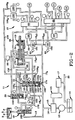
The present invention is particularly suited
for use in combination with the transmission shift
fork control mechanism identified generally by the
numeral 11 (Figure 1) herein.
To facilitate an understanding of the
present invention, the shift fork control mechanism 11
includes means for providing a source of pressurised
hydraulic fluid, such as a pump 12, that may be driven
by an engine (not shown) through a conventional torque
converter and power transmission assembly -- the
combination torque converter and transmission assembly
being identified generally by the numeral 13. A
countershaft type transmission, such as that shown in
the aforesaid US Patent No. 5,009,116, may be driven
by the torque converter in a conventional manner. The
pump 12 delivers fluid from a reservoir 14 to a
conventional regulator valve 15 which establishes the
maximum pressure for the hydraulic fluid delivered by
the main feed conduit 16. After the pressure
requirement in the main feed conduit 16 is
established, the excess fluid is directed to the
torque converter and power transmission assembly 13,
as well as to a conventional lubrication and cooling
system 17, as is well known to the prior art.
The main feed conduit 16 is in fluid
communication with a manual range selector valve 18
and a branch feed conduit 16A. The branch conduit 16A
feeds lateral subbranch feed conduits 16A1, 16A2, 16A3
and 16A4. Lateral subbranch feed conduit 16A2 is
bifurcated to provide two conduits that communicate
with shift fork controller 19. The manual range
selector valve 18 selectively controls the shift fork
controller 19 via either a forward flow control valve
20 or a reverse flow control valve 21.
The lateral feed branch 16A1 incorporates a
normally closed on/off inhibit control solenoid valve
22 that selectively supplies hydraulic fluid against a
control drive plug 23 in the reverse flow control
valve 21. This provision for supplying hydraulic
pressure selectively to translate the plug 23 in the
reverse flow control valve 21 is intended to provide a
means by which to effect a forward-to-reverse
inhibiting function, and its operation will be
hereinafter more fully described.
Suffice it to say that when the manual range
selector valve 18 is disposed in the forward drive
range D, as depicted on Figure 1, pressurised
hydraulic fluid provided by the pump 12 will be
delivered to the feed conduits 16 at a controlled
pressure, as determined by regulator 15. The
regulated line pressure is then directed through
manual selector valve 18, to and through the forward
flow control valve 20, along branch feed passage 106C,
and, by a high pressure selector shuttle valve 107,
into feed passage 106 to supply the hereinafter
described control valving mechanism 10.
When the manual range selector valve 18 is
moved from neutral N to the forward drive range D
pressurised fluid from the forward flow control valve
20 positions the shift fork controller 19 in the
forward drive range, as depicted in Figure 1. The
shift fork controller 19 may actuate a synchroniser
(not shown), as by the control fork 24 that is
translated by the shift fork controller 19. It should
be appreciated that if a synchroniser is not employed,
the control 10 can be utilised to provide the on-going
and off-going pressures required to activate the
torque transfer devices used with a planetary gear
set.
The termination of feed branch 16A is
bifurcated into two lateral subbranch feed conduits
16A3 and 16A4 which communicate, respectively, with
the first and second, normally closed, on/off solenoid
control valves 25 and 26. The first, normally closed,
on/off solenoid control valve 25 communicates with a
first two-position shuttle valve 28 via a feed passage
29. As can best be seen in Figures 3-8, the first
two-position shuttle valve 28 has a housing 30 with an
axially oriented interior bore 31. A shuttle member
32, which is preferably provided with spacer stubs 33A
and 33B that protrude axially outwardly from the
opposite ends of the shuttle member 32, reciprocates
within the plugged bore 31. The shuttle member 32,
and particularly by virtue of the interaction of the
axially protruding spacer stubs 33A and 33B with the
housing 30 and its associated plug structure, defines
first and second chambers 34 and 35, respectively,
within the valve bore 31, as will be hereinafter more
fully described.
Continuing with a description of the first
two-position shuttle valve 28, the feed passage 29
communicates with the first chamber 34 through an
annular port 36. The first chamber 34 is continually
accessible to any pressurised fluid received within
the port 36 inasmuch as the spacer stub 33A engages
the plug 39 in such a way as to assure that
pressurised fluid introduced through port 36 will be
immediately accessible to the chamber 34. A
structural spacer stub is provided at each end of the
shuttle member 32 in the first two-position shuttle
valve 28 as well as at each end of the shuttle member
48 in the second two-position shuttle valve 40.
The first chamber 34 in the first shuttle
valve 28 selectively communicates with a control
conduit 38 through annular port 39. The second
chamber 35 in shuttle valve 28 communicates with the
second two-position shuttle valve 40 through a cross
feed passage 41 that opens though an annular port 42
in the second chamber 35 of the first shuttle valve
28.
The second two-position shuttle valve 40
also has a housing 43 with an axially oriented
interior bore 44. A shuttle member 45 reciprocates
within the plugged bore 44. The shuttle member 45
defines first and second chambers 46 and 48 within the
bore 44. The cross feed conduit 41 communicates with
the first chamber 46 in the second shuttle valve 40
through an annular port 49. A signal conduit 50
similarly communicates with the first chamber 46 in
the second shuttle valve 40, also through the annular
port 49.
A spring-assist conduit 52 communicates with
the bore 44 in the second shuttle valve 40 through an
annular port 53. The spring-assist conduit 52 will
communicate with either the first or the second
chamber 46 or 48 depending upon the position of the
shuttle member 45 within the bore 44, as will become
hereinafter more fully explained in conjunction with
the operation of the control 10. A blocking signal
conduit 54 also communicates with the second chamber
48 through an annular port 55.
A first two-position spool valve is
designated generally by the numeral 60. The spool
valve 60 is comprised of a housing 61 which defines an
axially oriented bore 62. A spool member 63, having a
plurality of axially spaced radially extending lands
64, is disposed within the bore 62 for axial
reciprocation. A first subchamber 65A is defined
between axially spaced lands 64A and 64B; a second
subchamber 65B is defined between axially spaced lands
64B and 64C; and a third subchamber 65C is defined
between axially spaced lands 64C and 64D.
Additionally, a control chamber 66 is defined between
the land 64D and the end face 68 of bore 62.
The spool member 63 is biased within the
bore 62 to the spring-set position depicted in Figures
4 and 5, principally by virtue of a spring member 69
that acts between the land 64A and a reaction/closure
plate 70 retained within the open end of the bore 62
by an anchor pin 71. The reaction/closure plate 70
also serves to define a spring-assist chamber 72
between it and the land 64A. A locating stub shaft 73
extends axially outwardly from the reaction/closure
plate 70 to be engaged by the protruding end 74 of the
shaft portion 75 when the spool member 63 is in the
pressure-set position, depicted in Figures 3 and 6
through 8. As such, it must be appreciated that the
engagement of the locating stub shaft 73 with the
protruding end 74 defines the pressure-set position of
the spool member 63. It should also be appreciated
that the shaft portion 75 and the lands 64 comprise
the spool valve member 63.
The control conduit 38 communicates with the
control chamber 66 through an annular port 76. The
control chamber 66 also communicates with a pressure
sensor 78 through a signal passage 79 -- when the
spool valve member 63 is in the pressure-set position,
depicted in Figures 3 and 6 through 8 -- that is fed
through an annular port 80. The first/fifth drive
ratio conduit 82 communicates with the bore 62 through
an annular port 83. The specific subchamber 65 with
which the various conduits and passages communicate
will vary depending upon the position of the spool
valve member 63, and for that reason, a discussion of
the specific communication path through the spool
valve 60 will be deferred until the operation of the
control valving mechanism 10 is described. At this
point, therefore, it shall only be noted that the
first/fifth drive ratio conduit 82 also communicates
with a second spool valve 85, as will be hereinafter
more fully described.
The spring-assist chamber 72 communicates
with a signal conduit 86, and the signal conduit 86,
in turn, communicates with a signal control subchamber
87 in the reverse flow control valve 21 (Figures 1, 2
and 9). The signal conduit 86 also communicates with
a pressure sensing switch 88. The pressure sensing
switch 88 supplies a "reverse" operation signal for
the shift fork control mechanism, and it serves the
additional function of signalling a forward/reverse
range inhibit state for the first spool valve 60 in
the present control 10 as is more fully described in
conjunction with Figure 10.
A hydraulic return system 90 -- which
directs hydraulic fluid back to the reservoir 14
(Figure 1) -- communicates with the bore 62 at two
axially spaced locations. Specifically, two drain or
exhaust conduits 91 and 92 effect communication
between the return system 90 and the bore 62 at
annular ports 93 and 94, respectively. The first
three-way modulating solenoid valve 100 also
communicates with the bore 62 through a transfer
conduit 101 that opens to an annular port 102 which
circumscribes the axial bore 62. The first three-way
modulating solenoid valve 100 also communicates with
the return system 90 through an exhaust conduit 103.
The first three-way modulating solenoid
valve 100, as well as a second three-way modulating
solenoid valve 105, are supplied with hydraulic fluid
at substantially the line pressure provided to the
manual range selector valve 18 by the main feed
conduit 16. Specifically, line pressure is
selectively fed through the manual range selector
valve 18 to the forward or reverse flow control valves
20 or 21, respectively, and through one or the other
of the flow control valves 20 or 21 to the feed
passage 106. The solenoid feed passage 106 thereby
provides hydraulic fluid at line pressure to the
three-way modulating solenoid valves 100 and 105
through the respective branch feed passages 106A and
106B. In the prior art arrangement, the feed passage
106 connects directly with the forward and reverse
flow valves 20 and 21, but the control valving
mechanism 10 embodying the concepts of the present
invention requires the incorporation of a shuttle
valve which selectively connects one of the other of
the flow control valves 20 and 21 to the feed passage
106. Hence, as depicted in Figures 1, 2 and 9, the
high pressure selector shuttle valve 107 is provided
at the intersection of the feed passage 106 with the
branches 106C and 106D -- branch 106C connecting the
forward flow control valve 20 to the high pressure
selector shuttle valve 107, and branch 106D connecting
the reverse flow control valve 21 to the high pressure
selector shuttle valve 107.
To conclude the structural description of
the first two-position spool valve 60, the
third/reverse drive ratio conduit 108 communicates
with the bore 62 through an annular port 109. Here,
too, the specific subchamber 65 with which the
third/reverse drive ratio conduit 108 will communicate
during the operation of the control valving mechanism
10 will be hereinafter fully described in conjunction
with the explanation as to the operation of that
mechanism.
The second two-position spool valve 85 is
also comprised of a housing 110 which defines a
cylindrical bore 111. A spool member 112, having a
plurality of axially spaced, radially extending lands
113 is disposed within the cylindrical bore 111 for
axial reciprocation. A first subchamber 115A is
defined between the lands 113A and 113B; a second
subchamber 115B is defined between lands 113B and
113C; a third subchamber 113C is defined between lands
113C and 113D; a fourth subchamber 115D is defined
between lands 113D and 113E; and, a fifth subchamber
115E is defined between lands 113E and 113F.
Additionally, a control chamber 116 is defined between
the land 113F and the end face 118 of bore 111.
The spool member 112 is biased within the
bore 111 to the spring-set position, depicted in
Figures 5-8, by the action of a spring member 119 that
acts between land 113A and a reaction/closure plate
120 which is, in turn, retained within the open end of
the cylindrical bore 111 by an anchor pin 121. The
reaction/closure plate 120 also serves to define one
wall of a spring-assist chamber 122 which extends
between the land 113A and the reaction/closure plate
120.
A locating stub shaft 123 extends axially
outwardly from the reaction/closure plate 120 to be
engaged by the protruding end 124 of the shaft portion
125 of the second spool valve member 112 when the
spool valve member 112 is in the position depicted,
for example, in Figure 3. Thus, engagement of the
locating stub shaft 123 with the protruding end 124
defines the pressure-set position of the spool valve
member 112.
The spring-assist conduit 52 communicates
with the spring-assist chamber 122 through an annular
port 126. The hydraulic return system 90 communicates
with the bore 111 at three axially spaced locations
through exhaust conduits 130, 131 and 132 that open
into the bore 111 through annular exhaust ports 133,
134 and 135, respectively.
The feed conduits 138, 139, 140 and 141 for
the hydraulic torque transfer devices C1, C2, C4 and
C5, respectively, communicate individually with the
bore 111 of the second spool valve 85 through their
respective annular ports 142, 143, 144 and 145. A
sensor 146 communicates with the control chamber 116
in bore 111 by a signal conduit 148 that opens through
an annular port 149.
The blocking signal conduit 54, which opens
to chamber 48 in the second two-position shuttle valve
40 through annular port 55, also communicates with the
bore 111 in the second spool valve 85 through the
annular port 144. The signal conduit 50 -- which
opens to chamber 46 in the second two-position shuttle
valve 40 through annular port 51 -- also communicates
with the bore 111 in the second spool valve 85 through
annular port 145.
The first/fifth drive ratio feed conduit 82,
which communicates with the bore 62 in the first spool
valve 60 through annular port 83, also communicates
with the bore 111 in the second spool valve 85, as
through the annular port 150.
The second, normally closed, on/off solenoid
control valve 26 communicates with the control chamber
116 in the second spool valve 85 via feed passage 151
that opens into the bore 111 through annular port 152.
The second three-way modulating solenoid
valve 105 communicates with the bore 111 in the second
spool valve 85 through a transfer conduit 153 that
opens into an annular port 154. The second three-way
modulating solenoid valve 105 also communicates with
the return system 90 through exhaust conduit 155.
Before embarking on a description as to the
operation of the control valve mechanism 10 to which
the present invention is directed, it should be
understood that the explanation begins with a
recapitulation as to the hydraulic fluid flow
accomplished by positioning the manual range selector
valve 18 in the forward drive P position (Figures 1
and 2). Specifically, the regulated line pressure fed
from the pump 12 through the main feed conduit 16
passes through the manual range selector valve 18,
through the forward flow control valve 20, along
branch feed passage 106C and into feed passage 106, as
permitted by the high pressure response of the
selector shuttle valve 107. The pressurised hydraulic
fluid is then presented at both the first and second
three-way modulating solenoid valves 100 and 105
through branch passages 106A and 106B, respectively.
The previously described flow is achieved by
virtue of the shift fork controller 19 having been
disposed in the forward set position, depicted in
Figure 1, such that the hydraulic fluid passing
through branch 16A at regulated line pressure will not
only be available at the respective first and second
on/off solenoid control valves 25 and 26, but will
also have passed into lateral subbranch 16A1 to feed
the normally closed, on/off solenoid inhibit valve 22,
as well as into the lateral subbranch 16A2 which
accesses conduit 156 through the shift fork controller
19. Conduit 156 feeds the control chamber 159 in the
forward control valve 20, whereby that valve is
activated to permit the flow of pressurised hydraulic
fluid through the forward flow control valve 20, as
previously described.
It should also be noted that each of the
on/off solenoid valves 22, 25 and 26 also communicate
with the return system 90, as through the respective
exhaust conduits 160, 161 and 162 when the referenced
valve 22, 25 and/or 26 is in the "off" or
hydraulically closed state. The three-way modulating
solenoid valves 100 and 105 similarly communicate with
the return system 90 through exhaust conduits 103 and
155, respectively. Thus, when either of the three-way
modulating solenoid valves 100 or 105 are closed, the
transfer conduits 101 or 153 communicating with the
closed three-way modulating solenoid valves 100 and/or
105, respectively, will communicate through the closed
modulating solenoid valve with the return system 90.
For ease of viewing, the pressurised
conduits and passages have been stippled, and that
same convention will be employed in the remainder of
the explanation to follow.
Finally, some attention should also be
directed to the forward-to-reverse, normally off,
on/off solenoid inhibit valve 22 and its interaction
with a uniquely modified reverse flow control valve
21. A full understanding of the interaction between
the inhibit valve 22 and the reverse flow control
valve 21 is particularly important inasmuch as the
solenoid inhibit valve 22 is hydraulically open or
"on" during operation of the second through the fifth
drive ratios in the forward drive range D in order to
preclude inadvertent shifting into the reverse drive
range R. As such, operatively shifting into the
reverse range R can only be accomplished from either
the first drive ratio in the forward drive range D,
the neutral position N or the park position P of the
manual range selector valve 18.
It should be observed that the unique
reverse flow valve 21 has a housing 165 which defines
a cylindrical bore 166. A spool member 168, having a
plurality of axially spaced radially extending lands
169, is disposed within the bore 166 for axial
reciprocation. A first subchamber 170A is disposed
between lands 169A and 169B, and a second subchamber
170B is disposed between lands 169B and 169C.
The control plug 23 is disposed in axial
alignment with the spool member 168, and the control
plug 23 also reciprocates axially within the bore 166.
The signal control subchamber 87 is located between
the land 169C and the plug 23, and the signal conduit
86 communicates with the signal control subchamber 87.
A control subchamber 171 is disposed between the plug
23 and the opposed end wall 172 of the housing 165,
and the branch conduit 16A1 communicates with the
control subchamber 171. The spool member 168 is
biased within bore 166 to a spring-set position by
virtue of a compression spring 173 that is retained
within the open end 174 of the bore 166, as by a
transversely oriented retainer pin 175.
Without actuation of the normally closed
on/off solenoid inhibit valve 22, the reverse flow
control valve 21 is spring-set to the position
depicted in Figure 1, such that when the manual range
selector valve 18 is positioned in the reverse range
R, pressurised hydraulic fluid flows from the main
feed conduit 16 through the manual range selector
valve 18 into the reverse supply conduit 176 to the
reverse flow control valve 21 and through the flow
control valve 21 into the reverse fork actuation
passage 178. The reverse fork actuation passage 178
supplies pressurised hydraulic fluid into the reverse
chamber 179 in the shift fork controller 19. As the
shift fork controller is moved to the reverse position
(Figure 9), pressurised hydraulic fluid is introduced
into the signal conduit 86, which supplies the signal
control subchamber 87.
The presence of pressurised fluid within the
signal control subchamber 87 serves to effect axial
separation of the spool member 168 from the control
drive plug 23 which permits the pressurised fluid in
the reverse supply conduit 176 to pass through the
reverse flow control valve 21 and into the feed
passage branch 106D, as depicted in Figure 2. With
the forward flow control valve 20 in the spring-set
position, the pressurised fluid in the feed passage
branch 106D will actuate the selector shuttle valve
107 to permit flow from the feed passage branch 106D
into feed passage 106, as represented in either Figure
2 or 9. Thus, the reverse flow control valve 21
initially directs pressurised hydraulic fluid from the
manual range selector valve 18 to the shift fork
controller 19 in order to establish the reverse drive
range. After the reverse range is established, the
pressurised fluid is directed to the feed passage 106
for supplying the modulating, solenoid valves 100 and
105.
The solenoid inhibit valve 21 is, as will be
hereinafter more fully apparent, activated in
conjunction with selected drive ratios in the forward
drive range. In the spring-set position of the
reverse flow control valve 21 it will, as described in
the previous paragraph, direct fluid flow from the
manual selector valve 18 to the reverse chamber 179 in
the shift fork controller 19, and in response to the
resulting positioning of the shift fork controller 19
in the reverse position, pressurised fluid is returned
to the signal control subchamber 87 in the reverse
flow control valve 21 so that the flow control valve
21 will supply pressurised hydraulic fluid to the feed
passage 106. However, when the inhibitor valve 22 is
opened -- i.e.: turned hydraulically "on" -- pressurised
fluid will flow through the inhibitor
valve 22 and into the control subchamber 171 and
translate the control drive plug 23 downward to
establish a pressure set position for the reverse flow
control valve 22, even when the shift fork controller
19 is in the forward position depicted in Figures 1
and 2.
As a result, should the vehicle operator
move the manual selector valve 18 to the reverse
position when the control valving mechanism 10 is in
any of the second through the fifth drive ratios, the
inhibit valve 21 will divert flow into the feed
passage 106 rather than permit the shift fork
controller 19 to be moved into the reverse drive
position. Hence, even though the pressurised fluid
will be flowing through the reverse flow control valve
21 rather than the forward flow control valve 20, the
fluid will still be applied to the modulating solenoid
valves 100 and 105. Inasmuch as the pressure sensor
88 is not activated under that condition, the logic
circuit (not shown) will not alter the state of the
forward drive ratio and pressurised hydraulic fluid to
the torque transfer device will only be interrupted
for the infinitesimally short time it takes for the
operator to have moved the manual range selector valve
18 from the forward drive range D to the reverse drive
range R. A return to the neutral N, park P or forward
drive range position D of the manual range selector
valve 18 will rectify the error.
In the neutral N position of the manual
range selector valve 18, the middle land 180 of the
manual range selector valve 18 blocks the flow of
pressurised hydraulic fluid into or through the valve
18.
By way of background, it should be
understood that motor vehicle transmissions generally
include selectively engageable gear elements for
providing multiple forward speed or drive ratios
through which the output torque of the engine is
applied to the drive wheels of the vehicle. In
automatic transmissions, the gear elements which
provide the various drive ratios are selectively
activated, as through fluid operated torque transfer
friction devices, such as clutches and brakes. Thus,
shifting from one drive ratio to another, generally
involves releasing (disengaging) the torque transfer
device(s) associated with the current drive ratio and
applying (engaging) the torque transfer device(s)
associated with the successive drive ratio. Any
torque transfer device to be released during a
particular shift sequence is conventionally referred
to as the off-going torque transfer device, while the
torque transfer device to be applied during that same
shift sequence is referred to as the on-coming torque
transfer device. There is generally a slight overlap
between the "release" and "apply" of the torque
transfer devices involved in a shift sequence, and
high quality shifts are achieved only when the
"release" and "apply" operations are properly timed
and executed.
Conventionally, the shifting control
effected by an automatic transmission is performed in
conjunction with a logic control map and various
inputs which reflect such system parameters as vehicle
speed, engine throttle position and engine torque.
Fluid pressure signals representative of the various
system parameters are processed in an on-board
computer and/or microprocessor to determine when a
shift is in order and to actuate, in accordance with
the logic control map, electronically controlled
valves in the hydraulic control system which respond
to the signals received from the computer to effect
the required engagement and/or disengagement (and in
the proper order) of the appropriate torque transfer
devices necessary to secure the desired drive ratio
changes to the output shaft of the transmission.
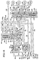
Actuation of the First Drive Ratio
The first drive or gear ratio is available
after the manual range selector valve 18 has been
shifted from the neutral N to the forward drive D
range position, as depicted in Figure 1, which makes
the pressurised hydraulic fluid available at the first
and second modulating solenoid valves 100 and 105.
The first drive range is established by actuating the
on-going torque transfer friction device C1. With
particular reference to Figure 3, it can be seen that
the first drive ratio torque transfer device C1 is
properly actuated when both the first and second
on/off solenoid shift control valves 25 and 26, as
well as the first three-way modulating solenoid valve
100, are in the hydraulically "on" state. The second
three-way modulating solenoid valve 105, however, is
in the hydraulically "off" state. As such, the flow
of hydraulic fluid at substantially line pressure is
directed through the first, normally closed, on/off
solenoid control valve 25 and into the first chamber
34 of the first two-position shuttle valve 28 via the
feed passage 29. The shuttle member 32 is thereby
translated into the position depicted in Figure 3, if
it is not already in that position. With the shuttle
member 32 so positioned -- which is depicted as the
"down" position -- the pressurised hydraulic fluid is
permitted to pass through chamber 34 and the control
conduit 38 into the control chamber 66 in the first
two-position spool valve 60, as represented by the
stippling of the pressurised portions. When
sufficient fluid pressure is established within the
control chamber 66 to overcome the biasing action of
the spring member 69, the spool member 63 is
translated into the pressure-set position depicted in
Figure 3.
Simultaneously, the flow of hydraulic fluid
at substantially line pressure, also represented by
the stippling on Figure 3, is directed through the
second, normally closed, on/off solenoid shift control
valve 26, along the feed passage 151 and into the
control chamber 116 of the second two-position spool
valve 85, as is also represented by stippling the
pressurised portions. When sufficient fluid pressure
is established in the control chamber 116 to overcome
the biasing pressure of the spring member 119, the
spool member 112 is translated into the pressure-set
position depicted in Figure 3.
The pressure-set position of the spool
member 63 in the first spool valve member 60 allows
pressurised hydraulic fluid in control chamber 66 to
activate pressure sensor 78, and the pressure-set
position of the spool member 112 in the second spool
valve 85 allows the pressurised hydraulic fluid within
control chamber 116 to activate pressure sensor 146.
Pressure sensor 88 remains deactivated. Pressure
activation of both sensors 78 and 146 signals the
customarily employed logic circuit in the on-board
computer and/or microprocessor (not shown) that the
control valving mechanism 10 is disposed appropriately
for operation within the first, and also for shifting
to, the second drive ratio, as will be hereinafter
described. The hydraulic state of the on/off solenoid
shift control valves 22, 25 and 26, the hydraulic
state of the three-way modulating solenoid valves 100
and 105, as well as the hydraulic state of the
pressure sensing switches 78, 88 and 146, are depicted
in the logic table represented in Figure 11. The x
designation on the logic table indicates that the
solenoid and/or the solenoid valve so designated is
hydraulically "on". Similarly, the x designates that
the pressure sensor is pressurised.
With the first and second spool valves 60
and 85, respectively, both in the pressure-set
position, pressurised hydraulic fluid is directed from
the branch feed passage 106A through the open first
three-way modulating solenoid valve 100 along the
transfer conduit 101 and into the subchamber 65B,
through annular port 102, in the first spool valve 60.
From subchamber 65B in the first spool valve 60, the
pressurised hydraulic fluid is transmitted through the
first/fifth drive ratio conduit 82 and into subchamber
115D in the second spool member 85 through the annular
port 150. From the subchamber 115D, the pressurised
hydraulic fluid passes outward, through annular port
142, and along feed conduit 138 to activate the torque
transfer device C1 which effects operation of the
first drive ratio.
As should be apparent, the particular
disposition of the spool valves 60 and 85, with only
the first three-way modulating solenoid valve 100
hydraulically open, permits hydraulic fluid only to
activate the first drive ratio torque transfer device
C1. Upshifting out of the first drive ratio may be
accomplished by turning the first modulating solenoid
valve 100 "off." With the first solenoid valve turned
off, the pressurised hydraulic fluid in torque
transfer device C1 backflows along the first drive
ratio conduit 138, through subchamber 115D in the
second spool valve 85, along the first/fifth drive
ratio conduit 81 and through subchamber 65B in the
first two-position spool valve 60. From subchamber
65B, the pressurised hydraulic fluid passes through
transfer conduit 101 into the first modulating
solenoid valve 100 to exit into the return system 90
through exhaust conduit 103.
In any event, once the aforesaid shift to
the first drive ratio is completed -- but only after
the on-board computer and/or microprocessor has
signalled (as a part of the pre-shift logic) that
preparation for the shift from the first to the second
drive ratio should be instituted -- the inhibit
solenoid is turned "on", as depicted in Figure 2.
Turning the inhibit solenoid 22 "on", as was
previously described, precludes a shift from the
second drive ratio in the forward drive range directly
into the reverse drive range.
Actuation of the Second Drive Ratio
The second drive ratio is established with
the control valving mechanism 10 disposed as depicted
in Figure 3. That is, the on-going torque transfer
device C2 is engaged, and the off-going torque
transfer device C1 is substantially simultaneously
disengaged, although, as previously noted, a slight
overlap is generally deemed desirable, as is well
known to the art. This sequencing from the first to
the second drive ratio is controlled by opening the
second three-way modulating solenoid valve 105 to
engage the torque transfer friction device C2 and
closing the first three-way modulating solenoid valve
100 to effect depressurisation of the torque transfer
device C1.
Closure of the three-way modulating solenoid
valve 100 permits depressurisation of the torque
transfer device C1 at a predetermined rate. When
valve 100 closes, the pressurised fluid within the
torque transfer device C1 flows back through the
chamber 115B in the second spool valve 85, along the
first/fifth conduit 82 and through chamber 65B in the
first spool valve 60 and into the first modulating
solenoid valve 100 by transfer conduit 101. The
exhaust conduit 103 communicates between the transfer
conduit 101 and the return system 90 when the first
modulating solenoid valve 100 is closed. At this
point in the operation of the control valving
mechanism 10, all components thereof are disposed as
depicted in Figure 3.
Opening the second three-way modulating
solenoid valve 105 permits the flow of pressurised
hydraulic fluid to pass from the branch feed passage
106B into the control mechanism 10. Specifically,
fluid flow is directed from the second three-way
modulating solenoid valve 105 via the transfer conduit
153 into subchamber 115B through annular port 154.
The subchamber 115B is now in fluid communication with
the torque transfer friction device C2 through the
second drive ratio feed conduit 139, which
communicates with subchamber 115B through annular port
143. The pressurised hydraulic fluid admitted to the
control valving mechanism 10 through the second
three-way modulating solenoid valve 105 thus activates
the second drive ratio.
The line pressures described to actuate
torque transfer friction device C2 by opening the
second modulating solenoid 105 are depicted by the
stippling in Figure 4. Before discussing Figure 4,
however, it can be observed that with the components
disposed as depicted in Figure 3, one can also effect
a downshift simply by closing the second modulating
solenoid valve 105 and opening the first modulating
solenoid valve 100.
Once the aforesaid shift to the second drive
ratio is completed -- but only after the on-board
computer and/or microprocessor has signalled (as a
part of the pre-shift logic) that preparation for the
shift from the second to the third drive ratio should
be instituted -- the first solenoid valve 25 is turned
"off" so that the passage of hydraulic fluid
therethrough is precluded. However, the second
solenoid valve 26 remains in the "on" state so that
the passage of pressurised hydraulic fluid
therethrough is maintained.
Turning the first solenoid valve 25 "off"
causes the hydraulic fluid in control chamber 66,
particularly in response to the biasing action of
spring 69, to backflow through control conduit 38 into
and through the first chamber 34 in the first shuttle
valve 28 and then through feed passage 29 into the
first solenoid valve 25. From the solenoid valve 25,
the fluid exits into the return system 90 through
exhaust conduit 161. The first two-position spool
valve 60 thus returns to the spring-set position
(Figure 4).
Returning to the spring-set position of the
spool member 63 in the first spool valve member 60
precludes further pressurisation of control chamber
66, and thus the pressure sensor 78 is no longer
activated. On the other hand, the pressure-set
position of the spool member 112 in the second spool
valve 85 allows the pressurised hydraulic fluid within
control chamber 116 to maintain the activation of
pressure sensor 146. Pressure sensor 88 remains
deactivated. The activation of only sensor 146
signals the customarily employed logic circuit in the
on-board computer and/or microprocessor (not shown)
that the control valving mechanism 10 is disposed
appropriately for continued operation within the
second drive ratio and also for shifting to the third
drive ratio, as will be hereinafter described. The
hydraulic state of the on/off solenoid control valves
22, 25 and 26, the hydraulic state of the three-way
modulating solenoid valves 100 and 105, as well as the
hydraulic state of the pressure sensing switches 78,
88 and 146 for the second drive ratio, are also
depicted in the logic table represented in Figure 11.
Thus, before the shift to the third drive
ratio can be accomplished, the control valving
mechanism 10 must be in the state represented by
Figure 4.
Providing a detailed description of the
preparation for the second-to-third ratio shift at
this location in the overall description, serves to
emphasise that the position of the spool valve member
63 is irrelevant when operating in the second drive
ratio, inasmuch as the off-going pressure from the
torque transfer friction device C1 exhausts through
the first spool valve 60, irrespective of the position
of the valve member 63. That is, if the first spool
valve 60 is in the spring-set position, hydraulic
fluid in the torque transfer device C1 will exit to
the return system 90 through the exhaust conduit 91,
as indicated by the arrows on Figure 4. But even if
the first spool valve 60 were pressure-set, the
hydraulic fluid in the torque transfer device C1 would
exit to the return system 90 through the exhaust
conduit 103.
As a prerequisite to the shift into the
third drive ratio it should be noted that the inhibit
solenoid valve 22 remains hydraulically "on" to
preclude a direct shift from the third drive ratio in
the forward drive range to the reverse range.
Actuation of the Third Drive Ratio
The third drive ratio is established with
the control valving mechanism 10 disposed in
accordance with the representation in Figure 4. That
is, the on-going torque transfer device C3 is engaged
and, in appropriate coordination therewith, the
off-going torque transfer device C2 is disengaged.
This sequencing from the second to the third drive
ratio is controlled by opening the first modulating
solenoid valve 100 to engage torque transfer device C3
and closing the second modulating solenoid valve 105
to effect depressurisation of the torque transfer
device C2 at a predetermined rate in order to effect
the desired overlap.
When the second modulating solenoid valve
105 closes, the pressurised fluid within the torque
transfer device C2 flows back along the second drive
ratio conduit 139, through chamber 115B in the second
spool valve 85, and along the transfer conduit 153 to
enter the return system 90 through the exhaust conduit
155, as shown in Figure 4.
Opening the first modulating control valve
100 permits the flow of pressurised fluid to pass from
the branch feed passage 106A into the control valving
mechanism 10. Specifically, the fluid flow is
directed from the first modulating solenoid valve 100
via the transfer conduit 101 into subchamber 65B in
the first spool valve 60. The subchamber 65B is now
in fluid communication with the torque transfer device
C3 through the third/reverse drive ratio conduit 108.
The pressurised hydraulic fluid admitted to the
control valving mechanism 10 through the first
modulating solenoid valve 100 thus activates the third
drive ratio.
The line pressure described to actuate the
torque transfer device C3 by opening the first
modulating solenoid 100 is depicted by the stippling
in Figure 5. Before discussing Figure 5, however, it
can be observed that with the components disposed as
depicted in Figure 4, one can also effect a downshift
from the third to the second drive ratio simply by
closing the first modulating solenoid valve 100 and
opening the second solenoid valve 105. It should also
be appreciated that the position of the spool member
112 is irrelevant when operating in the third drive
ratio of the forward range, inasmuch as the off-going
pressure from the torque transfer device C2 exhausts
through the second spool valve 85 in either position
of the spool member. That is, the hydraulic fluid
exits to the return system 90 through exhaust conduit
155 if the stool member 112 is in the pressure-set
position, or through exhaust conduit 130 if the spool
member 112 is in the spring-set position.
Once the aforesaid shift to the third drive
ratio is completed -- but only after the on-board
computer and/or microprocessor has signalled (as a
part of the pre-shift logic) that preparation for the
shift from the third to the fourth drive ratio should
be instituted -- the second on/off shift control
solenoid valve 26 is turned "off" so that the passage
of hydraulic fluid therethrough is precluded (Figure
5).
Turning the second solenoid valve 26 "off"
causes the hydraulic fluid in control chamber 116,
particularly in response to the biasing action of
spring 119, to backflow through feed passage 151 into
the second solenoid valve 26. From the second
solenoid valve 26 the fluid exits into the return
system 90 through exhaust conduit 162.
With both shift control solenoids 25 and 26
closed, both the first and second spool valves 60 and
85 revert to the spring-set position, as depicted in
Figure 5.
Here, too, the solenoid inhibit valve 22
remains "on", and the sensor 88 is not pressurised.
Under these conditions, and with both spool valves 60
and 84 in the spring-set position, activation of
either sensor 78 or 146 is precluded. The lack of
activation by either sensor 78 or sensor 146 signals
the customarily employed logic circuit (not shown)
that the control valving mechanism 10 is disposed
appropriately for continued operation in the third
drive ratio and subsequent actuation of the fourth
drive ratio. That is, before the fourth drive ratio
can be accomplished, the control valving mechanism 10
must be in the state represented in Figure 5.
The hydraulic state of the on/off solenoid
control valves 22, 25 and 26, the hydraulic state of
the three-way modulating solenoid valves 100 and 105,
as well as the hydraulic state of the pressure sensing
switches 78, 88 and 146, are depicted in the logic
table represented in Figure 11.
Actuation of the Fourth Drive Ratio
The fourth drive ratio is established with
the control valving mechanism 10 disposed in
accordance with the representation in Figure 5. That
is, the on-going torque transfer device C4 is engaged
and, in appropriate coordination therewith, the
off-going torque transfer device C3 is disengaged.
This sequencing from the third to the fourth drive
ratio is controlled by opening the second three-way
modulating solenoid valve 105 so that pressurised
hydraulic fluid can pass from the branch passage 106B
into the control valving mechanism 10. Specifically,
fluid flow is directed from the second three-way
modulating solenoid valve 105 via the transfer conduit
153 into subchamber 115B through annular port 154.
The subchamber 115B is now in fluid communication with
the torque transfer friction device C4 through the
fourth drive ratio feed conduit 140, which
communicates with subchamber 115B through annular port
144. The pressurised hydraulic fluid admitted to the
control valving mechanism 10 through the three-way
modulating solenoid valve 105 thus activates the
fourth drive ratio.
Closing the first three-way modulating
solenoid valve 100 allows the pressurised hydraulic
fluid in the torque transfer device C3 to backflow
along the third/reverse drive ratio conduit 108 and
through the subchamber 65B in the first spool valve 60
and along the transfer conduit 101 into the first
modulating solenoid valve 100. From the first
modulating solenoid valve 100, the fluid exits into
the return system 90 through exhaust conduit 103.
The line pressure described to actuate the
torque transfer device C4 by opening the second
modulating solenoid valve 105 is depicted by the
stippling in Figure 6. Before discussing Figure 6,
however, it can be observed that with the components
disposed as depicted in Figure 5, one can also effect
a downshift from the fourth drive ratio to the third
drive ratio simply by closing the second modulating
solenoid 105 and opening the first modulating solenoid
100. Thus, the position of the spool member 63 is
irrelevant when operating in the fourth drive ratio of
the forward drive range inasmuch as the off-going
pressure from torque transfer device 63 exhausts
through the first spool valve 60 in either position of
the spool member 63. That is, the hydraulic fluid
exits to the return system 90 through exhaust conduit
92, as shown by the arrows in Figure 6, if the spool
member 63 is in the pressure-set position or through
exhaust conduit 103 if the spool member 63 is in the
spring-set position (Figure 5).
In order to prevent undesirable shifting
combinations -- such as a shift from the fourth to the
second drive ratio when the appropriate synchronisers
are mounted on the same shaft -- means have been
incorporated to assure that such a shift will not be
possible. To that end, the present control 10
utilises a hydraulic interlock -- i.e.:
pressurisation of the spring assist chamber 122, as is
also depicted on Figure 6. Specifically, the
pressurised hydraulic fluid received in subchamber
115B to actuate the torque transfer device C4 is also
transferred, through blocking signal conduit 54, into
chamber 48 in the second shuttle valve 40. The
blocking signal conduit 54 opens into chamber 48
through port 55. The pressurisation of chamber 48
causes the shuttle member 45 to move "upwardly", as
viewed in Figure 6, such that the chamber 48 will
communicate with one end of the spring-assist conduit
52, through port 53. The other end of the
spring-assist conduit 52 communicates with the
spring-assist chamber 122, as through port 126.
Pressurisation of the spring-assist chamber 122 forces
the spool member 112 to remain in the spring-set
position, thereby precluding the passage of
pressurised hydraulic fluid into the second drive
ratio torque transfer device C2. This arrangement
thereby precludes a fourth-to-second shift.
Once the aforesaid shift to the fourth drive
ratio is completed -- but only after the on-board
computer and/or microprocessor has signalled (as a
part of the pre-shift logic) that preparation for the
shift from the fourth to the fifth drive ratio should
be instituted -- the first on/off shift control
solenoid 25 is turned "on", as depicted in Figure 6,
so that pressurised hydraulic fluid can flow
therethrough, and the second on/off shift control
valve 26 is turned "off" so that the passage of
hydraulic fluid therethrough is precluded.
Turning the first on/off solenoid control
valve 25 "on" causes the pressurised hydraulic fluid
to pass from the first control valve 25 along the feed
passage 29 and into the chamber 34 in the first
shuttle valve 28, thereby moving the shuttle member 32
to the "down" position, as depicted in Figure 6, so
that the chamber 34 will communicate with control
conduit 38 to pressurise control chamber 66 in the
first spool valve 60. That is, fluid enters the spool
valve 60 through annular port 76 and floods the
control chamber 66, thereby translating the spool
member 63 to the pressure-set position and triggering
the pressure switch 78.
The second spool valve 85 remains in the
spring-set state so that the sensor 146 is not
actuated; nor is sensor 88 activated. Activation of
only sensor 78 signals the customarily employed logic
circuit (not shown) that the control valving mechanism
10 is disposed appropriately for continued operation
of the fourth drive ratio and subsequent actuation of
the fifth drive ratio. The hydraulic state of the
on/off solenoid control valves 22, 25 and 26, the
hydraulic state of the three-way modulating solenoid
valves 100 and 105, as well as the hydraulic state of
the pressure sensing switches 78, 88 and 146, are
depicted in the logic table represented in Figure 11.
Actuation of the Fifth Drive Ratio
The fifth drive ratio is established with
the control valving mechanism 10 disposed in
accordance with the representation in Figures 6 and 7.
That is, the on-going torque transfer device C5 is
engaged and, in appropriate coordination therewith,
the off-going torque transfer device C4 is disengaged.
This sequencing from the fourth to the fifth drive
ratio is controlled by opening the first modulating
solenoid valve 100 to engage the torque transfer
device C5 and closing the second modulating solenoid
valve 105 to effect depressurisation of the torque
transfer device C4 at a predetermined rate to effect
the desired overlap.
Closing the second modulating solenoid valve
105 permits depressurisation of the torque transfer
device C4 at a predetermined rate to effect the
desired overlap with respect to the opening of the
first modulating solenoid valve 100. When the second
modulating solenoid valve 105 closes, the pressurised
hydraulic fluid in the off-going fourth drive ratio
torque transfer device C4 backflows through the
subchamber 115B which communicates with the second
three-way modulating solenoid valve 105 through
transfer conduit 153. Inasmuch as the second
three-way modulating solenoid valve 105 is
hydraulically "off" when the control 10 actuates the
fifth drive ratio, the transfer conduit 153 will
discharge the hydraulic fluid from torque transfer
device C4 through the exhaust conduit 155 into the
return system 90. This backflow is represented by the
arrows in Figure 7.
Opening the first modulating solenoid valve
100 introduces pressurised hydraulic fluid from the
feed branch 106A into the control valving mechanism
10. That is, the pressurised hydraulic fluid passes
through the transfer conduit 101 and into subchamber
65B in the first spool valve 60 through annular port
102. The subchamber 65B is in fluid communication
with subchamber 115D in the second spool valve 85
through the first/fifth drive ratio conduit 82. The
subchamber 115D, in turn, communicates with torque
transfer friction device C5 through the fifth drive
ratio feed conduit 141, which communicates with
subchamber 115D through annular port 145. The
pressurised hydraulic fluid admitted to the control
valving mechanism 10 through three-way modulating
solenoid valve 100, thus activates the fifth drive
ratio torque transfer device C5. The line pressure
described to actuate torque transfer device C5 by
opening the first modulating solenoid valve 100 is
depicted by the stippling in Figure 7.
As represented in Figure 7, pressurised
hydraulic fluid continues to flow from the first
on/off solenoid shift control valve 25 into the
control chamber 66 in order to maintain the
pressure-set disposition of the spool member 63 in the
first spool valve 60 and continue actuation of the
pressure switch 78.
In addition, pressurised hydraulic fluid
also flows out of the subchamber 115D and into the
signal conduit 50. From the signal conduit 50, the
hydraulic fluid enters chamber 46 of the second
shuttle valve 40, thereby translating the shuttle
member 45 into the "down" position depicted in Figure
7. The pressurised fluid in chamber 46 is available
to chamber 35 in the first shuttle valve 28, but the
shuttle member 32 remains in the "down" position,
inasmuch as chamber 34 was previously pressurised.
Even in the "down" position of the shuttle
member 45 in the second shuttle valve 40, hydraulic
fluid will continue to pressurise the spring-assist
chamber 122 in the second spool valve 85.
Pressurisation of the spring-assist chamber 122
assures that during any overlap between the activation
of torque transfer device C5 and the deactivation of
torque transfer device C4, the pressurised fluid which
might momentarily exist in both subchambers 115D and
115B will not overcome the biasing action of spring
119 and allow the spool member 112 to dislodge, even
temporarily, from the spring-set position.
Operation Under Loss of Electrical Energy
It is important to note that the on/off
solenoid control valves 25 and 26, along with the
second three-way modulating solenoid valve 105 and the
on/off inhibit solenoid valve 22, will be normally
closed -- i.e.: hydraulically "off", such that no flow
is permitted between the line pressure side of the
valve and the outlet of the valve when they are not
electrically energised. However, the three-way
modulating solenoid valve 100 is normally open -- i.e.:
it is hydraulically "on" when not electrically
energised, such that hydraulic fluid will flow from
the line pressurise side of that valve to the outlet
thereof even if no electrical energy is available.
The use of a normally open configuration for the first
three-way modulating solenoid valve 100, facilitates
the provision of a desired operational failure mode
for the control 10 when the system experiences a loss
of electrical power. The use of a normally closed
on/off solenoid inhibit valve 22 in the control 10
permits a shift from the third drive ratio into
reverse, even with a loss of power.
The present control 10 is designed to
default to the third drive ratio during a loss of
electrical energy when the transmission is operating
in the first, second, third or fourth forward drive
ratios. The present control 10 also defaults to the
fifth drive ratio should the loss of electrical energy
occur during operation in the fifth forward drive
ratio.
With reference to Figure 3 then, a loss of
electrical power while operating in the first drive
ratio will close the first on/off solenoid control
valve 25. Upon closure of solenoid valve 25, the
pressurised fluid within control chamber 66 in the
first spool valve 60 will, under the biasing action of
the spring 69, flow back along control conduit 38,
through chamber 34 in the first shuttle valve 28,
along feed passage 29 and into the return system 90
through exhaust conduit 161. In response to the
pressure elimination in control chamber 66, the spring
member 69 will place the first spool valve 60 in the
spring-set state.
With the first spool valve 60 in the
spring-set state, and because the first three-way
modulating solenoid valve 100 is normally open, the
loss of electrical energy when the control 10 is
operating in the first drive ratio, as depicted in
Figure 3, will, as just described, automatically place
the control 10 in the condition depicted in Figure 5,
thereby effecting a shift to the third drive ratio in
response to an electrical failure while operating in
the first drive ratio.
With reference to Figure 4 then, it will be
seen that a loss of electrical power while operating
in the second drive ratio will cause both the second
on/off solenoid valve 26 and the second three-way
modulating solenoid valve 105 to revert to their
normally closed state. As such, the pressurised fluid
downstream of both the second on/off solenoid valve 26
and the second three-way modulating solenoid valve 105
will thereby flow back to the respective valves 26 and
105 and into the return system through the respective
exhaust conduits 162 and 155.
With continued reference to Figure 4, it
should be appreciated that the return of the solenoid
valve 26 to its "off" state allows the biasing
pressure applied by the spring 119 in the second spool
valve 85 to return that valve to its spring-set
disposition. Even if that occurs before the second
drive ratio torque transfer device C2 has exhausted
all of the pressurised fluid therein, the spring-set
position of the second spool valve 85 continues to
maintain hydraulic communication between the torque
transfer device C2 and the return system 90. As
depicted in Figure 5, the second drive ratio feed
conduit 139 communicates with the return system 90
through the exhaust conduit 130 when the second spool
valve 85 is in the spring-set state. Specifically,
both the exhaust conduit 130 and the feed conduit 139
communicate with subchamber 115B.
Here, too, the loss of electrical energy to
the on/off solenoid inhibitor valve 22 has the same
effect, as described previously, with respect to a
loss of electrical energy when operating in the first
drive ratio. As such, the control system 10
automatically reverts to the third drive ratio in
response to an electrical failure while operating in
the second drive ratio.
Operation in the third drive ratio requires
no electrical actuation of any solenoid. Accordingly,
a loss of electrical energy while operating in the
third drive ratio will effect no change in the
operation of the transmission.
With reference to Figure 6 then, it will be
seen that a loss of electrical power while operating
in the fourth drive ratio will cause both the first
on/off solenoid valve 25 and the second three-way
modulating solenoid valve 105 to revert to their
normally closed state. As such, the pressurised fluid
downstream of both the second on/off solenoid valve 25
and the three-way modulating solenoid valve 105 will
thereby flow back to the respective valves 25 and 105
and into the return system 90 through the respective
exhaust conduits 161 and 155.
With continued reference to Figure 6, it
should be appreciated that the return of the first
on/off solenoid valve 25 to its "off" state allows the
biasing pressure applied by the spring 69 in the first
spool valve 60 to return that valve to its spring-set
disposition. Specifically, the pressurised fluid
within control chamber 66 in the first spool valve 60
will, under the biasing action of the spring 69, flow
back along control conduit 38, through chamber 34 in
the first shuttle valve 28, along feed passage 29 and
into the return system 90 through exhaust conduit 161.
In response to the pressure elimination in control
chamber 66, the spring member 69 will place the first
spool valve 60 in the spring-set state. With the
first spool valve 60 in the spring-set state, and
because the first three-way modulating solenoid valve
100 is normally open, the loss of electrical energy
when the control 10 is operating in the fourth drive
ratio, as depicted in Figure 6, will, as just
described, automatically place the control 10 in the
condition depicted in Figure 5, thereby effecting a
shift to the third drive ratio in response to an
electrical failure while operating in the fourth drive
ratio.
Conversely, a loss of electrical power while
in the fifth drive ratio (Figure 7) would cause the
first on/off solenoid valve 25 to close. Inasmuch as
the closure of the first on/off solenoid valve 25
permits the pressurised fluid downstream of that valve
to flow back through the valve to the return system 90
through exhaust conduit 161, one would expect the
first spool valve 60 to assume the spring-set position
as soon as the biasing action of the spring member 69
overcomes the anticipated loss of fluid pressure in
the control chamber 66. However, when the
transmission is operating in the fifth drive ratio,
the control 10 provides for pressurised fluid to be
fed back through the shuttle valves 40 and 28 to
replenish the pressurised fluid within control chamber
66 and thereby maintain the first spool valve 60 in
the pressure-set state.
Specifically, the pressurised fluid supplied
to chamber 46 in the second shuttle valve 40 is
feedback, through cross feed conduit 41, into chamber
35 in the first shuttle valve 28 so that the shuttle
member 35 in the first shuttle valve 28 will move from
the down position depicted in Figure 7 to the up
position depicted in Figure 8, thereby assuring a
virtually uninterrupted supply of pressurised fluid to
the control chamber 66 even through the first on/off
solenoid valve 25 has been closed. As such, the spool
valve 60 is maintained in the pressure-set position
despite the loss of electrical energy and the
resulting closure of the first on/off solenoid valve
25.
Because the first spool valve 60 remains
disposed in the spring-set state, and because the
first three-way modulating solenoid valve 100 is a
normally open valve, operation of the transmission in
the fifth drive ratio will be maintained even should a
loss of electrical energy while the transmission is
operating in the fifth drive ratio. The transmission
will go to neutral when selected, removing fluid
pressure from the clutches and interlocks. When
forward drive is subsequently selected, the third
drive ratio will actuate.
Actuation of the Reverse Drive Range
Before embarking on a description as to the
selection of at least the initial drive ratio for
operation of the transmission in the reverse drive
range, an explanation as to the hydraulic fluid flow
accomplished by positioning the manual range selector
valve 18 in the reverse drive position R (Figure 9)
appears in order. Specifically, the regulated line
pressure fed from the pump 12 through the main feed
conduit 16 passes through the manual range selector
valve 18, along reverse supply conduit 176, and
initially through the reverse flow control valve 21
and into the reverse fork actuation passage 178 to
enter the reverse chamber 179 in the shift controller
19 (while the reverse flow control valve 21 and the
shift controller 19 are disposed as depicted in Figure
1). As soon as the shift controller 19 is moved to
the reverse disposition, as depicted in Figure 9,
pressurised hydraulic fluid flows in signal conduit 86
to fill control subchamber 171 and thereby position
the reverse flow control valve 21 in the pressure-set
position depicted in Figure 9. In the pressure-set
position depicted in Figure 9, the pressurised
hydraulic fluid entering the reverse flow control
valve 21 through the reverse supply conduit 196 flows
into branch feed passage 106D and through the high
pressure selector shuttle valve 107 into feed passage
106. The pressurised hydraulic fluid is then
presented at both the first and second three-way
modulating solenoid valves 100 and 105 through branch
passages 106A and 106B, respectively.
In the arrangement described and depicted in
Figure 9, the hydraulic fluid passing through branch
16A2 at regulated line pressure will access signal
conduit 86 to pressurise sensor 88.
With reference to Figures 9 and 10, torque
transfer device C3 effects the reverse drive ratio
when the manual range selector valve 18 is in the
reverse drive position R. Operation of torque
transfer device C3 is then effected by hydraulically
closing the on/off solenoid valve 22 and opening
solenoid valve 26 as well as the first three-way
modulating solenoid valve 100. The first spool valve
60 is locked in the spring-set position, which is
assured by having pressurised fluid introduced into
the spring-assist chamber 72 through the appropriate
conduits: i.e.: branch feed conduits 16A1 and signal
conduit 86. The second spool valve 85 is secured in
the pressure-set position by the introduction of
pressurised fluid into the control chamber 116 through
the on/off solenoid valve 26. With the solenoid
valves so positioned, the signal processor will show
pressure in both sensor 88 and 146, and the first
three-way modulating solenoid valve 100 will be
hydraulically opened to permit the pressurised fluid
to flow through transfer conduit 101 and subchamber
65B into the third/reverse conduit 108 to apply the
torque transfer device C3.
Should electrical power be lost while
operating the reverse drive range, the spool valve 60
will remain locked in the spring-set position by
virtue of the spring member 69 itself, and also
because the on/off solenoid 22 is normally closed.
The first three-way modulating solenoid valve 100 is
also normally open so that pressurised hydraulic fluid
will continue to be available to the torque transfer
device C3. On the other hand, the on/off solenoid
valve 26 is normally closed so that the pressurised
fluid in control chamber 116 will be drained back to
the return system 90 through the exhaust conduit 162
that connects the on/off solenoid valve 26 to the
return system 90. The absence of pressurised
hydraulic fluid in control chamber 116 affects only
the signal to the on-board computer and/or
microprocessor, it will not affect operation within
the reverse drive range.
Obvious modifications or variations are
possible in light of the above teachings. For
example, it is contemplated that the shuttle valves 28
and 40 along with the spool valves 60 and 85 could be
combined in a single housing with appropriate
passageways incorporated therein.
It should also be appreciated that the
pressure sensor switches 78, 88 and 146 serve to
verify the disposition of the spool valves 60 and 86
as well as the forward and reverse flow control valves
20 and 21, respectively, prior to actuation of the
modulating solenoid valves 100 or 105 in order to
detect an incorrect range or direction change prior to
the shift. Some prior known electronic transmission
controls utilise a speed check subsequent to the shift
to verify the operating range or ratio, and by that
time it is too late to effect the necessary
correction.
As should now be apparent, the present
invention teaches that an automatic transmission
control embodying the concepts of the present
invention is capable of providing a desirable delivery
of actuating fluid to the torque transfer control
devices, and accomplishes the other objects of the
invention. As such, it should be appreciated from the
foregoing description of the forward drive ratios that
each ratio requires the engagement of a different
friction torque transfer device. It should also be
apparent from the foregoing description that the
transition between successive forward ratios is
accomplished by the disengagement of one of the
friction torque transfer devices and the substantially
simultaneous engagement of another friction torque
transfer device. This is accomplished by a unique
control system that employs two spool valves in
combination with two modulating solenoid valves, as
well as two on/off solenoid valves operating in
conjunction with a pair of two-position shuttle
valves.
In conclusion, the present invention not
only teaches that an improved transmission control
valve mechanism embodying the concepts of the present
invention is capable of effecting selective sequencing
of a five speed, twin countershaft, automatic
transmission by using only two modulating valves to
control the on-coming and off-going hydraulic
pressures that are applied to activate and deactivate
the torque transfer devices by which sequencing of the
transmission through the drive ratios is effected, but
also that the other objects of the invention can be
likewise accomplished.