JP3615258B2 - Hydraulic pressure shift control device for transmission - Google Patents
Hydraulic pressure shift control device for transmission Download PDFInfo
- Publication number
- JP3615258B2 JP3615258B2 JP03387395A JP3387395A JP3615258B2 JP 3615258 B2 JP3615258 B2 JP 3615258B2 JP 03387395 A JP03387395 A JP 03387395A JP 3387395 A JP3387395 A JP 3387395A JP 3615258 B2 JP3615258 B2 JP 3615258B2
- Authority
- JP
- Japan
- Prior art keywords
- valve means
- chamber
- spool valve
- valve
- control
- Prior art date
- Legal status (The legal status is an assumption and is not a legal conclusion. Google has not performed a legal analysis and makes no representation as to the accuracy of the status listed.)
- Expired - Fee Related
Links
Images


Classifications
-
- F—MECHANICAL ENGINEERING; LIGHTING; HEATING; WEAPONS; BLASTING
- F16—ENGINEERING ELEMENTS AND UNITS; GENERAL MEASURES FOR PRODUCING AND MAINTAINING EFFECTIVE FUNCTIONING OF MACHINES OR INSTALLATIONS; THERMAL INSULATION IN GENERAL
- F16H—GEARING
- F16H61/00—Control functions within control units of change-speed- or reversing-gearings for conveying rotary motion ; Control of exclusively fluid gearing, friction gearing, gearings with endless flexible members or other particular types of gearing
- F16H61/12—Detecting malfunction or potential malfunction, e.g. fail safe; Circumventing or fixing failures
-
- F—MECHANICAL ENGINEERING; LIGHTING; HEATING; WEAPONS; BLASTING
- F16—ENGINEERING ELEMENTS AND UNITS; GENERAL MEASURES FOR PRODUCING AND MAINTAINING EFFECTIVE FUNCTIONING OF MACHINES OR INSTALLATIONS; THERMAL INSULATION IN GENERAL
- F16H—GEARING
- F16H61/00—Control functions within control units of change-speed- or reversing-gearings for conveying rotary motion ; Control of exclusively fluid gearing, friction gearing, gearings with endless flexible members or other particular types of gearing
- F16H61/02—Control functions within control units of change-speed- or reversing-gearings for conveying rotary motion ; Control of exclusively fluid gearing, friction gearing, gearings with endless flexible members or other particular types of gearing characterised by the signals used
- F16H61/0202—Control functions within control units of change-speed- or reversing-gearings for conveying rotary motion ; Control of exclusively fluid gearing, friction gearing, gearings with endless flexible members or other particular types of gearing characterised by the signals used the signals being electric
- F16H61/0204—Control functions within control units of change-speed- or reversing-gearings for conveying rotary motion ; Control of exclusively fluid gearing, friction gearing, gearings with endless flexible members or other particular types of gearing characterised by the signals used the signals being electric for gearshift control, e.g. control functions for performing shifting or generation of shift signal
- F16H61/0206—Layout of electro-hydraulic control circuits, e.g. arrangement of valves
-
- F—MECHANICAL ENGINEERING; LIGHTING; HEATING; WEAPONS; BLASTING
- F16—ENGINEERING ELEMENTS AND UNITS; GENERAL MEASURES FOR PRODUCING AND MAINTAINING EFFECTIVE FUNCTIONING OF MACHINES OR INSTALLATIONS; THERMAL INSULATION IN GENERAL
- F16H—GEARING
- F16H59/00—Control inputs to control units of change-speed-, or reversing-gearings for conveying rotary motion
- F16H59/68—Inputs being a function of gearing status
- F16H2059/6807—Status of gear-change operation, e.g. clutch fully engaged
-
- F—MECHANICAL ENGINEERING; LIGHTING; HEATING; WEAPONS; BLASTING
- F16—ENGINEERING ELEMENTS AND UNITS; GENERAL MEASURES FOR PRODUCING AND MAINTAINING EFFECTIVE FUNCTIONING OF MACHINES OR INSTALLATIONS; THERMAL INSULATION IN GENERAL
- F16H—GEARING
- F16H59/00—Control inputs to control units of change-speed-, or reversing-gearings for conveying rotary motion
- F16H59/68—Inputs being a function of gearing status
- F16H2059/683—Sensing pressure in control systems or in fluid controlled devices, e.g. by pressure sensors
-
- F—MECHANICAL ENGINEERING; LIGHTING; HEATING; WEAPONS; BLASTING
- F16—ENGINEERING ELEMENTS AND UNITS; GENERAL MEASURES FOR PRODUCING AND MAINTAINING EFFECTIVE FUNCTIONING OF MACHINES OR INSTALLATIONS; THERMAL INSULATION IN GENERAL
- F16H—GEARING
- F16H61/00—Control functions within control units of change-speed- or reversing-gearings for conveying rotary motion ; Control of exclusively fluid gearing, friction gearing, gearings with endless flexible members or other particular types of gearing
- F16H61/02—Control functions within control units of change-speed- or reversing-gearings for conveying rotary motion ; Control of exclusively fluid gearing, friction gearing, gearings with endless flexible members or other particular types of gearing characterised by the signals used
- F16H61/0202—Control functions within control units of change-speed- or reversing-gearings for conveying rotary motion ; Control of exclusively fluid gearing, friction gearing, gearings with endless flexible members or other particular types of gearing characterised by the signals used the signals being electric
- F16H61/0251—Elements specially adapted for electric control units, e.g. valves for converting electrical signals to fluid signals
- F16H2061/0258—Proportional solenoid valve
-
- F—MECHANICAL ENGINEERING; LIGHTING; HEATING; WEAPONS; BLASTING
- F16—ENGINEERING ELEMENTS AND UNITS; GENERAL MEASURES FOR PRODUCING AND MAINTAINING EFFECTIVE FUNCTIONING OF MACHINES OR INSTALLATIONS; THERMAL INSULATION IN GENERAL
- F16H—GEARING
- F16H61/00—Control functions within control units of change-speed- or reversing-gearings for conveying rotary motion ; Control of exclusively fluid gearing, friction gearing, gearings with endless flexible members or other particular types of gearing
- F16H61/02—Control functions within control units of change-speed- or reversing-gearings for conveying rotary motion ; Control of exclusively fluid gearing, friction gearing, gearings with endless flexible members or other particular types of gearing characterised by the signals used
- F16H61/0202—Control functions within control units of change-speed- or reversing-gearings for conveying rotary motion ; Control of exclusively fluid gearing, friction gearing, gearings with endless flexible members or other particular types of gearing characterised by the signals used the signals being electric
- F16H61/0251—Elements specially adapted for electric control units, e.g. valves for converting electrical signals to fluid signals
- F16H2061/026—On-off solenoid valve
-
- F—MECHANICAL ENGINEERING; LIGHTING; HEATING; WEAPONS; BLASTING
- F16—ENGINEERING ELEMENTS AND UNITS; GENERAL MEASURES FOR PRODUCING AND MAINTAINING EFFECTIVE FUNCTIONING OF MACHINES OR INSTALLATIONS; THERMAL INSULATION IN GENERAL
- F16H—GEARING
- F16H61/00—Control functions within control units of change-speed- or reversing-gearings for conveying rotary motion ; Control of exclusively fluid gearing, friction gearing, gearings with endless flexible members or other particular types of gearing
- F16H61/12—Detecting malfunction or potential malfunction, e.g. fail safe; Circumventing or fixing failures
- F16H2061/1232—Bringing the control into a predefined state, e.g. giving priority to particular actuators or gear ratios
-
- F—MECHANICAL ENGINEERING; LIGHTING; HEATING; WEAPONS; BLASTING
- F16—ENGINEERING ELEMENTS AND UNITS; GENERAL MEASURES FOR PRODUCING AND MAINTAINING EFFECTIVE FUNCTIONING OF MACHINES OR INSTALLATIONS; THERMAL INSULATION IN GENERAL
- F16H—GEARING
- F16H61/00—Control functions within control units of change-speed- or reversing-gearings for conveying rotary motion ; Control of exclusively fluid gearing, friction gearing, gearings with endless flexible members or other particular types of gearing
- F16H61/12—Detecting malfunction or potential malfunction, e.g. fail safe; Circumventing or fixing failures
- F16H2061/1244—Keeping the current state
-
- F—MECHANICAL ENGINEERING; LIGHTING; HEATING; WEAPONS; BLASTING
- F16—ENGINEERING ELEMENTS AND UNITS; GENERAL MEASURES FOR PRODUCING AND MAINTAINING EFFECTIVE FUNCTIONING OF MACHINES OR INSTALLATIONS; THERMAL INSULATION IN GENERAL
- F16H—GEARING
- F16H61/00—Control functions within control units of change-speed- or reversing-gearings for conveying rotary motion ; Control of exclusively fluid gearing, friction gearing, gearings with endless flexible members or other particular types of gearing
- F16H61/12—Detecting malfunction or potential malfunction, e.g. fail safe; Circumventing or fixing failures
- F16H2061/1256—Detecting malfunction or potential malfunction, e.g. fail safe; Circumventing or fixing failures characterised by the parts or units where malfunctioning was assumed or detected
- F16H2061/1292—Detecting malfunction or potential malfunction, e.g. fail safe; Circumventing or fixing failures characterised by the parts or units where malfunctioning was assumed or detected the failing part is the power supply, e.g. the electric power supply
-
- F—MECHANICAL ENGINEERING; LIGHTING; HEATING; WEAPONS; BLASTING
- F16—ENGINEERING ELEMENTS AND UNITS; GENERAL MEASURES FOR PRODUCING AND MAINTAINING EFFECTIVE FUNCTIONING OF MACHINES OR INSTALLATIONS; THERMAL INSULATION IN GENERAL
- F16H—GEARING
- F16H2306/00—Shifting
-
- F—MECHANICAL ENGINEERING; LIGHTING; HEATING; WEAPONS; BLASTING
- F16—ENGINEERING ELEMENTS AND UNITS; GENERAL MEASURES FOR PRODUCING AND MAINTAINING EFFECTIVE FUNCTIONING OF MACHINES OR INSTALLATIONS; THERMAL INSULATION IN GENERAL
- F16H—GEARING
- F16H61/00—Control functions within control units of change-speed- or reversing-gearings for conveying rotary motion ; Control of exclusively fluid gearing, friction gearing, gearings with endless flexible members or other particular types of gearing
- F16H61/02—Control functions within control units of change-speed- or reversing-gearings for conveying rotary motion ; Control of exclusively fluid gearing, friction gearing, gearings with endless flexible members or other particular types of gearing characterised by the signals used
- F16H61/0202—Control functions within control units of change-speed- or reversing-gearings for conveying rotary motion ; Control of exclusively fluid gearing, friction gearing, gearings with endless flexible members or other particular types of gearing characterised by the signals used the signals being electric
- F16H61/0204—Control functions within control units of change-speed- or reversing-gearings for conveying rotary motion ; Control of exclusively fluid gearing, friction gearing, gearings with endless flexible members or other particular types of gearing characterised by the signals used the signals being electric for gearshift control, e.g. control functions for performing shifting or generation of shift signal
- F16H61/0246—Control functions within control units of change-speed- or reversing-gearings for conveying rotary motion ; Control of exclusively fluid gearing, friction gearing, gearings with endless flexible members or other particular types of gearing characterised by the signals used the signals being electric for gearshift control, e.g. control functions for performing shifting or generation of shift signal characterised by initiating reverse gearshift
-
- F—MECHANICAL ENGINEERING; LIGHTING; HEATING; WEAPONS; BLASTING
- F16—ENGINEERING ELEMENTS AND UNITS; GENERAL MEASURES FOR PRODUCING AND MAINTAINING EFFECTIVE FUNCTIONING OF MACHINES OR INSTALLATIONS; THERMAL INSULATION IN GENERAL
- F16H—GEARING
- F16H61/00—Control functions within control units of change-speed- or reversing-gearings for conveying rotary motion ; Control of exclusively fluid gearing, friction gearing, gearings with endless flexible members or other particular types of gearing
- F16H61/16—Inhibiting or initiating shift during unfavourable conditions, e.g. preventing forward reverse shift at high vehicle speed, preventing engine over speed
-
- F—MECHANICAL ENGINEERING; LIGHTING; HEATING; WEAPONS; BLASTING
- F16—ENGINEERING ELEMENTS AND UNITS; GENERAL MEASURES FOR PRODUCING AND MAINTAINING EFFECTIVE FUNCTIONING OF MACHINES OR INSTALLATIONS; THERMAL INSULATION IN GENERAL
- F16H—GEARING
- F16H61/00—Control functions within control units of change-speed- or reversing-gearings for conveying rotary motion ; Control of exclusively fluid gearing, friction gearing, gearings with endless flexible members or other particular types of gearing
- F16H61/68—Control functions within control units of change-speed- or reversing-gearings for conveying rotary motion ; Control of exclusively fluid gearing, friction gearing, gearings with endless flexible members or other particular types of gearing specially adapted for stepped gearings
- F16H61/684—Control functions within control units of change-speed- or reversing-gearings for conveying rotary motion ; Control of exclusively fluid gearing, friction gearing, gearings with endless flexible members or other particular types of gearing specially adapted for stepped gearings without interruption of drive
- F16H61/688—Control functions within control units of change-speed- or reversing-gearings for conveying rotary motion ; Control of exclusively fluid gearing, friction gearing, gearings with endless flexible members or other particular types of gearing specially adapted for stepped gearings without interruption of drive with two inputs, e.g. selection of one of two torque-flow paths by clutches
-
- Y—GENERAL TAGGING OF NEW TECHNOLOGICAL DEVELOPMENTS; GENERAL TAGGING OF CROSS-SECTIONAL TECHNOLOGIES SPANNING OVER SEVERAL SECTIONS OF THE IPC; TECHNICAL SUBJECTS COVERED BY FORMER USPC CROSS-REFERENCE ART COLLECTIONS [XRACs] AND DIGESTS
- Y10—TECHNICAL SUBJECTS COVERED BY FORMER USPC
- Y10T—TECHNICAL SUBJECTS COVERED BY FORMER US CLASSIFICATION
- Y10T74/00—Machine element or mechanism
- Y10T74/19—Gearing
- Y10T74/19219—Interchangeably locked
- Y10T74/19251—Control mechanism
Description
【0001】
【産業上の利用分野】
本発明は変速機(トランスミッション)のための液圧シフト制御装置に関する。詳細には、本発明はカウンタシャフト型式の自動変速機においてそれぞれの駆動比を確立するためにトルク伝達装置を作動させるのに特に適した液圧制御装置に関する。
【0002】
【従来の技術及びその問題点】
シンクロナイザスリーブの位置を制御するために液圧ピストンを使用することは周知である。この種の代表的な装置は米国特許第5,233,878号明細書に開示されている。この装置はシフトフォークを所定の作動位置へ移動させるように加圧される複動ピストンを有する。シフトフォークはシンクロナイザに作動的に接続され、シンクロナイザは流体作動トルク伝達摩擦装置(クラッチ又はブレーキ)と共働して、カウンタシャフト型式の変速機において2つの別個のパワー経路を確立する(例えば、米国特許第5,009,116号明細書を参照)。上記の2つの米国特許明細書においては、液圧作動シフトフォークが前進/後進シンクロナイザの位置決めを制御する。シンクロナイザが位置決めされたとき、適当な流体作動トルク伝達装置を作動させることにより、変速機内のパワー経路が確立される。
【0003】
従来、パワー変速機により提供される駆動比即ちギヤ比を実行するために変速機に使用する数個のトルク伝達装置を作動させるような多数の機械的、液圧的又は(及び)電気的な装置が開発されている。
【0004】
【発明の構成並びに作用効果】
本発明に係る液圧シフト制御装置の特徴とするところは、流体圧力源と;第1の2位置スプール弁手段と;この第1スプール弁手段に設けた制御室と;流体圧力源に接続された第1のオン/オフソレノイド制御弁手段と;第1のオン/オフソレノイド制御弁手段がオン状態のときに圧力設定状態を生じさせるために第1のオン/オフソレノイド制御弁手段から第1スプール弁手段の制御室へ流体を導くための第1制御導管手段と;第1のオン/オフソレノイド制御弁手段がオフ状態のときにバネ設定状態を生じさせるために第1スプール弁手段を偏倚するためのバネ手段と;第2の2位置スプール弁手段と;この第2スプール弁手段に設けた制御室と;流体圧力源に接続された第2のオン/オフソレノイド制御弁手段と;第2のオン/オフソレノイド制御弁手段がオン状態のときに第2スプール弁手段に圧力設定状態を生じさせるために第2のオン/オフソレノイド制御弁手段から第2スプール弁手段の制御室へ流体を導くための第2制御導管手段と;第2のオン/オフソレノイド制御弁手段がオフ状態のときに第2スプール弁手段にバネ設定状態を生じさせるために第2スプール弁手段を偏倚するためのバネ手段と;選択されたトルク伝達装置へ流体の流れを導くため,流体源及び第1スプール弁手段に接続された第1の変調ソレノイド弁手段と;選択された他のトルク伝達装置へ流体の流れを導くため、流体源及び第2スプール弁手段に接続された第2の変調ソレノイド弁手段と;を有することである。
【0005】
また、本発明に係る前進/後進シフト制御機構の特徴とするところは、流体圧力源に接続された流体作動前進/後進シフトコントローラ手段と;流体圧力源に接続され、複数の作動状態を選択する手動シフト弁手段と;手動シフト弁手段が前進駆動状態にあるときに、手動シフト弁手段から第1位置を実行するシフトコントローラ手段へ流体を導くための第1の流れ制御弁手段と;手動シフト弁手段が後進駆動状態にあるときに、手動シフト弁手段から第2位置を実行するシフトコントローラ手段へ流体を導くための第2の流れ制御弁手段と;を有することである。
【0006】
本発明は5つの駆動比を提供するツインカウンタシャフト型式の自動変速機を作動させるのに特に適した簡単な構造のシフト制御装置及び機構に関する。
【0007】
本発明を具体化した変速機のための制御弁機構は流体圧力源を使用する。第1の2位置スプール弁手段は流体圧力源に接続した制御室を有する。特に、第1のオン/オフソレノイド弁手段がオン状態(液圧連通状態)にあるときに、制御導管は第1の2位置シャトル弁を介して第1オン/オフソレノイド弁手段から第1スプール弁手段の制御室へ加圧液圧流体を導き、スプール弁手段のスプール弁部材を圧力設定位置に位置決めする。第1オン/オフソレノイド弁手段がオフ状態(液圧連通阻止状態)にあるときには、バネ手段がスプール弁手段のスプール弁部材をバネ設定位置に位置決めする。
【0008】
第2の2位置スプール弁手段は第2のオン/オフソレノイド弁手段を介して流体圧力源に接続した制御室を有する。第2オン/オフソレノイド弁手段がオン状態(液圧連通状態)にあるときには、制御通路が第2オン/オフソレノイド弁手段から第2スプール弁手段の制御室へ加圧液圧流体を導き、このスプール弁手段のスプール弁部材を圧力設定位置に位置決めする。第2オン/オフソレノイド弁手段がオフ状態(液圧連通阻止状態)にあるときには、バネ手段が第2スプール弁手段のスプール弁部材をバネ設定位置に位置決めする。
【0009】
複数個のトルク伝達摩擦装置はこれと同数の駆動比即ちギヤ比を実行する。第1の変調ソレノイド弁手段は第1スプール弁手段を介して選択されたトルク伝達摩擦装置へ加圧液圧流体を選択的に導く。第2の変調ソレノイド弁手段は第2スプール弁手段を介して他の選択されたトルク伝達摩擦装置へ加圧液圧流体を選択的に導く。
【0010】
【実施例】
本発明を具体化した液圧シフト制御装置10は普通のトルク伝達装置(ブレーキ及び(又は)クラッチ)を選択的に係合、係合解除させて、適当な駆動比即ちギヤ比を確立させるようになっている。
【0011】
本発明は変速機のシフトフォーク制御機構11(図1)と組み合わせて使用するのに特に適する。
【0012】
シフトフォーク制御機構11は加圧流体源(例えば、ポンプ)12を有し、このポンプは普通のトルクコンバータ及びパワー変速機組立体13を介してエンジンにより駆動される。例えば上記米国特許第5,009,116号明細書に開示された如きカウンタシャフト型式の変速機は普通の方法でトルクコンバータにより駆動することができる。ポンプ12はリザーバ14から普通の調整弁15へ流体を供給し、主送り導管16により供給された液圧流体のための最大圧力を確立する。主送り導管16内に必要な圧力が確立された後は、周知のように、過剰な流体はトルクコンバータ及びパワー変速機組立体13と普通の潤滑及び冷却装置17とへ導かれる。
【0013】
主送り導管16は手動レンジセレクタ弁18及び分岐送り導管16Aに連通している。分岐導管16Aからは、横方向の送り導管16A1、16A2、16A3、16A4が分岐している。横方向の分岐導管16A2は二股に別れて2つの導管となり、シフトフォークコントローラ19に連通する。手動レンジセレクタ弁18は前進流制御弁20又は後進流制御弁21を介してシフトフォークコントローラ19を選択的に制御する。
【0014】
横方向の送り導管16A1は常閉オン/オフ禁止制御ソレノイド弁22に接続し、この弁22は後進流制御弁21内の制御駆動プラグ23へ液圧流体を選択的に供給する。後進流制御弁21内の制御駆動プラグ23を選択的に変位させる液圧流体を提供するこの構成により、前進から後進へのシフトを禁止する手段が提供される。これを以下に詳説する。
【0015】
手動レンジセレクタ弁18を前進駆動レンジD(図1)へ位置決めしたとき、ポンプ12からの加圧液圧流体は調整弁15により決定された制御圧力で送り導管16へ供給される。次いで、調整されたライン圧力は手動レンジセレクタ弁18へ導かれ、そこから前進流制御弁20へ導かれ、分岐送り通路106Cを通って高圧セレクタシャトル弁107へ導かれ、送り通路106を通って制御弁機構10(後述)へ供給される。
【0016】
手動レンジセレクタ弁18がニュートラルNから前進駆動レンジDへ移動したとき、前進流制御弁20からの加圧流体が図1に示すように前進駆動レンジにおけるシフトフォークコントローラ19を位置決めする。シフトフォークコントローラ19は、このシフトフォークコントローラ19により移動せしめられる制御フォーク24によってシンクロナイザ(図示せず)を作動させることができる。シンクロナイザを使用しない場合は、制御弁機構10を利用して、遊星ギヤセットと一緒に使用されるトルク伝達装置を作動させるに必要なオンゴーイング圧力及びオフゴーイング圧力を提供できる。
【0017】
分岐導管16Aの先端は二股に別れて2つの横方向の送り導管16A3、16A4となり、第1及び第2の常閉オン/オフソレノイド制御弁25、26にそれぞれ通じている。第1の常閉オン/オフソレノイド制御弁25は送り通路29を介して第1の2位置シャトル弁28に通じている。図3−8に明示するように、第1の2位置シャトル弁28は軸方向に向いた内部ボア(穴)を備えたハウジング30を有する。シャトル部材32は好ましくはその両端から軸方向外方に突出したスペーサ突起33A、33Bを具備し、プラグで閉じたボア31内で往復運動する。軸方向に突出したスペーサ突起33A、33Bとハウジング30及びこれに関連するプラグ構造体との相互作用により、シャトル部材32は弁ボア31内に第1及び第2の室34、35をそれぞれ画定する。これについては後に詳説する。
【0018】
第1の2位置シャトル弁28の説明を続けると、送り通路29は環状ポート36を介して第1室34に連通している。スペーサ突起33Aがプラグに係合している限りは、第1室34はポート36に入った加圧流体の影響を連続的に受ける。スペーサ突起は2位置シャトル弁28のシャトル部材32の両端に設けてあるが、第2の2位置シャトル弁40のシャトル部材48の両端にも設けてある。
【0019】
第1シャトル弁28の第1室34は環状ポート39を介して制御導管38に選択的に連通する。シャトル弁28の第2室35は送り通路41介して第2の2位置シャトル弁40に連通し、送り通路41は環状ポート42を介して第1シャトル弁28の第2室35に通じている。
【0020】
第2の2位置シャトル弁40は軸方向に向いたボア44を備えたハウジング43を有する。シャトル部材45はプラグで閉じたボア44内で往復運動する。シャトル部材45はボア44内に第1及び第2の室46、48を画定する。送り導管41は環状ポート49を介して第2シャトル弁40の第1室46に連通している。同様に、信号導管50は環状ポート51を介して第2シャトル弁40の第1室46に連通している。
【0021】
バネアシスト導管52は環状ポート53を介して第2シャトル弁40のボア44に連通している。バネアシスト導管52はボア44内のシャトル部材45の位置に応じて第1室46又は第2室48に連通する。これについては、制御機構10の作動の説明に関連して後に詳説する。ブロック(遮断)信号導管54は環状ポート55を介して第2室48に連通している。
【0022】
第1の2位置スプール弁60は軸方向に向いたボア62を備えたハウジング61を有する。軸方向で離間し半径方向に延びた複数個のランド部64を有するスプール部材63はボア62内に位置し、軸方向に往復運動する。軸方向に離間したランド部64A、64B間に第1室65Aが形成され、軸方向に離間したランド部64B、64C間に第2室65Bが形成され、軸方向に離間したランド部64C、64D間に第3室65Cが形成される。更に、ランド部64Dとボア62の端面68との間に制御室66が形成されている。
【0023】
スプール部材63は、ランド部64Aと係留ピン71によりボア62の開放端部の近傍で保持された反作用閉鎖板70との間に配置したバネ部材69により、ボア62内でバネ設定位置(図4、5)へ偏倚せしめられている。反作用閉鎖板70とランド部64Aとの間にバネアシスト室72が形成される。位置決めシャフト73は反作用閉鎖板70から軸方向外方へ延び、スプール部材63が圧力設定位置(図3、6、7、8)にあるときには、シャフト部分75の突出端部74に係合する。従って、位置決めシャフト73が突出端部74に係合したときには、スプール部材63の圧力設定位置が確立される。また、シャフト部分75及びランド部64はスプール弁部材63を構成する。
【0024】
制御導管38は環状ポート76を介して制御室66に連通している。スプール弁部材63が圧力設定位置(図3、6、7、8)にあって環状ポート80が開放状態にあるときには、制御室66は信号通路79を介して圧力センサ78に連通する。1速/5速用駆動比導管82は環状ポート83を介してボア62に連通している。種々の導管及び通路に連通した室65はスプール弁部材63の位置に応じて制御される。これについても、制御弁機構10の作動の説明に関連して後に詳説する。それ故、この時点では、1速/5速用駆動比導管82が第2スプール弁85に連通しているということだけ説明し、詳細は後に説明する。
【0025】
バネアシスト室72は信号導管86に連通し、この信号導管86は後進流制御弁21(図1、2、9)の信号制御室87に連通している。信号導管86は圧力感知スイッチ88に連通している。圧力感知スイッチ88はシフトフォーク制御機構のための「後進」作動信号を供給し、制御弁機構10の第1スプール弁60のための前進/後進レンジ禁止状態を信号で知らせる付加的な機能を果たす。これについては図10を参照して後に詳説する。
【0026】
液圧流体をリザーバ14へ戻す液圧帰還装置90は軸方向に離間した2つの位置でボア62に連通している。特に、2つのドレン導管即ち排液導管91、92は環状ポート93、94をそれぞれ介して液圧帰還装置90とボア62とを連通している。第1の3方向変調ソレノイド弁100は軸方向のボア62を取り巻く環状ポート102に通じた移送導管101を介してボア62に連通している。第1の3方向変調ソレノイド弁100は排液導管103を介して液圧帰還装置90に連通している。
【0027】
第1の3方向変調ソレノイド弁100及び第2の3方向変調ソレノイド弁105には、主送り導管16により手動レンジセレクタ弁18へ送られる実質的なライン圧力での液圧流体が供給される。特に、ライン圧力は手動レンジセレクタ弁18を介して前進流制御弁20又は後進流制御弁21へ選択的に供給され、そして、前進流制御弁20又は後進流制御弁21を介してソレノイド送り通路106へ供給される。ソレノイド送り通路106は対応する分岐送り導管106A、106Bを介して3方向変調ソレノイド弁100、105へライン圧力の液圧流体を供給する。従来の構成においては、送り通路106は前進流制御弁20及び後進流制御弁21に直接接続していたが、本発明の制御弁機構10は一方又は他方の流れ制御弁20又は21を送り通路106に選択的に接続するシャトル弁を必要とする。そこで、図1、2、9に示すように、高圧セレクタシャトル弁107を送り通路106と分岐導管106C及び106Dとの接続部間に設ける。分岐導管106Cは前進流制御弁20を高圧セレクタシャトル弁107に接続し、分岐導管106Dは後進流制御弁21を高圧セレクタシャトル弁107に接続するものである。
【0028】
第1の2位置スプール弁60に関して更に説明すると、3速/後進用駆動比導管108は環状ポート109を介してボア62に連通している。また、制御弁機構10の作動中に3速/後進用駆動比導管108に連通する特定の室6については、制御弁機構の作動に関連して後に詳説する。
【0029】
第2の2位置スプール弁85は円筒状ボア111を備えたハウジング110を有する。軸方向に離間し半径方向に延びた複数個のランド部113を有するスプール部材112は円筒状ボア111内に位置し、往復運動できる。ランド部113A、113B間に第1の室115Aが形成され、ランド部113B、113C間に第2の室115Bが形成され、ランド部113C、113D間に第3の室115Cが形成され、ランド部113D、113E間に第4の室115Dが形成され、ランド部113E、113F間に第5の室115Eが形成される。更に、ランド部113Fとボア111の端面118との間に制御室116が形成されている。
【0030】
ランド部113Aと係留ピン121によって円筒状ボア111の開放端近傍で保持された反作用閉鎖板120との間に位置したバネ部材119の作用により、スプール部材112はボア111内でバネ設定位置(図5−8)へ偏倚せしめられている。反作用閉鎖板120はこの板120とランド部113Aとの間を延びるバネアシスト室122の一方の端壁を構成する。
【0031】
位置決めシャフト123は反作用閉鎖板120から軸方向外方へ延び、スプール弁部材122が例えば図3に示す位置にあるときには、第2スプール弁部材112のシャフト部分125の突出端部124に係合する。従って、位置決めシャフト123が突出端部124と係合したときには、スプール弁部材112の圧力設定位置が確立される。
【0032】
バネアシスト導管52は環状ポート126を介してバネアシスト室122に連通している。液圧帰還装置90は、3つの軸方向に離間した位置で、排液導管130、131、132を介してボア111に連通し、これらの排液導管130、131、132は環状排液ポート133、134、135をそれぞれ介してボア111に通じている。
【0033】
液圧トルク伝達装置C1、C2、C4、C5のための対応する送り導管138、139、140、141は対応する環状ポート142、143、144、145を介して第2スプール弁85のボア111に個々に連通している。センサ146は環状ポート149を介してボア111に通じた信号導管148によりボア111の制御室116に連通している。
【0034】
環状ポート55を介して第2の2位置シャトル弁40の室48に通じた遮断信号導管54は環状ポート144を介して第2スプール弁85のボア111にも連通している。環状ポート51を介して第2の2位置シャトル弁40の室46に通じた信号導管50は環状ポート145を介して第2スプール弁85のボア111にも連通している。
【0035】
環状ポート83を介して第1スプール弁60のボア62に連通した1速/5速用駆動比送り導管82は環状ポート150を介して第2スプール弁85のボア111にも連通している。
【0036】
第2の常閉オン/オフソレノイド制御弁26は環状ポート152を介してボア111に通じた送り通路151を経て第2スプール弁85の制御室116に連通している。
【0037】
第2の3方向変調ソレノイド弁105は環状ポート154に通じた移送導管153を介して第1スプール弁85のボア111に連通している。第2の3方向変調ソレノイド弁105は排液導管155を介して帰還装置90にも連通している。
【0038】
本発明に係る制御弁機構10の作動を説明する前に、手動レンジセレクタ弁18を前進ドライブ位置D(図1、2)に位置決めすることにより確立される液圧流体流れについて概括説明する。特に、ポンプ12から主送り導管16を通して供給される規制ライン圧力は手動レンジセレクタ弁18を通り、前進流制御弁20を通り、セレクタシャトル弁107の高圧応答により許可された場合は、分岐送り通路106Cに沿って送り通路106に至る。次いで、加圧液圧流体は分岐通路106A、106Bをそれぞれ介して第1及び第2の3方向変調ソレノイド弁100、105に至る。
【0039】
上述の流れが達成されるのは、シフトフォークコントローラ19が前進設定位置(図1)に位置していて、規制ライン圧力で分岐導管16Aを通る液圧流体がそれぞれの第1及び第2オン/オフソレノイド制御弁25、26において使用されず、横方向の分岐導管16A1を通って常閉オン/オフ禁止制御ソレノイド弁22に至り、また、シフトフォークコントローラ19を介して導管156に連通できる横方向の分岐導管16A2に至るからである。導管156は前進流制御弁20の制御室159へ流体を送り、この弁を作動させて、上述のように加圧液圧流体が前進流制御弁20を通るのを許容する。
【0040】
各オン/オフソレノイド弁22、25、26がオフ状態即ち閉状態にあるときには、これらの弁22、25、26は排液導管160、161、162を介して帰還装置90に連通する。3方向変調ソレノイド弁100、105も同様に排液導管103、155をそれぞれ介して帰還装置90に連通している。従って、3方向変調ソレノイド弁100及び(又は)105が閉じたときには、閉じた3方向変調ソレノイド弁100及び(又は)105に連通した移送導管101及び(又は)153は閉じた3方向変調ソレノイド弁を介して帰還装置90にそれぞれ連通する。
【0041】
図を見易くするため、加圧されている導管及び通路を編掛け模様(細かな点模様)で示す。
【0042】
前進/後進用の通常オフ状態のオン/オフ禁止ソレノイド弁22と修正した後進流制御弁21との間の相互作用を十分に理解することは次の点で特に重要である。すなわち、前進駆動レンジDにおける第2ないし第5駆動比(2速ないし5速)での作動中、オン/オフ禁止ソレノイド弁22は液圧的に開状態即ちオン状態となり、後進駆動レンジRへの偶発的なシフトを禁止する点である。従って、後進駆動レンジRへのシフトは、前進駆動レンジDの第1駆動比、手動レンジセレクタ弁18のニュートラル位置N又は駐車位置Pからしか実行できない。
【0043】
後進流制御弁21は円筒状ボア166を備えたハウジング165を有する。軸方向に離間して半径方向に延びた複数個のランド部169を有するスプール部材168は軸方向に往復運動できる状態でボア166内に位置する。第1の室170Aはランド部169A、169B間に位置し、第1の室170Bはランド部169B、169C間に位置する。
【0044】
制御プラグ23はスプール部材168と軸方向で整合した状態で位置し、ボア166内で軸方向に往復運動できる。信号制御室87はランド部169Cとプラグ23との間に位置し、信号導管86は信号制御室87に連通している。制御室171はプラグ23とハウジング165の端壁172との間に位置し、分岐導管16A1は制御室171に連通している。スプール部材168は圧縮バネ173によりボア166内でバネ設定位置へ偏倚せしめられ、この圧縮バネは横方向に向いた保持ピン175によりボア166の開放端174内に保持されている。
【0045】
常閉オン/オフ禁止ソレノイド弁22が作動していないときは、後進流制御弁21は図1に示すバネ設定位置にあり、手動レンジセレクタ弁18を後進レンジRに位置決めしたとき、加圧液圧流体は主送り導管16から手動レンジセレクタ弁18を通って後進流制御弁21に通じた後進用供給導管176へ流れ、後進流制御弁21を通って後進用フォーク作動通路178へ流れる。後進用フォーク作動通路178は加圧液圧流体をシフトフォークコントローラ19の後進用室179へ供給する。シフトフォークコントローラが後進位置(図9)へ移動したとき、加圧液圧流体は信号導管86へ導入され、信号制御室87へ送られる。
【0046】
信号制御室87内に加圧流体が存在すると、スプール部材168は駆動プラグ23から軸方向に離れ、後進用供給導管176内の加圧流体は後進流制御弁21を通って分岐送り通路106Dへ流入することができる(図2)。前進流制御弁20はバネ設定位置にあるので、分岐送り通路106D内の加圧流体はセレクタシャトル弁107を作動させ、図2又は図9に示すように、分岐送り通路106Dから送り通路106への流れを生じさせる。従って、後進流制御弁21は最初に加圧液圧流体を手動レンジセレクタ弁18からシフトフォークコントローラ19へ導いて、後進駆動レンジを確立させる。後進レンジが確立された後、加圧流体は送り通路106へ導かれ、変調ソレノイド弁100、105へ供給される。
【0047】
後に詳説するが、禁止ソレノイド弁22は前進駆動レンジにおいて選択された駆動比に関連して作動せしめられる。後進流制御弁21のバネ設定位置においては、上述のように、手動レンジセレクタ弁18からの流体はシフトフォークコントローラ19の後進用室179へ導かれ、後進位置へのシフトフォークコントローラ19の位置決めに応答して、加圧流体は後進流制御弁21の信号制御室87内へ戻り、後進流制御弁21が加圧液圧流体を送り通路106へ供給する。しかし、禁止ソレノイド弁22が開いたとき(即ち、オン状態になったとき)には、加圧流体は禁止ソレノイド弁22を通って制御室171へ流れ、制御駆動プラグ23を下方へ移動させ、シフトフォークコントローラ19が図1に示す前進用位置にある場合でさえも、後進流制御弁21の圧力設定位置を確立する。
【0048】
その結果、制御弁機構10が第1ないし第5駆動比のいずれかの状態にあるときに、運転手が手動レンジセレクタ弁18を後進用位置へ移動させた場合は、禁止ソレノイド弁22は(シフトフォークコントローラ19を後進駆動位置へ移動させずに)流体を送り通路106へ導く。そして、加圧流体が前進流制御弁20ではなく後進流制御弁21を通って流れた場合は、流体は変調ソレノイド弁100、105へ供給される。この状態で圧力センサ88が作動しない限りは、論理回路(図示せず)は前進駆動比の状態を変更せず、トルク伝達装置への加圧液圧流体は、運転手が手動レンジセレクタ弁18を前進駆動レンジDから後進駆動レンジRへ移動させる間の短い時間だけ、中断される。手動レンジセレクタ弁18のニュートラル位置N、駐車位置P又は前進駆動レンジ位置Dへの帰還はエラーを直す。
【0049】
手動レンジセレクタ弁18のニュートラル位置Nにおいては、手動レンジセレクタ弁18の中間ランド部180はこの弁18を通ろうとする加圧液圧流体の流れを遮断する。
【0050】
一般に、自動車の変速機は多数の前進速度即ち駆動比を提供するために選択的に係合可能なギヤ素子を有し、エンジンの出力トルクはこれらのギヤ素子を介して自動車の駆動車輪へ供給される。自動変速機においては、種々の駆動比を提供するギヤ素子はクラッチやブレーキの如き流体作動トルク伝達摩擦装置を介して選択的に作動せしめられる。従って、1つの駆動比から別の駆動比へシフトを行うには、現在の駆動比に関連するトルク伝達装置を解除(係合解除)し、これからシフトしようとする駆動比に関連するトルク伝達装置を適用する(係合させる)。特定のシフト中に解除すべきトルク伝達装置は「オフゴーイングトルク伝達装置」と呼び、同じシフト中に係合させるべきトルク伝達装置は「オンカミングトルク伝達装置」と呼ぶ。また、シフト中に関連するトルク伝達装置の「係合解除」と「係合」との間には若干の重なりが存在し、良質のシフトは「係合解除」及び「係合」動作を適正なタイミングで実行したときにのみ得られる。
【0051】
従来、自動変速機により実行されるシフト制御は、論理制御マップ、及び車速やエンジンスロットル位置やエンジントルクの如きシステムパラメータを反映する種々の入力に関連して行われている。種々のシステムパラメータを表す流体圧力信号はオンボードコンピュータ及び(又は)マイクロプロセッサで処理されて、制御論理マップに従ってシフトが適正に行われ、コンピュータから受け取った信号に応答する液圧制御装置の電気制御弁が適正に作動し変速機の出力シャフトに対する所望の駆動比変更を保証するのに必要なトルク伝達装置の所要の係合及び(又は)係合解除が(適正に)行われているか否かを決定する。
【0052】
第1駆動比の作動
第1駆動比即ち第1ギヤ比は、手動レンジセレクタ弁18がニュートラル位置Nから前進駆動レンジ位置D(図1)へ移動してしまって第1及び第2変調ソレノイド弁100、105において加圧液圧流体を利用できるようにした後に、採用できる。第1駆動レンジはオンゴーイングトルク伝達摩擦装置C1を作動させることにより確立される。特に図3を参照すると、第1及び第2オン/オフソレノイドシフト制御弁25、26と第1の3方向変調ソレノイド弁100とが液圧的にオン状態になったときに、第1駆動比トルク伝達装置C1が適正に作動せしめられる。しかし、第2の3方向変調ソレノイド弁105は液圧的にオフ状態にある。従って、実質的なライン圧力での液圧流体の流れは第1の常閉オン/オフソレノイド制御弁25を通り、送り通路29を介して第1の2位置シャトル弁28の第1室34へ導かれる。それ故、シャトル部材32は、図3に示す位置にいない場合は、その位置へ移動せしめられる。シャトル部材32をこのような位置(「下方位置」と呼ぶ)に位置きめしたとき、加圧液圧流体は、編掛け模様にて示すように、室34及び制御導管38を通って第1の2位置スプール弁60の制御室66内へ流入できる。バネ部材69の偏倚力に打ち勝つのに十分な流体圧力が制御室66内に確立されたとき、スプール部材63は図3に示す圧力設定位置へ移動せしめられる。
【0053】
同時に、実質的なライン圧力での液圧流体の流れは、編掛け模様にて示すように、第2の常閉オン/オフソレノイドシフト制御弁26を通り、送り通路151に沿って第2の2位置スプール弁85の制御室116内に導かれる。バネ部材119の偏倚力に打ち勝つのに十分な流体圧力が制御室116内に確立されたとき、スプール部材112は図3に示す圧力設定位置へ移動せしめられる。
【0054】
第1の2位置スプール弁60のスプール部材63の圧力設定位置においては、制御室66内の加圧液圧流体は圧力センサ78を作動させ、第1の2位置スプール弁85のスプール部材112が圧力設定位置にきたときには、制御室116内の加圧液圧流体は圧力センサ146を作動させる。圧力センサ88は不作動状態のままである。両方のセンサ78、146が作動すると、オンボードコンピュータ及び(又は)マイクロプロセッサ(図示せず)の普通の論理回路に信号が送られ、制御弁機構10は第1駆動比での作動及び第2駆動比へのシフトに適した位置に位置決めされる。これについては後述する。オン/オフソレノイドシフト制御弁22、25、26の液圧状態、3方向変調ソレノイド弁100、105の液圧状態、及び圧力感知スイッチ(センサ)78、88、146の液圧状態は図11の論理テーブルに示す。このテーブルにおいて、記号Xはソレノイド及び(又は)ソレノイド弁が液圧的にオン状態にあることを示し、また、圧力センサが加圧されていることを示す。
【0055】
第1及び第2スプール弁60、85が共に圧力設定位置にあるとき、加圧液圧流体は分岐送り通路106Aから、開いた第1の3方向変調ソレノイド弁100を通り、移送導管101に沿って進み、第1スプール弁60の環状ポート102を通って室65Bに導かれる。第1スプール弁60の室65Bからの加圧液圧流体は1速/5速用駆動比導管82を通り、環状ポート150を介して第2スプール弁85の室115Dへ伝達される。室115Dからの加圧液圧流体は環状ポート142を通り、送り導管138に沿って進み、トルク伝達装置C1を作動させて第1駆動比の作動を行わせる。
【0056】
スプール弁60、85の特定の位置において、第1の3方向変調ソレノイド弁100のみが開いた状態にあるとき、液圧流体は第1駆動比用のトルク伝達装置C1のみを作動させる。第1駆動比からのアップシフトは第1変調ソレノイド弁100をオフ状態に切り換えることにより達成できる。第1変調ソレノイド弁がオフ状態に切り換わったとき、トルク伝達装置C1内の加圧液圧流体は第1駆動比用導管138を通って逆流し、第2スプール弁85の室115Dを通り、1速/5速用駆動比導管82に沿って第1の2位置スプール弁60の室65Bへ至る。室65Bからの加圧液圧流体は移送導管101を通って第1変調ソレノイド弁100へ至り、排液導管103を通って帰還装置90へ排出される。
【0057】
第1駆動比への上述のシフトが完了したとき、オンボードコンピュータ及び(又は)マイクロプロセッサが第1駆動比から第2駆動比へのシフトの準備を始めるべきことを(予備シフト論理の一部において)発信した後にのみ、禁止ソレノイド弁は、図2に示すようなオン状態に切り換わる。禁止ソレノイド弁22がオン状態に切り換わると、前述のように、前進駆動レンジの第2駆動比から後進駆動レンジへの直接のシフトが禁止される。
【0058】
第2駆動比の作動
第2駆動比は、制御弁機構10が図3の位置にあるときに確立される。すなわち、オンゴーイングトルク伝達装置C2が係合し、オフゴーイングトルク伝達装置C1が(周知のように、上述の如き若干の重なりがあるが)実質上同時に係合解除される。第1駆動比から第2駆動比へのこのシフトは、第2の3方向変調ソレノイド弁105を開いてトルク伝達摩擦装置C2を係合させ、第1の3方向変調ソレノイド弁100を閉じてトルク伝達装置C1を減圧することにより、制御される。
【0059】
3方向変調ソレノイド弁100が閉じると、トルク伝達装置C1は所定の割合で減圧される。弁100が閉じたとき、トルク伝達装置C1内の加圧液圧流体は第2スプール弁85の室115Dを通って逆流し、1速/5速用導管82に沿って進み、第1スプール弁60の室65Bを通り、移送導管101を経て第1変調ソレノイド弁100に至る。第1変調ソレノイド弁100が閉じたとき、排液導管103は移送導管101と帰還装置90とを連通させる。制御弁機構10の作動のこの時点で、そのすべての素子は図3のように位置している。
【0060】
第2の3方向変調ソレノイド弁105が開くと、加圧液圧流体は分岐送り通路106Bから制御機構10へ流入する。特に、流体は第2の3方向変調ソレノイド弁105から移送導管153を通り、環状ポート154を介して室115Bへ流入する。このとき、室115Bは環状ポート143を介してこの室115Bに連通した第2駆動比用送り導管139を介してトルク伝達装置C2に連通している。従って、第2の3方向変調ソレノイド弁105を介して制御弁機構10へ導入された加圧液圧流体は第2駆動比を実行する。
【0061】
第2変調ソレノイド弁105を開くことによりトルク伝達摩擦装置C2を作動させるライン圧力は図4に編掛け模様にて示す。図4を説明する前に、諸素子が図3のように位置した状態では、第2変調ソレノイド弁105を閉じ、第1変調ソレノイド弁100を開くだけで、ダウンシフトを行うことができる。
【0062】
第1駆動比への上述のシフトが完了したとき、オンボードコンピュータ及び(又は)マイクロプロセッサが第2駆動比から第3駆動比へのシフトの準備を始めるべきことを(予備シフト論理の一部において)発信した後にのみ、第1ソレノイド弁25がオフ状態に切り換わり、液圧流体がこの弁を流通するのを阻止する。しかし、第2ソレノイド弁26はオン状態のままであり、加圧液圧流体はこの弁を流通できる。
【0063】
第1ソレノイド弁25がオフ状態に切り換わると、制御室66内の液圧流体は、特にバネ69の偏倚作用に応答して、制御導管38を通りながら第1シャトル弁28の第1室34内へ逆流し、次いで、送り通路29を通って第1ソレノイド弁25へ流入する。第1ソレノイド弁25からの流体は排液導管161を介して帰還装置90内へ排出される。従って、第1の2位置スプール弁60はバネ設定位置(図4)へ戻る。
【0064】
第1スプール弁60のスプール部材63がバネ設定位置へ戻ると、制御室66の更なる加圧が禁止され、圧力センサ78が不作動状態となる。一方、第2スプール弁85のスプール弁112が圧力設定位置にあると、制御室66内の加圧液圧流体は圧力センサ146の作動を維持させる。圧力センサ88は不作動状態のままである。センサ146のみが作動すると、オンボードコンピュータ及び(又は)マイクロプロセッサ(図示せず)の普通の論理回路に信号が送られ、制御弁機構10が第2駆動比での作動の続行及び第3駆動比へのシフトに適した位置に位置決めされたことを知らせる。これについては後述する。第2駆動比におけるオン/オフソレノイドシフト制御弁22、25、26の液圧状態、3方向変調ソレノイド弁100、105の液圧状態、及び圧力感知スイッチ(センサ)78、88、146の液圧状態も図11の論理テーブルに示す。
【0065】
従って、第3駆動比へのシフトが完了する前に、制御弁機構10を図4に示す状態に位置決めしなければならない。
【0066】
第2駆動比から第3駆動比へのシフトの準備について詳細に説明すると、トルク伝達摩擦装置C1からのオフゴーイング圧力がスプール弁部材63の位置に関係なく第1スプール弁60を通して排液されている限りは、スプール弁部材63の位置は第2駆動比での作動時には関与しない。すなわち、第1スプール弁60がバネ設定位置にある場合は、トルク伝達装置C1内の液圧流体は図4に矢印で示すように排液導管91を通って帰還装置90へ排出される。しかし、第1スプール弁60が圧力設定位置にあった場合は、トルク伝達装置C1内の液圧流体は排液導管103を通って帰還装置90へ排出される。
【0067】
第3駆動比へのシフトにとって前以て必要なことは、禁止ソレノイド弁22を液圧的にオン状態に維持し、前進駆動レンジの第3駆動比から後進レンジへの直接のシフトを禁止することである。
【0068】
第3駆動比の作動
第3駆動比は制御弁機構10が図4に示す状態に位置決めされているときに確立される。すなわち、オンゴーイングトルク伝達装置C3を係合させ、これと適当なタイミング関係で、オフゴーイングトルク伝達装置C2の係合を解除する。第2駆動比から第3駆動比へのこのシフトは、第1の変調ソレノイド弁100を開いてトルク伝達装置C3を係合させ、第2の変調ソレノイド弁105を閉じて所望の重なりを持つように所定の割合でトルク伝達装置C2を減圧することにより、制御される。
【0069】
第2の変調ソレノイド弁105が閉じたとき、トルク伝達装置C2内の加圧液圧流体は第2駆動比用導管139に沿って逆流し、第2スプール弁85の室115Bを通り、移送導管153に沿って進み、図4に示すように、排液導管155を通って帰還装置90へ入る。
【0070】
第1変調ソレノイド弁100が開くと、分岐送り通路106Aからの加圧流体は制御弁機構10へ流入する。特に、流体の流れは第1変調ソレノイド弁100から移送導管101を介して第1スプール弁60の室65Bへ導かれる。このとき、室65Bは2速/後進用駆動比導管108を介してトルク伝達装置C3に流体連通している。従って、第1変調ソレノイド弁100を通って制御弁機構10ヘ導入された加圧液圧流体は第3駆動比を実行する。
【0071】
第1変調ソレノイド弁100を開くことによりトルク伝達摩擦装置C3を作動させるライン圧力は図5に編掛け模様にて示す。図5を説明する前に、諸素子が図4のように位置した状態では、第1変調ソレノイド弁100を閉じ、第2変調ソレノイド弁105を開くだけで、第3駆動比から第2駆動比へのダウンシフトを行うことができる。トルク伝達摩擦装置C2からのオフゴーイング圧力がスプール部材112のいずれかの位置において第2スプール弁85を通して排液されている限りは、スプール弁部材112の位置は前進レンジの第3駆動比での作動時には関与しない。すなわち、スプール部材112が圧力設定位置にある場合は、液圧流体は排液導管155を通って帰還装置90へ排出され、スプール部材112がバネ設定位置にある場合は、液圧流体は排液導管130を通って帰還装置90へ排出される。
【0072】
第3駆動比への上述のシフトが完了したとき、オンボードコンピュータ及び(又は)マイクロプロセッサが第3駆動比から第4駆動比へのシフトの準備を始めるべきことを(予備シフト論理の一部において)発信した後にのみ、第2オン/オフシフト制御ソレノイド弁26がオフ状態に切り換わり、液圧流体がこの弁を流通するのを阻止する。
【0073】
第2ソレノイド弁26がオフ状態に切り換わると、制御室116内の液圧流体は、特にバネ119の偏倚作用に応答して、送り導管151を通りながら第2ソレノイド弁26内へ逆流する。第2ソレノイド弁26からの流体は排液導管162を介して帰還装置90内へ排出される。
【0074】
両方のシフト制御ソレノイド弁25、26が閉じると、第1及び第2スプール弁60、85は図5に示すバネ設定位置へ戻る。
【0075】
ここでも禁止ソレノイド弁22はオン状態に維持され、センサ88は加圧されない。このような状態の下で、両方のスプール弁80、85がバネ設定位置にあるときには、センサ78又は146の作動が禁止される。センサ78又はセンサ146のいずれかが作動していないときは、普通の論理回路(図示せず)に信号が送られ、制御弁機構10が第3駆動比での作動の続行及び第4駆動比へのシフトに適した位置に位置決めされたことを知らせる。すなわち、第4駆動比が完了する前に、制御弁機構10は図5に示す状態になければならない。第3駆動比におけるオン/オフソレノイドシフト制御弁22、25、26の液圧状態、3方向変調ソレノイド弁100、105の液圧状態、及び圧力感知スイッチ(センサ)78、88、146の液圧状態も図11の論理テーブルに示す。
【0076】
第4駆動比の作動
第4駆動比は制御弁機構10が図5に示す状態に位置決めされているときに確立される。すなわち、オンゴーイングトルク伝達装置C4を係合させ、これと適当なタイミング関係で、オフゴーイングトルク伝達装置C3の係合を解除する。第3駆動比から第4駆動比へのこのシフトは、第2の3方向変調ソレノイド弁105を開いて分岐通路106Bからの加圧液圧流体を制御弁機構10へ流入させることにより、制御される。特に、流体の流れは第2の3方向変調ソレノイド弁105から移送導管153を通り、環状ポート514を介して室115Bへ導かれる。このとき、室115Bは、環状ポート144を介して室115Bに連通した第4駆動比用の送り導管140を介してトルク伝達摩擦装置C4に連通している。3方向変調ソレノイド弁105を通して制御弁機構10へ導入された加圧液圧流体は第4駆動比を実行する。
【0077】
第1の変調ソレノイド弁100が閉じたとき、トルク伝達装置C3内の加圧液圧流体は3速/後進駆動比用導管108に沿って逆流し、第1スプール弁60の室65Bを通り、移送導管101に沿って進み、第1の変調ソレノイド弁100に至る。第1の変調ソレノイド弁100からの流体は排液導管103を介して帰還装置90へ排出される。
【0078】
第2変調ソレノイド弁105を開くことによりトルク伝達摩擦装置C4を作動させるライン圧力は図6に編掛け模様にて示す。図6を説明する前に、諸素子が図5のように位置した状態では、第2変調ソレノイド弁105を閉じ、第1変調ソレノイド弁100を開くだけで、第4駆動比から第3駆動比へのダウンシフトを行うことができる。従って、トルク伝達摩擦装置C3からのオフゴーイング圧力がスプール部材63のいずれかの位置において第1スプール弁60を通して排液されている限りは、スプール弁部材63の位置は前進レンジの第4駆動比での作動時には関与しない。すなわち、スプール部材63が圧力設定位置にある場合は、液圧流体は、図6に矢印で示すように、排液導管92を通って帰還装置90へ排出され、スプール部材63がバネ設定位置(図5)にある場合は、液圧流体は排液導管103を通って帰還装置90へ排出される。
【0079】
好ましからざるシフトの組み合わせ(例えば、適当なシンクロナイザが同じシャフトに装着されている場合の第4駆動比から第2駆動比へのシフト)を阻止するために、このようなシフトが生じないようにする手段が設けてある。この目的のため、図6に示すように、制御弁機構10は液圧インターロック即ちバネアシスト室122の加圧を利用する。特に、トルク伝達装置C4を作動させるために室115Bへ収容された加圧液圧流体は遮断信号導管54を介して第2シャトル弁40の室48内へ伝達される。遮断信号導管54はポート55を介して室48に通じている。室48が加圧されると、シャトル部材45が「上方」(図6)へ移動し、室48がポート53を介してバネアシスト導管52の一端と連通する。バネアシスト導管52の他端はポート126を介してバネアシスト室122に連通する。バネアシスト室122が加圧されると、スプール部材112が押圧されてバネ設定位置に維持され、第2駆動比用トルク伝達装置C2への加圧液圧流体の流入を阻止する。これにより、第4駆動比と第2駆動比との間のシフトが禁止される。
【0080】
第4駆動比への上述のシフトが完了したとき、オンボードコンピュータ及び(又は)マイクロプロセッサが第4駆動比から第5駆動比へのシフトの準備を始めるべきことを(予備シフト論理の一部において)発信した後にのみ、第1オン/オフシフト制御ソレノイド弁25がオン状態に切り換わり(図6)、加圧液圧流体がこの弁を流通するのを許容し、第2オン/オフシフト制御弁26がオフ状態に切り換わり、液圧流体がこの弁を流通するのを阻止する。
【0081】
第1ソレノイド弁25がオン状態に切り換わると、第1制御弁25からの加圧流体は送り通路29に沿って第1シャトル弁28の室34内に流入し、シャトル部材32を「下方」(図6)へ移動させ、室34が制御導管38に連通し、第1スプール弁60の制御室66を加圧する。すなわち、流体は環状ポート76を通ってスプール弁60へ入り、制御室66を満たし、スプール部材63を圧力設定位置へ移動させ、圧力スイッチ78を作動させる。
【0082】
第2スプール弁85はバネ設定状態に維持されたままであり、センサ146は不作動状態にあり、センサ88も不作動状態にある。センサ78のみが作動し、普通の論理回路(図示せず)に信号が送られ、制御弁機構10が第4駆動比での作動の続行及び第5駆動比へのシフトに適した位置に位置決めされたことを知らせる。第4駆動比におけるオン/オフソレノイドシフト制御弁22、25、26の液圧状態、3方向変調ソレノイド弁100、105の液圧状態、及び圧力感知スイッチ(センサ)78、88、146の液圧状態も図11の論理テーブルに示す。
【0083】
第5駆動比の作動
第5駆動比は制御弁機構10が図6、7に示す状態に位置決めされているときに確立される。すなわち、オンゴーイングトルク伝達装置C5を係合させ、これと適当なタイミング関係で、オフゴーイングトルク伝達装置C4の係合を解除する。第4駆動比から第5駆動比へのこのシフトは、第1の変調ソレノイド弁100を開いてトルク伝達装置C5を係合させ、第2の変調ソレノイド弁105を閉じて所望の重なりを持つように所定の割合でトルク伝達装置C4を減圧することにより、制御される。
【0084】
第2の変調ソレノイド弁105が閉じたとき、トルク伝達装置C4は所定の割合で減圧され、第1の変調ソレノイド弁100の開放に関して所望の重なりを生じさせる。第2の変調ソレノイド弁105が閉じたとき、第4駆動比用のオフゴーイングトルク伝達装置C4内の加圧液圧流体は移送導管153を介して第2の3方向変調ソレノイド弁105に連通した室115Bを通って逆流する。第2の3方向変調ソレノイド弁105がオフ状態にある限り、制御弁機構10が第5駆動比を実行したとき、移送導管153はトルク伝達装置C4からの液圧流体を排液導管155を介して帰還装置90へ排出させる。この逆流は図7に矢印にて示す。
【0085】
第1の変調ソレノイド弁100が開くと、分岐送り通路106Aからの加圧液圧流体は制御機構10へ流入する。すなわち、加圧液圧流体は移送導管101を通り、環状ポート102を介して第1スプール弁60の室65Bへ流入する。このとき、室65Bは1速/5速用駆動比導管82に流体連通している。室115Dは第5駆動比用送り導管141を介してトルク伝達摩擦装置C5に連通し、この送り導管は環状ポート145を介して室115Dに連通している。従って、3方向変調ソレノイド弁100を介して制御弁機構10へ導入された加圧液圧流体は第5駆動比用のトルク伝達装置C5を作動させる。第1変調ソレノイド弁100を開くことによりトルク伝達摩擦装置C5を作動させるライン圧力は図7に編掛け模様にて示す。
【0086】
図7に示すように、第1オン/オフソレノイドシフト制御弁25からの加圧液圧流体は制御室66へ流れ続け、第1スプール弁60のスプール部材63を圧力設定位置に維持し、圧力スイッチ78の作動を続行させる。
【0087】
更に、加圧液圧流体は室115Dから信号導管50へ流入する。信号導管50からの液圧流体は第2シャトル弁40の室46へ入り、シャトル部材45を「下方」位置(図7)へ移動させる。室46内の加圧流体は第1シャトル弁28の室35に供給されるが、室34が加圧されている限りは、シャトル部材32は「下方」位置に留まる。
【0088】
第2シャトル弁40のシャトル部材45が「下方」位置にある場合でさえ、液圧流体は第2スプール弁85のバネアシスト室122を加圧し続ける。バネアシスト室122の前以ての加圧により、トルク伝達装置C5の作動とトルク伝達装置C4の作動解除との間の重なり期間中、室115D、115B内に瞬間的に存在する加圧流体はバネ119の偏倚力に打ち勝つことができず、スプール部材112をバネ設定位置から一時的にも移動させることができない。
【0089】
電気エネルギの損失下での作動
第2の3方向変調ソレノイド弁105及びオン/オフ禁止ソレノイド弁22と共にオン/オフソレノイド制御弁25、26を通常閉じた状態(即ち、オフ状態)に維持し、これらの弁が電気的に付勢されないときに、弁のライン圧力側とその弁の出口との間での流体流れを生じさせないことが重要である。しかし、3方向変調ソレノイド弁100は、電気的に付勢されていないときは、通常開いており(即ち、オン状態にあり)、電気エネルギが存在しない場合でも、液圧流体はこの弁のライン圧力側から出口側へ流れる。第1の3方向変調ソレノイド弁100を常開状態にすると、装置において電気パワーの損失が生じたときに、制御弁機構10の所望の作動故障モードを容易に提供できる。制御弁機構10のオン/オフ禁止ソレノイド弁22を常閉状態にすると、パワーの損失が生じた場合でさえも第3駆動比から後進レンジへのシフトを可能にする。
【0090】
本発明の制御弁機構10は、変速機が第1、第2、第3又は第4前進駆動比で作動しているときに電気エネルギの損失が生じた場合に、第3駆動比を行わせないように構成されている。また、本発明の制御弁機構10は、第5前進駆動比での作動中に電気エネルギの損失が生じた場合に、第5駆動比を行わせないようにする。
【0091】
図3を参照すると、第5駆動比での作動中に電気エネルギの損失が生じたときには、第1オン/オフソレノイド制御弁25が閉じる。このソレノイド弁25が閉じると、第1スプール弁60の制御室66内の加圧流体は、バネ部材69の偏倚力により、制御導管38に沿って逆流し、第1シャトル弁28の室34を通り、送り通路29に沿って進み、排液導管161を介して帰還装置90へ流入する。制御室66内の圧力が消失すると、バネ部材69が第1スプール弁60をバネ設定位置へ移動させる。
【0092】
第1スプール弁60がバネ設定位置へ移動すると、第1の3方向変調ソレノイド弁100が通常開いているため、制御弁機構10が第1駆動比で作動している(図3)ときの電気エネルギの損失により、上述のように、制御弁機構10を図5に示す状態へ自動的に移動させ、第1駆動比で作動している間の電気エネルギの損失に応答して、第3駆動比へのシフトを生じさせる。
【0093】
図4を参照すると、第2駆動比で作動している間に電気パワーの損失が生じると、第2オン/オフソレノイド弁26及び第2の3方向変調ソレノイド弁105がその常閉状態へ戻る。従って、第2オン/オフソレノイド弁26及び第2の3方向変調ソレノイド弁105の下流側の加圧流体はそれぞれの弁26、105へ逆流し、対応する排液導管162、155を介して帰還装置へ排出される。
【0094】
図4を更に参照すると、ソレノイド弁26がそのオフ状態に戻ると、第2スプール弁85におけるバネ119の偏倚力により、この弁85がバネ設定位置へ戻る。第2駆動比用のトルク伝達装置C2の加圧流体がすべて排出される前に弁85がバネ設定位置へ戻った場合でさえも、トルク伝達装置C2と帰還装置90との連通は維持される。図5に示すように、第2スプール弁85がバネ設定位置にあるときには、第2駆動比用送り導管139は排液導管130を介して帰還装置90に連通する。特に、排液導管130及び送り導管139は室115Bに連通する。
【0095】
オン/オフ禁止ソレノイド弁22に対する電気エネルギの損失は、第1駆動比で作動しているときの電気エネルギの損失と同じ効果を生じる。従って、制御弁機構10は、第2駆動比で作動している間の電気エネルギの損失に応答して第3駆動比へ自動的にシフトする。
【0096】
第3駆動比での作動においては、ソレノイド弁の付勢は必要でない。従って、第3駆動比での作動中に電気エネルギの損失が生じても、変速機の作動は変更されない。
【0097】
図6を参照すると、第4駆動比で作動している間に電気エネルギが損失した場合は、第1オン/オフソレノイド弁25及び第2の3方向変調ソレノイド弁105がその常閉状態へ戻る。従って、第1オン/オフソレノイド弁25及び第2の3方向変調ソレノイド弁105内の加圧流体はそれぞれの弁25、105へ逆流し、対応する排液導管161、155を介して帰還装置90へ排出される。
【0098】
図6を更に参照すると、第1オン/オフソレノイド弁25がそのオフ状態に戻ると、第1スプール弁60におけるバネ69の偏倚力により、この弁60がバネ設定位置へ戻る。特に、第1スプール弁60の制御室66内の加圧流体は、バネ部材69の偏倚力により、制御導管38に沿って逆流し、第1シャトル弁28の室34を通り、送り通路29に沿って進み、排液導管161を介して帰還装置90へ流入する。制御室66内の圧力が消失すると、バネ部材69が第1スプール弁60をバネ設定位置へ移動させる。第1スプール弁60がバネ設定位置へ移動すると、第1の3方向変調ソレノイド弁100が通常開いているため、制御弁機構10が第4駆動比で作動している(図6)ときの電気エネルギの損失により、上述のように、制御弁機構10を図5に示す状態へ自動的に移動させ、第4駆動比で作動している間の電気エネルギの損失に応答して、第3駆動比へのシフトを生じさせる。
【0099】
逆に、第5駆動比(図7)の間に電気パワーの損失が生じると、第1オン/オフソレノイド弁25が閉じる。第1オン/オフソレノイド弁25が閉じることにより、この弁の下流側の加圧流体がこの弁を通り排液導管161を介して帰還装置90へ逆流する限り、バネ部材69の偏倚力が制御室66内の損失により生じる流体圧力に打ち勝った直後に、第1スプール弁60がバネ設定位置に至る。しかし、変速機が第1駆動比で作動しているとき、制御弁機構10はシャトル弁40、28を通して加圧流体を逆流させ、制御室66内の加圧流体を補充し、第1スプール弁60を圧力設定位置に維持させる。
【0100】
特に、第2シャトル弁40の室46へ供給される加圧流体は送り導管41を介して第1シャトル弁28の室35内へフィードバックされ、第1シャトル弁28のシャトル部材35が図7に示す下方位置から図8に示す上方位置へ移動し、第1オン/オフソレノイド弁25が閉じている場合でさえも制御室66への加圧流体の供給を中断しない。従って、電気エネルギの損失が生じて第1オン/オフソレノイド弁25が閉じたとしても、スプール弁60は圧力設定位置に維持される。
【0101】
第1スプール弁60がバネ設定位置にあり、第1の3方向変調ソレノイド弁100が常開弁であるため、変速機が第5駆動比で作動している間に電気エネルギの損失が生じたとしても、変速機の第5駆動比での作動が維持される。選択したクラッチ及びインターロックから流体圧力を除去したときに、変速機はニュートラル状態となる。次いで、前進駆動比を選択したときには、第3駆動比が実行される。
【0102】
後進駆動レンジの作動
変速機の作動についての少なくとも最初の駆動比を後進駆動レンジに選択することに関する説明を行う前に、手動レンジセレクタ弁18を後進駆動位置R(図9)に位置決めすることにより得られる液圧流体の流れについて説明する。特に、ポンプ12から供給されて主送り導管16を通る規制ライン圧力は手動レンジセレクタ弁18を通り、後進用供給導管176に沿って進み、後進流制御弁21を経て後進用フォーク作動通路178へ至り、(後進流制御弁21及びシフトコントローラ19が図1の位置にあるときには)シフトコントローラ19の後進用室179へ入る。シフトコントローラ19が図9の後進位置へ移動した直後に、加圧液圧流体は信号導管86へ流れ、制御室171を満たし、後進流制御弁21を図9の圧力設定位置に位置決めする。図9に示す圧力設定位置においては、後進用供給導管176を通って後進流制御弁21へ入った加圧液圧流体は分岐送り通路106D及び高圧セレクタシャトル弁107を通って送り通路106へ流入する。次いで、加圧液圧流体は分岐通路106A、106Bを介して第1及び第2の3方向変調ソレノイド弁100、105へそれぞれ送られる。
【0103】
図9に示す状態において、規制ライン圧力で分岐通路106A2を通った液圧流体は信号導管86を横切って圧力センサ88に至る。
【0104】
図9、10を参照すると、手動レンジセレクタ弁18が後進駆動位置Rにあるときに、トルク伝達装置C3は後進駆動レンジを実行する。トルク伝達装置C3の作動は、オン/オフソレノイド弁22を閉じ、第1の3方向変調ソレノイド弁100と共にソレノイド弁26を開くことにより、行われる。第1スプール弁60はバネ設定位置に固定され、加圧流体が適当な導管(即ち、分岐送り導管16A1及び信号導管86)を通してバネアシスト室72内へ導入されるのを保証する。オン/オフソレノイド弁26を介して制御室116へ加圧流体を導入することにより、第2スプール弁85は圧力設定位置に固定される。ソレノイド弁をこのように位置決めすることにより、センサ88、146に信号が発生し、第1の3方向変調ソレノイド弁100が開いて、位相導管101及び室65Bを通して加圧流体を3速/後進用導管108へ流入させ、トルク伝達装置C3を係合させる。
【0105】
後進駆動レンジの作動中に電気パワーが損失した場合は、スプール弁60は、バネ部材69の偏倚力、及び常閉オン/オフソレノイド弁22によりバネ設定位置に維持される。第1の3方向変調ソレノイド弁100は通常開いており、加圧液圧流体はトルク伝達装置C3へ流れ続ける。一方、オン/オフソレノイド弁26は通常閉じており、制御室116内の加圧流体は、オン/オフソレノイド弁26と帰還装置90とを接続する排液導管162を介して帰還装置90へ排出される。制御室116内の加圧液圧流体が消失すると、オンボードコンピュータ及び(又は)マイクロプロセッサへ信号が発され、後進駆動レンジでの作動に影響を与えない。
【0106】
上述の技術に関して種々の修正及び変形を行うことができることは明らかである。例えば、シャトル弁28、40及びスプール弁60、85を適当な通路を介して単一のハウジング内に組み込んでもよい。
【0107】
また、圧力センサ78、88、146は、シフト前の不正確なレンジ又は方向変更を検出するように、変調ソレノイド弁100又は105の作動前にスプール弁60、85や前進流制御弁20及び後進流制御弁21を位置決めできる。ある既知の電子変速機制御技術においては、作動レンジ即ち駆動比を決めるためにシフト後の速度をチェックし、その速度が必要な修正にとって遅すぎるか否かを調べる。
【0108】
本発明では、自動変速機はトルク伝達装置へ作動流体を好都合に供給でき、所要の目的を達成させる。前進駆動比についての上述の説明から、各駆動比を達成するために異なるトルク伝達摩擦装置が必要なことが分かる。また、上述の説明から、前進駆動比間のシフトは1つのトルク伝達摩擦装置の係合を解除し、これとほぼ同時に別のトルク伝達摩擦装置を係合させることにより達成されることが分かる。これは、2つの変調ソレノイド弁と組み合わせて2つのスプール弁を使用し、一対の2位置シャトル弁に関連して作動する2つのオン/オフソレノイド弁を使用するユニークな制御装置により、達成される。
【0109】
結論として、本発明では、改善した変速機制御弁機構は前進5速のツインカウンタシャフト型式の自動変速機の選択的なシフトを実行することができ、これは、2つのみの変調弁を使用して、変速機の駆動比間のシフトを行わせるトルク伝達装置の作動及び不作動に関与するオンカミング流体圧力及びオフゴーイング流体圧力を制御することにより、達成される。
【図面の簡単な説明】
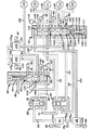
【図1】本発明のパワー変速機シフト制御装置の概略構成図である。
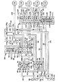
【図2】図1と同様の図であるが、後進流制御弁を圧力設定位置に設定するために禁止ソレノイド弁が開いている状態を示す図である。
【図3】図1の一部の拡大断面図である。
【図4】図3と同様の図であるが、変速機の第2駆動比を実行する弁状態を示す図である。
【図5】図3、4と同様の図であるが、変速機の第3駆動比を実行する弁状態を示す図である。
【図6】図3ないし図5と同様の図であるが、変速機の第4駆動比を実行する弁状態を示す図である。
【図7】図3ないし図6と同様の図であるが、変速機の第5駆動比を実行する弁状態を示す図である。
【図8】図7と同様の図であるが、電気エネルギの損失が生じた後に変速機の第5駆動比を実行する弁状態を示す図である。
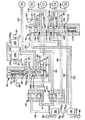
【図9】図1、2と同様の図であるが、変速機の後進駆動レンジを実行するシフトフォークコントローラの状態を示す図である。
【図10】図8と同様の拡大図であるが、制御弁機構を一層詳細に示す図である。
【図11】前進駆動レンジ及び後進駆動レンジにおけるソレノイド弁や変調ソレノイド弁の液圧状態、及び圧力センサの状態を示す論理テーブルである。
【符号の説明】
10 制御弁機構
12 ポンプ
18 手動レンジセレクタ弁
19 シフトフォークコントローラ
20 前進流制御弁
21 後進流制御弁
22 オン/オフ禁止ソレノイド弁
23 駆動プラグ
25、26、28 オン/オフソレノイド制御弁
29 送り通路
38 制御導管
60、85 2位置スプール弁
63、112 スプール部材
64A−64D ランド部
65A−65C 室
66 制御室
69 バネ部材
87 信号制御室
88 圧力センサ
90 帰還装置
100、105 変調ソレノイド弁
113A−113F ランド部
115A−115E 室
116 制御室
119 バネ
151 送り通路
165 ハウジング
168 スプール部材
171 制御室
173 圧縮バネ[0001]
[Industrial application fields]
The present invention relates to a hydraulic shift control device for a transmission. In particular, the invention relates to a hydraulic control device that is particularly suitable for operating a torque transmission device in order to establish the respective drive ratio in a countershaft type automatic transmission.
[0002]
[Prior art and its problems]
It is well known to use hydraulic pistons to control the position of the synchronizer sleeve. A typical device of this type is disclosed in US Pat. No. 5,233,878. The device has a double acting piston that is pressurized to move the shift fork to a predetermined operating position. The shift fork is operatively connected to a synchronizer, and the synchronizer cooperates with a fluid actuated torque transmitting friction device (clutch or brake) to establish two separate power paths in a countershaft type transmission (e.g., US (See Japanese Patent No. 5,009,116). In the above two US patent specifications, a hydraulically actuated shift fork controls the positioning of the forward / reverse synchronizer. When the synchronizer is positioned, a power path in the transmission is established by activating the appropriate fluid-actuated torque transmission device.
[0003]
Traditionally, a number of mechanical, hydraulic and / or electrical devices that actuate several torque transmission devices used in the transmission to implement the drive or gear ratio provided by the power transmission. Equipment has been developed.
[0004]
[Configuration and effect of the invention]
The hydraulic shift control device according to the present invention is characterized by a fluid pressure source; a first two-position spool valve means; a control chamber provided in the first spool valve means; and connected to the fluid pressure source. First on / off solenoid control valve means; from the first on / off solenoid control valve means to generate a pressure setting state when the first on / off solenoid control valve means is on. First control conduit means for directing fluid to the control chamber of the spool valve means; and biasing the first spool valve means to cause a spring set condition when the first on / off solenoid control valve means is off. A second spring valve means; a second two-position spool valve means; a control chamber provided in the second spool valve means; a second on / off solenoid control valve means connected to a fluid pressure source; 2 on / off so A second for directing fluid from the second on / off solenoid control valve means to the control chamber of the second spool valve means to cause the second spool valve means to create a pressure setting condition when the noid control valve means is on. Two control conduit means; and spring means for biasing the second spool valve means to cause a spring setting condition in the second spool valve means when the second on / off solenoid control valve means is in the off state; A first modulation solenoid valve means connected to the fluid source and the first spool valve means for directing fluid flow to the selected torque transmission device; to direct fluid flow to the other selected torque transmission device; A second modulation solenoid valve means connected to the fluid source and the second spool valve means.
[0005]
Further, the forward / reverse shift control mechanism according to the present invention is characterized in that a fluid operated forward / reverse shift controller means connected to a fluid pressure source; and a plurality of operating states connected to the fluid pressure source are selected. Manual shift valve means; and first flow control valve means for directing fluid from the manual shift valve means to the shift controller means for performing the first position when the manual shift valve means is in the forward drive state; Second flow control valve means for directing fluid from the manual shift valve means to the shift controller means for performing the second position when the valve means is in the reverse drive state.
[0006]
The present invention relates to a shift control device and mechanism of a simple structure which is particularly suitable for operating a twin countershaft type automatic transmission which provides five drive ratios.
[0007]
A control valve mechanism for a transmission embodying the present invention uses a fluid pressure source. The first two-position spool valve means has a control chamber connected to a fluid pressure source. In particular, when the first on / off solenoid valve means is in the on state (hydraulic communication state), the control conduit passes from the first on / off solenoid valve means to the first spool via the first two-position shuttle valve. The pressurized hydraulic fluid is guided to the control chamber of the valve means, and the spool valve member of the spool valve means is positioned at the pressure setting position. When the first on / off solenoid valve means is in the off state (hydraulic communication blocking state), the spring means positions the spool valve member of the spool valve means at the spring setting position.
[0008]
The second two-position spool valve means has a control chamber connected to a fluid pressure source via second on / off solenoid valve means. When the second on / off solenoid valve means is in the on state (hydraulic communication state), the control passage guides pressurized hydraulic fluid from the second on / off solenoid valve means to the control chamber of the second spool valve means, The spool valve member of the spool valve means is positioned at the pressure setting position. When the second on / off solenoid valve means is in the off state (hydraulic communication blocking state), the spring means positions the spool valve member of the second spool valve means at the spring setting position.
[0009]
The plurality of torque transmitting friction devices perform the same number of drive ratios or gear ratios. The first modulating solenoid valve means selectively directs pressurized hydraulic fluid to the selected torque transmitting friction device via the first spool valve means. The second modulating solenoid valve means selectively directs pressurized hydraulic fluid to the other selected torque transmitting friction device via the second spool valve means.
[0010]
【Example】
The hydraulic
[0011]
The present invention is particularly suitable for use in combination with a shift fork control mechanism 11 (FIG. 1) of a transmission.
[0012]
The shift
[0013]
The
[0014]
The lateral feed conduit 16A1 is connected to a normally closed on / off inhibition
[0015]
When the manual
[0016]
When the manual
[0017]
The tip of the
[0018]
Continuing the description of the first two-
[0019]
The
[0020]
The second two-
[0021]
The
[0022]
The first two-
[0023]
The
[0024]
[0025]
The
[0026]
A
[0027]
The first three-way
[0028]
With further reference to the first two-
[0029]
The second two-
[0030]
Due to the action of the
[0031]
The
[0032]
The
[0033]
The
[0034]
The shut-off
[0035]
The first / fifth drive
[0036]
The second normally closed on / off
[0037]
The second three-way
[0038]
Before describing the operation of the
[0039]
The flow described above is achieved when the
[0040]
When each on / off
[0041]
In order to make the drawing easier to see, the pressurized conduits and passages are shown in a knitted pattern (fine dot pattern).
[0042]
A full understanding of the interaction between the forward / reverse normally off on / off inhibit
[0043]
The reverse
[0044]
The control plug 23 is positioned in axial alignment with the
[0045]
When the normally closed on / off prohibiting
[0046]
When pressurized fluid is present in the
[0047]
As will be described in detail later, the inhibit
[0048]
As a result, when the driver moves the manual
[0049]
At the neutral position N of the manual
[0050]
In general, automobile transmissions have gear elements that can be selectively engaged to provide multiple forward speeds or drive ratios, and engine output torque is supplied to the drive wheels of the automobile through these gear elements. Is done. In automatic transmissions, gear elements providing various drive ratios are selectively actuated via fluid actuated torque transmitting friction devices such as clutches and brakes. Therefore, in order to shift from one drive ratio to another, the torque transmission device related to the current drive ratio is released (disengaged), and the torque transmission device related to the drive ratio to be shifted from now on Is applied (engaged). A torque transmission device to be released during a specific shift is called an “off-going torque transmission device”, and a torque transmission device to be engaged during the same shift is called an “oncoming torque transmission device”. In addition, there is a slight overlap between the “disengagement” and “engagement” of the associated torque transmission device during the shift, and a good quality shift will ensure proper “disengagement” and “engagement” operation It can be obtained only when it is executed at a certain timing.
[0051]
Conventionally, shift control performed by an automatic transmission is performed in relation to a logical control map and various inputs that reflect system parameters such as vehicle speed, engine throttle position, and engine torque. Fluid pressure signals representing various system parameters are processed by an on-board computer and / or microprocessor to properly shift according to the control logic map and to control the hydraulic controller in response to signals received from the computer. Whether or not the required engagement and / or disengagement of the torque transmission required to properly operate the valve and ensure the desired drive ratio change to the transmission output shaft is (proper) To decide.
[0052]
Operation of the first drive ratio
The first drive ratio, i.e., the first gear ratio, is increased in the first and second
[0053]
At the same time, the flow of hydraulic fluid at a substantial line pressure passes through the second normally closed on / off solenoid
[0054]
In the pressure setting position of the
[0055]
When both the first and
[0056]
When only the first three-way
[0057]
When the above shift to the first drive ratio is complete, the onboard computer and / or the microprocessor should begin preparing for the shift from the first drive ratio to the second drive ratio (part of the preliminary shift logic). Only after a call is made, the forbidden solenoid valve switches to the on state as shown in FIG. When the prohibit
[0058]
Operation of the second drive ratio
The second drive ratio is established when the
[0059]
When the three-way
[0060]
When the second three-way
[0061]
The line pressure for operating the torque transmitting friction device C2 by opening the second
[0062]
When the above shift to the first drive ratio is complete, the onboard computer and / or the microprocessor should begin preparing for the shift from the second drive ratio to the third drive ratio (part of the preliminary shift logic). Only after the transmission is made, the
[0063]
When the
[0064]
When the
[0065]
Therefore, before the shift to the third drive ratio is completed, the
[0066]
The preparation for shifting from the second drive ratio to the third drive ratio will be described in detail. The off-going pressure from the torque transmission friction device C1 is drained through the
[0067]
What is required in advance for the shift to the third drive ratio is that the prohibit
[0068]
3rd drive ratio operation
The third drive ratio is established when the
[0069]
When the second
[0070]
When the first
[0071]
The line pressure for operating the torque transmitting friction device C3 by opening the first
[0072]
When the above shift to the third drive ratio is complete, the onboard computer and / or the microprocessor should begin preparing for the shift from the third drive ratio to the fourth drive ratio (part of the preliminary shift logic). Only after transmission, the second on / off shift
[0073]
When the
[0074]
When both shift
[0075]
Again, the
[0076]
4th drive ratio operation
The fourth drive ratio is established when the
[0077]
When the first
[0078]
The line pressure for operating the torque transmitting friction device C4 by opening the second
[0079]
To prevent undesired shift combinations (eg, a shift from the fourth drive ratio to the second drive ratio when a suitable synchronizer is mounted on the same shaft), prevent such shifts from occurring Means are provided. For this purpose, as shown in FIG. 6, the
[0080]
When the above shift to the fourth drive ratio is complete, the onboard computer and / or the microprocessor should begin preparing for the shift from the fourth drive ratio to the fifth drive ratio (part of the preliminary shift logic). Only after transmission, the first on / off shift
[0081]
When the
[0082]
The
[0083]
5th drive ratio operation
The fifth drive ratio is established when the
[0084]
When the second
[0085]
When the first
[0086]
As shown in FIG. 7, the pressurized hydraulic fluid from the first on / off solenoid
[0087]
In addition, pressurized hydraulic fluid flows from
[0088]
The hydraulic fluid continues to pressurize the spring assist
[0089]
Operation under loss of electrical energy
The on / off
[0090]
The
[0091]
Referring to FIG. 3, the first on / off
[0092]
When the
[0093]
Referring to FIG. 4, if a loss of electrical power occurs while operating at the second drive ratio, the second on / off
[0094]
With further reference to FIG. 4, when the
[0095]
The loss of electrical energy for the on / off
[0096]
In operation at the third drive ratio, energization of the solenoid valve is not necessary. Accordingly, even if electric energy is lost during operation at the third drive ratio, the operation of the transmission is not changed.
[0097]
Referring to FIG. 6, if electrical energy is lost while operating at the fourth drive ratio, the first on / off
[0098]
With further reference to FIG. 6, when the first on / off
[0099]
Conversely, when a loss of electric power occurs during the fifth drive ratio (FIG. 7), the first on / off
[0100]
In particular, the pressurized fluid supplied to the
[0101]
Since the
[0102]
Reverse drive range operation
The hydraulic fluid obtained by positioning the manual
[0103]
In the state shown in FIG. 9, the hydraulic fluid passing through the
[0104]
9 and 10, when the manual
[0105]
When electric power is lost during operation of the reverse drive range, the
[0106]
Obviously, various modifications and variations can be made to the techniques described above. For example,
[0107]
In addition, the
[0108]
In the present invention, the automatic transmission can conveniently supply the working fluid to the torque transmission device to achieve the required purpose. From the above description of the forward drive ratio, it can be seen that different torque transmitting friction devices are required to achieve each drive ratio. Also, it can be seen from the above description that the shift between the forward drive ratios is achieved by disengaging one torque transmitting friction device and engaging another torque transmitting friction device substantially simultaneously. This is accomplished by a unique controller that uses two spool valves in combination with two modulating solenoid valves and uses two on / off solenoid valves that operate in conjunction with a pair of two position shuttle valves. .
[0109]
In conclusion, in the present invention, the improved transmission control valve mechanism can perform a selective shift of an automatic transmission of the five forward counter twin countershaft type, which uses only two modulation valves. Thus, it is achieved by controlling the oncoming fluid pressure and the offgoing fluid pressure involved in the operation and inactivation of the torque transmission device that shifts between the drive ratios of the transmission.
[Brief description of the drawings]
FIG. 1 is a schematic configuration diagram of a power transmission shift control device of the present invention.
FIG. 2 is a view similar to FIG. 1, but showing a state in which the prohibition solenoid valve is open to set the reverse flow control valve to the pressure setting position.
FIG. 3 is an enlarged cross-sectional view of a part of FIG.
4 is a view similar to FIG. 3, but showing a valve state in which the second drive ratio of the transmission is executed. FIG.
FIG. 5 is a view similar to FIGS. 3 and 4, but showing a valve state in which a third drive ratio of the transmission is executed.
FIG. 6 is a view similar to FIGS. 3 to 5, but showing a valve state in which a fourth drive ratio of the transmission is executed.
FIG. 7 is a view similar to FIGS. 3 to 6, but illustrating a valve state in which a fifth drive ratio of the transmission is executed.
FIG. 8 is a view similar to FIG. 7, but showing a valve state in which the fifth drive ratio of the transmission is executed after loss of electrical energy has occurred.
FIG. 9 is a view similar to FIGS. 1 and 2, but showing a state of the shift fork controller that executes the reverse drive range of the transmission.
FIG. 10 is an enlarged view similar to FIG. 8, but showing the control valve mechanism in more detail.
FIG. 11 is a logical table showing a hydraulic pressure state of a solenoid valve or a modulation solenoid valve and a state of a pressure sensor in a forward drive range and a reverse drive range.
[Explanation of symbols]
10 Control valve mechanism
12 Pump
18 Manual range selector valve
19 Shift fork controller
20 Forward flow control valve
21 Reverse flow control valve
22 On / off prohibited solenoid valve
23 Drive plug
25, 26, 28 On / off solenoid control valve
29 Feed passage
38 Control conduit
60, 85 2-position spool valve
63, 112 Spool member
64A-64D Land part
65A-65C room
66 Control room
69 Spring member
87 Signal control room
88 Pressure sensor
90 Return device
100, 105 Modulation solenoid valve
113A-113F Land part
115A-115E room
116 Control room
119 Spring
151 Feed passage
165 housing
168 Spool member
171 Control room
173 Compression spring
Claims (11)
流体圧力源(12)と;
第1の2位置スプール弁手段(60)と;
この第1スプール弁手段に設けた制御室(66)と;
上記流体圧力源に接続された第1のオン/オフソレノイド制御弁手段(25)と;
上記第1オン/オフソレノイド制御弁手段がオン状態のときに圧力設定状態を生じさせるために当該第1オン/オフソレノイド制御弁手段から上記第1スプール弁手段の制御室へ流体を導くための第1制御導管手段(29、38)と;
上記第1オン/オフソレノイド制御弁手段がオフ状態のときにバネ設定状態を生じさせるために上記第1スプール弁手段を偏倚するためのバネ手段(69)と;
第2の2位置スプール弁手段(85)と;
この第2スプール弁手段に設けた制御室(116)と;
上記流体圧力源に接続された第2のオン/オフソレノイド制御弁手段(26)と;
上記第2オン/オフソレノイド制御弁手段がオン状態のときに上記第2スプール弁手段に圧力設定状態を生じさせるために当該第2オン/オフソレノイド制御弁手段から当該第2スプール弁手段の制御室へ流体を導くための第2制御導管手段(151)と;
上記第2オン/オフソレノイド制御弁手段がオフ状態のときに上記第2スプール弁手段にバネ設定状態を生じさせるために当該第2スプール弁手段を偏倚するためのバネ手段(119)と;
選択された上記トルク伝達装置へ流体の流れを導くため、上記流体源及び上記第1スプール弁手段に接続された第1の変調ソレノイド弁手段(100)と;
選択された他のトルク伝達装置へ流体の流れを導くため、上記流体源及び上記第2スプール弁手段に接続された第2の変調ソレノイド弁手段(105)と;
を有することを特徴とする液圧シフト制御装置。In a hydraulic pressure shift control device for an automatic transmission having a plurality of torque transmission devices (C1-C5) each executing a selected drive ratio,
A fluid pressure source (12);
First two-position spool valve means (60);
A control chamber (66) provided in the first spool valve means;
First on / off solenoid control valve means (25) connected to the fluid pressure source;
For directing fluid from the first on / off solenoid control valve means to the control chamber of the first spool valve means to produce a pressure setting state when the first on / off solenoid control valve means is on. First control conduit means (29, 38);
Spring means (69) for biasing the first spool valve means to produce a spring set condition when the first on / off solenoid control valve means is off;
Second two-position spool valve means (85);
A control chamber (116) provided in the second spool valve means;
Second on / off solenoid control valve means (26) connected to the fluid pressure source;
Control of the second spool valve means from the second on / off solenoid control valve means to cause the second spool valve means to generate a pressure setting state when the second on / off solenoid control valve means is on. Second control conduit means (151) for directing fluid to the chamber;
Spring means (119) for biasing the second spool valve means to cause the second spool valve means to generate a spring setting state when the second on / off solenoid control valve means is in an off state;
First modulated solenoid valve means (100) connected to the fluid source and the first spool valve means for directing fluid flow to the selected torque transmission device;
Second modulated solenoid valve means (105) connected to the fluid source and the second spool valve means for directing fluid flow to another selected torque transmission device;
A hydraulic pressure shift control device comprising:
上記流体圧力源(12)に接続された流体作動前進/後進シフトコントローラ手段(19)と;
上記流体圧力源に接続され、複数の作動状態を選択する手動シフト弁手段(18)と;
上記手動シフト弁手段が前進駆動状態にあるときに、当該手動シフト弁手段から第1位置を実行する上記シフトコントローラ手段へ流体を導くための第1の流れ制御弁手段(20)と;
上記手動シフト弁手段が後進駆動状態にあるときに、当該手動シフト弁手段から第2位置を実行する上記シフトコントローラ手段へ流体を導くための第2の流れ制御弁手段(21)と;
を有することを特徴とするシフト制御機構。In the forward / reverse shift control mechanism comprising the hydraulic shift control device according to any one of claims 1 to 6,
Fluid actuated forward / reverse shift controller means (19) connected to the fluid pressure source (12);
Manual shift valve means (18) connected to the fluid pressure source for selecting a plurality of operating states;
First flow control valve means (20) for directing fluid from said manual shift valve means to said shift controller means for executing a first position when said manual shift valve means is in a forward drive state;
Second flow control valve means (21) for directing fluid from said manual shift valve means to said shift controller means for executing a second position when said manual shift valve means is in a reverse drive state;
A shift control mechanism comprising:
Applications Claiming Priority (2)
| Application Number | Priority Date | Filing Date | Title |
|---|---|---|---|
| US08/199,400 US5445043A (en) | 1994-02-22 | 1994-02-22 | Hydraulic shift control for a power transmission |
| US199400 | 1994-02-22 |
Publications (2)
| Publication Number | Publication Date |
|---|---|
| JPH07259979A JPH07259979A (en) | 1995-10-13 |
| JP3615258B2 true JP3615258B2 (en) | 2005-02-02 |
Family
ID=22737340
Family Applications (1)
| Application Number | Title | Priority Date | Filing Date |
|---|---|---|---|
| JP03387395A Expired - Fee Related JP3615258B2 (en) | 1994-02-22 | 1995-02-22 | Hydraulic pressure shift control device for transmission |
Country Status (4)
| Country | Link |
|---|---|
| US (1) | US5445043A (en) |
| EP (1) | EP0668455B1 (en) |
| JP (1) | JP3615258B2 (en) |
| DE (1) | DE69504378T2 (en) |
Families Citing this family (26)
| Publication number | Priority date | Publication date | Assignee | Title |
|---|---|---|---|---|
| US5616093A (en) * | 1995-10-13 | 1997-04-01 | General Motors Corporation | Electro-hydraulic control system in a power transmission |
| US5601506A (en) * | 1995-10-13 | 1997-02-11 | General Motors Corporation | Electro-hydraulic control system in a power transmission |
| DE19546631A1 (en) * | 1995-12-14 | 1997-06-19 | Zahnradfabrik Friedrichshafen | Transmission control, in particular for an electrically shifted automatic transmission in countershaft design |
| DE19601618A1 (en) * | 1996-01-18 | 1997-07-24 | Zahnradfabrik Friedrichshafen | Safety system for an automatic transmission |
| JP2840937B2 (en) * | 1996-02-20 | 1998-12-24 | 本田技研工業株式会社 | Control device for hydraulically operated transmission |
| US5682791A (en) * | 1996-06-28 | 1997-11-04 | Caterpillar Inc. | Independent latching system for a transmission |
| JP4253899B2 (en) * | 1999-02-24 | 2009-04-15 | アイシン・エィ・ダブリュ株式会社 | Hydraulic control device for automatic transmission |
| JP3461304B2 (en) * | 1999-03-30 | 2003-10-27 | 本田技研工業株式会社 | Control device for automatic transmission |
| JP3523523B2 (en) * | 1999-04-27 | 2004-04-26 | 本田技研工業株式会社 | Control device for automatic transmission |
| JP3507729B2 (en) * | 1999-06-10 | 2004-03-15 | 本田技研工業株式会社 | Control device for automatic transmission |
| JP3461306B2 (en) * | 1999-07-22 | 2003-10-27 | 本田技研工業株式会社 | Control device for automatic transmission |
| FR2801360B1 (en) * | 1999-11-19 | 2002-04-05 | Renault | METHOD AND DEVICE FOR DRIVING AN AUTOMATIC TRANSMISSION FOR PROVIDING AN ADDITIONAL REPORT |
| DE10032680C1 (en) * | 2000-07-05 | 2001-10-25 | Daimler Chrysler Ag | Automobile automatic gearbox has control slider of gear selection control device blocked in control position upon failure of associated switching valve |
| EP1251300A3 (en) * | 2001-04-16 | 2007-11-14 | Fuji Jukogyo Kabushiki Kaisha | Hydraulic control system of automated manual transmission |
| JP2002372144A (en) * | 2001-06-15 | 2002-12-26 | Fuji Heavy Ind Ltd | Hydraulic controller for automatic transmission |
| US6898992B2 (en) * | 2003-08-08 | 2005-05-31 | Borgwarner, Inc. | Method for controlling the engagement force of the synchronizers of a dual clutch transmission |
| US8387476B2 (en) * | 2007-03-02 | 2013-03-05 | Borgwarner Inc. | Hydraulic actuation valve arrangement for dual clutch transmission |
| US8443956B2 (en) * | 2008-03-04 | 2013-05-21 | Borgwarner Inc. | Dual clutch transmission having area controlled clutch cooling circuit |
| CN101828055B (en) * | 2008-04-18 | 2013-09-04 | 博格华纳公司 | Dual clutch transmission having simplified controls |
| US8439804B2 (en) * | 2008-10-28 | 2013-05-14 | Allison Transmission, Inc. | Electro-hydraulic control including blocking features for multi-speed automatic transmission |
| US8376906B2 (en) * | 2008-12-09 | 2013-02-19 | Borgwarner Inc. | Automatic transmission for a hybrid vehicle |
| US8210976B2 (en) * | 2009-06-25 | 2012-07-03 | GM Global Technology Operations LLC | Control system for an automatic transmission having multiple default modes |
| CN102459965B (en) | 2009-06-29 | 2014-11-05 | 博格华纳公司 | Hydraulic valve for use in a control module of an automatic transmission |
| WO2011082095A2 (en) | 2009-12-31 | 2011-07-07 | Borgwarner Inc. | Automatic transmission having high pressure actuation and low pressure lube hydraulic circuit |
| WO2018118128A1 (en) * | 2016-12-22 | 2018-06-28 | Eaton Corporation | High efficiency, high output transmission |
| IT202200003086A1 (en) * | 2022-02-18 | 2023-08-18 | Marelli Europe Spa | HYDRAULIC CIRCUIT FOR A SERVO-ASSISTED MECHANICAL TRANSMISSION AND METHOD OF CONTROLING A HYDRAULIC CIRCUIT FOR A SERVO-ASSISTED MECHANICAL TRANSMISSION EQUIPPED WITH A SERVO-ASSISTED MECHANICAL GEARBOX |
Family Cites Families (7)
| Publication number | Priority date | Publication date | Assignee | Title |
|---|---|---|---|---|
| DE2945315A1 (en) * | 1979-11-09 | 1981-05-21 | Robert Bosch Gmbh, 7000 Stuttgart | HYDRAULIC CONTROL DEVICE FOR POWERTRAIN TRANSMISSION |
| US4442727A (en) * | 1980-10-29 | 1984-04-17 | Alastair John Young | Control means for rotary power transmission |
| US4838126A (en) * | 1987-11-25 | 1989-06-13 | Btr Engineering (Australia) Limited | Electro/hydraulic control system for an automatic transmission |
| US5009116A (en) * | 1990-03-30 | 1991-04-23 | General Motors Corporation | Power transmission |
| DE4117736C1 (en) * | 1991-05-30 | 1992-05-21 | Mercedes-Benz Aktiengesellschaft, 7000 Stuttgart, De | |
| JP2673613B2 (en) * | 1991-07-31 | 1997-11-05 | 本田技研工業株式会社 | Control device for automatic transmission for vehicles |
| US5233878A (en) * | 1992-06-01 | 1993-08-10 | General Motors Corporation | Closed loop control for transmission shift fork position |
-
1994
- 1994-02-22 US US08/199,400 patent/US5445043A/en not_active Expired - Fee Related
-
1995
- 1995-01-19 EP EP95200126A patent/EP0668455B1/en not_active Expired - Lifetime
- 1995-01-19 DE DE69504378T patent/DE69504378T2/en not_active Expired - Fee Related
- 1995-02-22 JP JP03387395A patent/JP3615258B2/en not_active Expired - Fee Related
Also Published As
| Publication number | Publication date |
|---|---|
| US5445043A (en) | 1995-08-29 |
| EP0668455A1 (en) | 1995-08-23 |
| DE69504378T2 (en) | 1999-01-21 |
| JPH07259979A (en) | 1995-10-13 |
| EP0668455B1 (en) | 1998-09-02 |
| DE69504378D1 (en) | 1998-10-08 |
Similar Documents
| Publication | Publication Date | Title |
|---|---|---|
| JP3615258B2 (en) | Hydraulic pressure shift control device for transmission | |
| JP2925505B2 (en) | Electrohydraulic pressure control device for power transmission | |
| JPH09126305A (en) | Power transmission controller | |
| EP0691487B1 (en) | Electronic and hydraulic control system of a 4-speed automatic transmission for automotive vehicle | |
| KR0168298B1 (en) | Hydraulic control system of automatic transmission for a vehicle | |
| US6319164B1 (en) | Electro-hydraulic control with a manual selection valve | |
| JPH08145163A (en) | Hydraulic control device for composite clutch type automatic transmission | |
| JPH09166204A (en) | Transmission controller | |
| JPH1054456A (en) | Hydraulic controller for automatic transmission | |
| JP3110004B2 (en) | Hydraulic pressure control system for vehicle automatic transmission | |
| JP4221938B2 (en) | Automatic transmission control device | |
| KR960040762A (en) | Hydraulic control system of automatic transmission for vehicles | |
| KR100288208B1 (en) | Hydraulic control system of automatic transmission for vehicle | |
| KR100288213B1 (en) | Hydraulic Control System of Automotive Transmission | |
| KR100302748B1 (en) | Hydraulic control system for automatic transmission | |
| KR100452266B1 (en) | Hydraulic system of automatic transmission for vehicles | |
| KR100309008B1 (en) | Hydraulic control system of automatic transmission for vehicle | |
| KR0180423B1 (en) | Hydraulic control system of a/t | |
| KR200213492Y1 (en) | Stopper for shift control valve for automatic transmission | |
| JP4085258B2 (en) | Automatic transmission control device | |
| JP3630253B2 (en) | Hydraulic control circuit for automatic transmission | |
| KR100279423B1 (en) | Manual valve for vehicle automatic transmission hydraulic control system | |
| KR960040763A (en) | Hydraulic control system of automatic transmission for vehicles | |
| KR100380491B1 (en) | shift control method for automatic transmission from normal range to driving range | |
| KR0180421B1 (en) | Hydraulic control system of auto-transmission |
Legal Events
| Date | Code | Title | Description |
|---|---|---|---|
| A977 | Report on retrieval |
Free format text: JAPANESE INTERMEDIATE CODE: A971007 Effective date: 20040924 |
|
| TRDD | Decision of grant or rejection written | ||
| A01 | Written decision to grant a patent or to grant a registration (utility model) |
Free format text: JAPANESE INTERMEDIATE CODE: A01 Effective date: 20041001 |
|
| A61 | First payment of annual fees (during grant procedure) |
Free format text: JAPANESE INTERMEDIATE CODE: A61 Effective date: 20041029 |
|
| R150 | Certificate of patent or registration of utility model |
Free format text: JAPANESE INTERMEDIATE CODE: R150 |
|
| LAPS | Cancellation because of no payment of annual fees |