EP0664650A1 - Decodeur et procede de decodage - Google Patents
Decodeur et procede de decodage Download PDFInfo
- Publication number
- EP0664650A1 EP0664650A1 EP94919894A EP94919894A EP0664650A1 EP 0664650 A1 EP0664650 A1 EP 0664650A1 EP 94919894 A EP94919894 A EP 94919894A EP 94919894 A EP94919894 A EP 94919894A EP 0664650 A1 EP0664650 A1 EP 0664650A1
- Authority
- EP
- European Patent Office
- Prior art keywords
- decoding
- predetermined system
- coded signal
- picture
- conformity
- Prior art date
- Legal status (The legal status is an assumption and is not a legal conclusion. Google has not performed a legal analysis and makes no representation as to the accuracy of the status listed.)
- Granted
Links
Images


Classifications
-
- H—ELECTRICITY
- H04—ELECTRIC COMMUNICATION TECHNIQUE
- H04N—PICTORIAL COMMUNICATION, e.g. TELEVISION
- H04N5/00—Details of television systems
- H04N5/76—Television signal recording
- H04N5/84—Television signal recording using optical recording
- H04N5/85—Television signal recording using optical recording on discs or drums
-
- H—ELECTRICITY
- H04—ELECTRIC COMMUNICATION TECHNIQUE
- H04N—PICTORIAL COMMUNICATION, e.g. TELEVISION
- H04N5/00—Details of television systems
- H04N5/76—Television signal recording
- H04N5/91—Television signal processing therefor
- H04N5/93—Regeneration of the television signal or of selected parts thereof
-
- H—ELECTRICITY
- H04—ELECTRIC COMMUNICATION TECHNIQUE
- H04N—PICTORIAL COMMUNICATION, e.g. TELEVISION
- H04N19/00—Methods or arrangements for coding, decoding, compressing or decompressing digital video signals
-
- H—ELECTRICITY
- H04—ELECTRIC COMMUNICATION TECHNIQUE
- H04N—PICTORIAL COMMUNICATION, e.g. TELEVISION
- H04N19/00—Methods or arrangements for coding, decoding, compressing or decompressing digital video signals
- H04N19/10—Methods or arrangements for coding, decoding, compressing or decompressing digital video signals using adaptive coding
- H04N19/169—Methods or arrangements for coding, decoding, compressing or decompressing digital video signals using adaptive coding characterised by the coding unit, i.e. the structural portion or semantic portion of the video signal being the object or the subject of the adaptive coding
- H04N19/17—Methods or arrangements for coding, decoding, compressing or decompressing digital video signals using adaptive coding characterised by the coding unit, i.e. the structural portion or semantic portion of the video signal being the object or the subject of the adaptive coding the unit being an image region, e.g. an object
- H04N19/174—Methods or arrangements for coding, decoding, compressing or decompressing digital video signals using adaptive coding characterised by the coding unit, i.e. the structural portion or semantic portion of the video signal being the object or the subject of the adaptive coding the unit being an image region, e.g. an object the region being a slice, e.g. a line of blocks or a group of blocks
-
- H—ELECTRICITY
- H04—ELECTRIC COMMUNICATION TECHNIQUE
- H04N—PICTORIAL COMMUNICATION, e.g. TELEVISION
- H04N19/00—Methods or arrangements for coding, decoding, compressing or decompressing digital video signals
- H04N19/42—Methods or arrangements for coding, decoding, compressing or decompressing digital video signals characterised by implementation details or hardware specially adapted for video compression or decompression, e.g. dedicated software implementation
- H04N19/423—Methods or arrangements for coding, decoding, compressing or decompressing digital video signals characterised by implementation details or hardware specially adapted for video compression or decompression, e.g. dedicated software implementation characterised by memory arrangements
-
- H—ELECTRICITY
- H04—ELECTRIC COMMUNICATION TECHNIQUE
- H04N—PICTORIAL COMMUNICATION, e.g. TELEVISION
- H04N19/00—Methods or arrangements for coding, decoding, compressing or decompressing digital video signals
- H04N19/50—Methods or arrangements for coding, decoding, compressing or decompressing digital video signals using predictive coding
- H04N19/503—Methods or arrangements for coding, decoding, compressing or decompressing digital video signals using predictive coding involving temporal prediction
-
- H—ELECTRICITY
- H04—ELECTRIC COMMUNICATION TECHNIQUE
- H04N—PICTORIAL COMMUNICATION, e.g. TELEVISION
- H04N19/00—Methods or arrangements for coding, decoding, compressing or decompressing digital video signals
- H04N19/50—Methods or arrangements for coding, decoding, compressing or decompressing digital video signals using predictive coding
- H04N19/587—Methods or arrangements for coding, decoding, compressing or decompressing digital video signals using predictive coding involving temporal sub-sampling or interpolation, e.g. decimation or subsequent interpolation of pictures in a video sequence
-
- H—ELECTRICITY
- H04—ELECTRIC COMMUNICATION TECHNIQUE
- H04N—PICTORIAL COMMUNICATION, e.g. TELEVISION
- H04N19/00—Methods or arrangements for coding, decoding, compressing or decompressing digital video signals
- H04N19/60—Methods or arrangements for coding, decoding, compressing or decompressing digital video signals using transform coding
- H04N19/61—Methods or arrangements for coding, decoding, compressing or decompressing digital video signals using transform coding in combination with predictive coding
-
- H—ELECTRICITY
- H04—ELECTRIC COMMUNICATION TECHNIQUE
- H04N—PICTORIAL COMMUNICATION, e.g. TELEVISION
- H04N19/00—Methods or arrangements for coding, decoding, compressing or decompressing digital video signals
- H04N19/90—Methods or arrangements for coding, decoding, compressing or decompressing digital video signals using coding techniques not provided for in groups H04N19/10-H04N19/85, e.g. fractals
-
- H—ELECTRICITY
- H04—ELECTRIC COMMUNICATION TECHNIQUE
- H04N—PICTORIAL COMMUNICATION, e.g. TELEVISION
- H04N5/00—Details of television systems
- H04N5/76—Television signal recording
- H04N5/78—Television signal recording using magnetic recording
- H04N5/782—Television signal recording using magnetic recording on tape
- H04N5/783—Adaptations for reproducing at a rate different from the recording rate
-
- H—ELECTRICITY
- H04—ELECTRIC COMMUNICATION TECHNIQUE
- H04N—PICTORIAL COMMUNICATION, e.g. TELEVISION
- H04N5/00—Details of television systems
- H04N5/76—Television signal recording
- H04N5/91—Television signal processing therefor
- H04N5/92—Transformation of the television signal for recording, e.g. modulation, frequency changing; Inverse transformation for playback
- H04N5/926—Transformation of the television signal for recording, e.g. modulation, frequency changing; Inverse transformation for playback by pulse code modulation
- H04N5/9261—Transformation of the television signal for recording, e.g. modulation, frequency changing; Inverse transformation for playback by pulse code modulation involving data reduction
- H04N5/9262—Transformation of the television signal for recording, e.g. modulation, frequency changing; Inverse transformation for playback by pulse code modulation involving data reduction using predictive coding
-
- H—ELECTRICITY
- H04—ELECTRIC COMMUNICATION TECHNIQUE
- H04N—PICTORIAL COMMUNICATION, e.g. TELEVISION
- H04N5/00—Details of television systems
- H04N5/76—Television signal recording
- H04N5/91—Television signal processing therefor
- H04N5/92—Transformation of the television signal for recording, e.g. modulation, frequency changing; Inverse transformation for playback
- H04N5/926—Transformation of the television signal for recording, e.g. modulation, frequency changing; Inverse transformation for playback by pulse code modulation
- H04N5/9265—Transformation of the television signal for recording, e.g. modulation, frequency changing; Inverse transformation for playback by pulse code modulation with processing of the sound signal
- H04N5/9267—Transformation of the television signal for recording, e.g. modulation, frequency changing; Inverse transformation for playback by pulse code modulation with processing of the sound signal using time division multiplex of the PCM audio and PCM video signals
-
- H—ELECTRICITY
- H04—ELECTRIC COMMUNICATION TECHNIQUE
- H04N—PICTORIAL COMMUNICATION, e.g. TELEVISION
- H04N19/00—Methods or arrangements for coding, decoding, compressing or decompressing digital video signals
- H04N19/10—Methods or arrangements for coding, decoding, compressing or decompressing digital video signals using adaptive coding
- H04N19/102—Methods or arrangements for coding, decoding, compressing or decompressing digital video signals using adaptive coding characterised by the element, parameter or selection affected or controlled by the adaptive coding
- H04N19/103—Selection of coding mode or of prediction mode
- H04N19/107—Selection of coding mode or of prediction mode between spatial and temporal predictive coding, e.g. picture refresh
-
- H—ELECTRICITY
- H04—ELECTRIC COMMUNICATION TECHNIQUE
- H04N—PICTORIAL COMMUNICATION, e.g. TELEVISION
- H04N19/00—Methods or arrangements for coding, decoding, compressing or decompressing digital video signals
- H04N19/10—Methods or arrangements for coding, decoding, compressing or decompressing digital video signals using adaptive coding
- H04N19/102—Methods or arrangements for coding, decoding, compressing or decompressing digital video signals using adaptive coding characterised by the element, parameter or selection affected or controlled by the adaptive coding
- H04N19/13—Adaptive entropy coding, e.g. adaptive variable length coding [AVLC] or context adaptive binary arithmetic coding [CABAC]
-
- H—ELECTRICITY
- H04—ELECTRIC COMMUNICATION TECHNIQUE
- H04N—PICTORIAL COMMUNICATION, e.g. TELEVISION
- H04N19/00—Methods or arrangements for coding, decoding, compressing or decompressing digital video signals
- H04N19/60—Methods or arrangements for coding, decoding, compressing or decompressing digital video signals using transform coding
-
- H—ELECTRICITY
- H04—ELECTRIC COMMUNICATION TECHNIQUE
- H04N—PICTORIAL COMMUNICATION, e.g. TELEVISION
- H04N19/00—Methods or arrangements for coding, decoding, compressing or decompressing digital video signals
- H04N19/70—Methods or arrangements for coding, decoding, compressing or decompressing digital video signals characterised by syntax aspects related to video coding, e.g. related to compression standards
-
- H—ELECTRICITY
- H04—ELECTRIC COMMUNICATION TECHNIQUE
- H04N—PICTORIAL COMMUNICATION, e.g. TELEVISION
- H04N19/00—Methods or arrangements for coding, decoding, compressing or decompressing digital video signals
- H04N19/90—Methods or arrangements for coding, decoding, compressing or decompressing digital video signals using coding techniques not provided for in groups H04N19/10-H04N19/85, e.g. fractals
- H04N19/91—Entropy coding, e.g. variable length coding [VLC] or arithmetic coding
-
- H—ELECTRICITY
- H04—ELECTRIC COMMUNICATION TECHNIQUE
- H04N—PICTORIAL COMMUNICATION, e.g. TELEVISION
- H04N5/00—Details of television systems
- H04N5/76—Television signal recording
- H04N5/78—Television signal recording using magnetic recording
- H04N5/781—Television signal recording using magnetic recording on disks or drums
-
- H—ELECTRICITY
- H04—ELECTRIC COMMUNICATION TECHNIQUE
- H04N—PICTORIAL COMMUNICATION, e.g. TELEVISION
- H04N5/00—Details of television systems
- H04N5/76—Television signal recording
- H04N5/78—Television signal recording using magnetic recording
- H04N5/782—Television signal recording using magnetic recording on tape
- H04N5/7824—Television signal recording using magnetic recording on tape with rotating magnetic heads
- H04N5/7826—Television signal recording using magnetic recording on tape with rotating magnetic heads involving helical scanning of the magnetic tape
- H04N5/78263—Television signal recording using magnetic recording on tape with rotating magnetic heads involving helical scanning of the magnetic tape for recording on tracks inclined relative to the direction of movement of the tape
-
- H—ELECTRICITY
- H04—ELECTRIC COMMUNICATION TECHNIQUE
- H04N—PICTORIAL COMMUNICATION, e.g. TELEVISION
- H04N9/00—Details of colour television systems
- H04N9/79—Processing of colour television signals in connection with recording
- H04N9/80—Transformation of the television signal for recording, e.g. modulation, frequency changing; Inverse transformation for playback
- H04N9/804—Transformation of the television signal for recording, e.g. modulation, frequency changing; Inverse transformation for playback involving pulse code modulation of the colour picture signal components
- H04N9/8042—Transformation of the television signal for recording, e.g. modulation, frequency changing; Inverse transformation for playback involving pulse code modulation of the colour picture signal components involving data reduction
- H04N9/8045—Transformation of the television signal for recording, e.g. modulation, frequency changing; Inverse transformation for playback involving pulse code modulation of the colour picture signal components involving data reduction using predictive coding
-
- H—ELECTRICITY
- H04—ELECTRIC COMMUNICATION TECHNIQUE
- H04N—PICTORIAL COMMUNICATION, e.g. TELEVISION
- H04N9/00—Details of colour television systems
- H04N9/79—Processing of colour television signals in connection with recording
- H04N9/80—Transformation of the television signal for recording, e.g. modulation, frequency changing; Inverse transformation for playback
- H04N9/804—Transformation of the television signal for recording, e.g. modulation, frequency changing; Inverse transformation for playback involving pulse code modulation of the colour picture signal components
- H04N9/8042—Transformation of the television signal for recording, e.g. modulation, frequency changing; Inverse transformation for playback involving pulse code modulation of the colour picture signal components involving data reduction
- H04N9/8047—Transformation of the television signal for recording, e.g. modulation, frequency changing; Inverse transformation for playback involving pulse code modulation of the colour picture signal components involving data reduction using transform coding
Definitions
- This invention relates to a decoding method for moving picture signals and a decoding apparatus therefor, which are adapted to reproducing and decoding coded digital moving picture signals recorded on a recording medium such as optical disc, hard disc or magnetic tape, etc., and more particularly to high speed reproduction.
- moving picture data Since moving picture data has extremely large quantity of information, it is required for recording/reproducing such moving picture data to use recording media having extremely high continuous transmission rate (speed). Moreover, it is required for transmitting such data to use a communication path having large transmission capacity.
- VTR using magnetic tape having large tape width, or optical disc recording/reproducing apparatus using optical disc having diameter of about 30 cm is required.
- Tables shown in FIGS. 18 to 25 are tables in which syntax is defined. This syntax describes a procedure for permitting analysis of a predetermined bit stream when that bit stream is provided to restore (reconstruct) original signals.
- FIG. 18 defines video sequence, which is described by programmable language. Such video sequence can be read as flowchart.
- this syntax is described in a form such that at least men skilled in the art which study standard of MPEG can easily comprehend its technical contents.
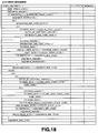
- FIG. 19 shows an example of sequence header.
- the sequence header serves to define the form of moving picture displayed, and, e.g., No. of scanning lines and aspect ratio, etc. are defined. Its example will be described below.
- horizontal_size consists of LSB of 12 bits (horizontal_size_value) and MSB of 2 bits (horizontal_size_extension of sequence_extension), and indicates displayable lateral width at luminance component of picture by 14 bits in total.
- vertical_size consists of LSB of 12 bits (vertical_size_value) and MSB of 2 bits (vertical_size_extension of sequence-extension), and indicates displayable longitudinal width at luminance component of picture by 14 bits.
- frame_rate is flag of 4 bits and the detail of the content of flag is shown in FIG. 26.
- bit_rate is represented by integer of 30 bits in total of 18 bits of LSB side indicating bit_rate in sequence header and 12 bits of MSB side indicating bit_rate_extension of sequence_extension. Integer of 30 bits indicates bit rate of bit stream with 400 bits/second being as a unit. Fraction is indicated by round-up. Zero is inhibit. Moreover, in the case of variable rate, "3FFFFFFF" is designated.
- vbv_buffer_size is flag of 10 bits and indicates LSB side 10 bits of vbv_buffer_size.
- VBV buffer size is represented by integer of 18 bits. 10 bits of LSB (Least Significant Bit) side is vbv_buffer_size, and 8 bits of MSB side is represented by vbv_buffer_size_extension in sequence_extension. This integer of 18 bits indicates VBV buffer size necessary for decoding sequence.
- VBV is virtually buffer control system for allowing buffer that decoder has not to overflow or underflow, and the detail thereof is described in MPEG 2 Working Draft or Annex C of Test Model.
- B 16 * 1024 * vbv_buffer_size B indicates VBV buffer size necessary as minimum as possible for decoding sequence in terms of bit units.
- FIG. 20 shows an example of table of quantization matrix.
- load_intra_quantizer_matrix is flag of 1 bit. In the case where intra_quantizer_matrix is down-loaded, this bit is set to "1". In the case where that bit is set to "0", default values shown in FIG. 27 are used.
- intra_quantizer_matrix is data of 8 bits x 64. In the case where this is down-loaded, values are transmitted in order of zigzag scan, and current value is overwritten onto the previous (former) value. Down-loaded value is valid (effective) until it is down-loaded next.
- load_non_intra_quantizer_matrix is flag of 1 bit.
- non_intra_quantizer_matrix In the case where non_intra_quantizer_matrix is down-loaded, this bit is set to "1". In the case where this bit is set to "0", default values shown in FIG. 28 are used.
- non_intra_quantizer_matrix is data of 8 bits x 64. In the case where such data is down-loaded, respective values are transmitted in order of zigzag scan, and current value is overwritten onto the previous (former) value. Down-loaded value is valid (effective) until it is down-loaded next.
- chroma_format is flag of 2 bits, and can indicate three kinds of formats of color difference signals as shown by the following table. flag Meaning 00 reserved 01 4:2:0 10 4:2:2 11 4:4:4 sequence_start_code_identifier is flag of 4 bits and is identifier indicating type of extension_data. This is shown in FIG. 29.
- FIG. 21, 22 show picture header.
- temporal_reference is flag of 10 bits and indicates display order of picture. This is expressed by remainder when value incrementing by one every time picture is inputted at counter of picture is divided by 1024. In respective GOPs, temporal_reference is reset to 0 by the first picture in terms of display order of picture. Moreover, in the case where frame is divided into two fields by Field coding, temporal_reference with respect two fields are the same value.
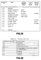
- picture_coding_type is flag of 3 bits and is identifier of picture coding type, and there are Intra-frame coded picture (I picture), Predictive (coded) picture (P picture), Bidirectionally predictive (coded) picture (B picture) and only DC component of intra-frame coded picture (D picture). They are shown in FIG.
- vbv_delay is flag of 16 bits. In the case of fixed rate coding, vbv_delay is used for setting initial value of buffer occupation ratio in the case of start of decode of decoder. By this flag, it is possible to avoid overflow or underflow of decoder buffer. vbv_delay is designated by delay time required until VBV buffer is caused to be from empty state to the state having correct buffer occupation ratio at target bit rate R. Thereafter, the first picture data is taken out from VBV buffer.
- intra_dc_precision is indicated by the following table. flag Meaning 00 dc_precision : 8 bits 01 dc_precision : 9 bits 10 dc_precision : 10 bits 11 dc_precision : 11 bits picture_structure is flag of 2 bits and is identifier for carrying out switching between Frame structure and Field structure.
- VLC alternate_scan is flag of 1 bit. In the case where this flag is set to "0”, ordinary zigzag scan is used. In the case where this flag is set to "1”, zigzag scan of different path is used.
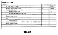
- slice_start_code is start code of 32 bits, wherein the first 24 bits are "000001" in hexadecimal notation and slice_vertical_position of 8 bits is subsequent thereto.
- This slice_vertical_position takes values in the range from "01" to "AF”.
- slice_vertical_position indicates vertical position of the leading macro block within slice.
- slice_vertical_position of the first column of macro block is 1.
- slice_vertical_position must be set so that slices do not overlap and do not have gap therebetween. Maximum value of slice_vertical_position is 175.
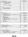
- FIG. 24 is macro block header.
- macroblock_address_increment indicates difference between address of the previous (former) macro block and address of current macro block by VLC. Maximum value of macroblock_address_increment is 33. Values more than 33 are represented by combination of macroblock_address_increment and macroblock_escape.
- Macro block address (macroblock-address) is variable (parameter) for defining absolute address of current macro block. macroblock_address becomes equal to 0 at macro block of the left upper of picture frame.
- the previous macro block address (previous_macroblock_address) is variable (parameter) for defining absolute address of macro block immediately before which is not skipped except for the leading macro block of slice.
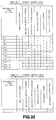
- macroblock_type is VLC code indicating type of coding method of macro block. Macro block types are shown in FIGS. 31 and 32.
- intra-frame intra-frame coded frame
- I picture intra-picture
- temporal_reference becomes discontinuous.
- corresponding picture is dealt as skip picture. Namely, frame immediately before that frame is repeatedly displayed. For this reason, high speed reproduction becomes impossible.
- a decoding method of this invention is directed to a decoding method for a coded signal encoded by a predetermined system, the method comprising the steps of receiving a coded signal consisting of a portion which is in conformity with the predetermined system and a portion which is not in conformity with the predetermined system, transforming the portion which is in conformity with the predetermined system into another signal, or supplementing insufficient information to the portion which is not in conformity with the predetermined system, transforming the coded signal into a coded signal which is in conformity with the predetermined system, and decoding the transformed coded signal in accordance with the predetermined system.
- the decoding method of this invention reproduces, by special reproduction from a recording medium on which coded signals encoded by a predetermined system are recorded, a coded signal consisting of the portion which is in conformity with the predetermined system and the portion which is not in conformity with the predetermined system .
- the predetermined system is MPEG system or MPEG 2 system.
- the portion in conformity with the predetermined system at least includes intra-coded picture signal, and the portion which is not in conformity with the predetermined system is header information.
- decoding method of this invention transforms temporal_reference in the received decoded signal, or transforms vbv_delay in the received coded signal into a value corresponding to bit quantity of the received coded signal.
- decoding method of this invention carries out inserting of sequence_start_code and sequence_end_code every predetermined coding unit in the received coded signal, processing for transforming vbv_delay in the received coded signal into a value indicating variable rate, or inserting of stuffing data into the received coded signal.
- the received coded signal is a coded signal of a unit smaller than picture unit in the predetermined system
- decoding method of this invention judges whether or not the received signal is in conformity with the predetermined system to carry out inserting of sequence_error_code into the portion which is not in conformity with the predetermined system of the received coded signal, or processing, as skip macro block, of the portion which is not in conformity with the predetermined system of the received coded signal.
- Decoding method of this invention is directed to a decoding method for a coded signal encoded by a predetermined system, the decoding method comprising the steps of receiving coded signal consisting of a portion which is in conformity with the predetermined system and a portion which is not in conformity with the predetermined system, and decoding the received coded signal in accordance with only a portion of the predetermined system.
- decoding method of this invention reproduces, by special reproduction from recording medium on which coded signals encoded by a predetermined system are recorded, a coded signal consisting of a portion which is in conformity with the predetermined system and a portion which is not in conformity with the predetermined system.
- the predetermined system is MPEG system or MPEG 2 system.
- decoding method of this invention carries out the above-mentioned decoding by disregarding VBV and temporal_reference, and outputs already decoded picture as display picture until the next picture is decoded.
- the received coded signal at least includes intra-frame coded signal of slice unit, and carries out the above-mentioned decoding in accordance with slice_vertical_position in the received coded signal to fill up slice gap by using picture outputted last as display picture.
- decoding method of this invention carries out switching between decoding in accordance with the predetermined system and decoding in accordance with only a portion of the predetermined system on the basis of flag indicating special reproduction inserted into sequence header, or adds data of picture header and/or sequence header necessary for decoding picture coded signal of slice unit to slice header to carry out the above-mentioned decoding on the basis of the added data.
- Decoding apparatus of this invention is directed to a decoding apparatus for a coded signal encoded by a predetermined system, comprising: transforming means adapted for receiving a coded signal consisting of a portion which is in conformity with the predetermined system and a portion which is not in conformity with the predetermined system to transform the portion which is in conformity with the predetermined system into another signal, or supplementing insufficient information to the portion which is not in conformity with the predetermined system to transform the coded signal into coded signal which is in conformity with the predetermined system, and decoding means for decoding the transformed coded signal in accordance with the predetermined system.
- decoding apparatus of this invention includes reproducing means for reproducing, by special reproduction from recording medium on which coded signals encoded by a predetermined system are recorded, coded signal consisting of a portion which is in conformity with the predetermined system and a portion which is not in conformity with the predetermined system.
- the predetermined system is MPEG system or MPEG 2.
- the portion which is in conformity with the predetermined system at least includes intra-coded picture signal, and the portion which is not in conformity with the predetermined system is header information.
- decoding apparatus of this invention includes transforming means for transforming temporal_reference in the received coded signal.
- decoding apparatus of this invention includes transforming means for transforming vbv_delay in the received coded signal into a value corresponding to bit quantity of the received coded signal, inserting means for inserting sequence_start_code and sequence_end_code every predetermined coding unit in the received coded signal, and transforming means for transforming vbv_delay in the received coded signal into a value indicating variable rate, etc., and further includes inserting means for inserting stuffing data into the received coded signal.
- the received coded signal is a coded signal of unit smaller than picture unit in the predetermined system
- the decoding apparatus comprises judging means for judging whether or not the received signal is in conformity with the predetermined system, and inserting means for inserting sequence_error_code into the portion which is not in conformity with the predetermined system of the received coded signal, or judging means for judging whether or not the received signal is in conformity with the predetermined system, and the decoding means process, as skip macro block, the portion which is not in conformity with the predetermined system of the received coded signal.
- Decoding apparatus of this invention is directed to a decoding apparatus for coded signal encoded by a predetermined system, and includes decoding means adapted for receiving coded signal consisting of portion which is in conformity with the predetermined system and portion which is not in conformity with the predetermined system to decode the received coded signal in accordance with only a portion of the predetermined system.
- decoding apparatus of this invention includes reproducing means for reproducing, by special reproduction from recording medium on which coded signals encoded by a predetermined system are recorded, coded signal consisting of portion which is in conformity with the predetermined system and portion which is not in conformity with the predetermined system.
- the decoding means carries out the above-mentioned decoding by disregarding VBV and temporal_reference, and outputting of already decoded picture as display picture until the next picture is decoded.
- the received coded signal at least includes picture coded signal of slice unit, and the decoding means carries out the above-mentioned decoding in accordance with slice_vertical_position in the received coded signal, and the decoding means fills up slice gap by using picture outputted last as display picture.
- decoding means of decoding apparatus of this invention carries out switching between decoding in accordance with the predetermined system and decoding in accordance with a portion of the predetermined system on the basis of flag indicating special reproduction inserted into sequence header.
- decoding apparatus of this invention includes adding means for adding, to slice header, data of picture header and/or sequence header necessary for decoding picture coded signal of slice unit, and the decoding means carries out the above-mentioned decoding on the basis of the added data.
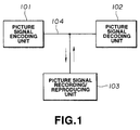
- FIG. 1 is an example of the configuration of picture signal encoding/decoding apparatuses (units) and picture signal recording apparatus (unit) to which this invention is applied.
- FIG. 2 is an example of the configuration of picture signal encoding apparatus.
- FIG. 3 is an example of the configuration of picture signal decoding apparatus.
- FIG. 4 is another example of the configuration of picture signal decoding apparatus.
- FIG. 5 is a view showing the configuration of encoding apparatus of this invention.
- FIG. 6 is a view showing the configuration of digital video disc player.
- FIG. 7 is a block diagram for explaining, in detail, recording reproducing section 604.
- FIG. 8 is a view for explaining the relationship between picture and high speed reproduction.
- FIG. 9 is a view showing the configuration of picture signal recording apparatus in first embodiment.
- FIG. 10 is a view for explaining imperfect I picture.
- FIG. 11 is a view showing, in a model form, bit stream.
- FIG. 12 is a block diagram of system configuration by first and second transition methods.
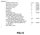
- FIG. 13 shows an example of sequence header to which ff_sequence of 1 bit is applied.
- FIG. 14 is a view showing the configuration of bit stream.
- FIG. 15 is a flowchart showing an example of slice header at the time of high speed reproduction.
- FIG. 16 is a view for explaining tracking state of video disc player.
- FIG. 17 is a view for explaining tracking state of VTR.
- FIG. 18 is a table defining video sequence.
- FIG. 19 is a table of sequence header.
- FIG. 20 is a table of quantization matrix.
- FIG. 21 is a table of picture header.
- FIG. 22 is a table of picture header.
- FIG. 23 is a table of slice header.
- FIG. 24 is a table of macro block header.
- FIG. 25 is a table of motion vector.
- FIG. 26 is a table of frame rate.
- FIG. 27 is a default value table of quantization matrix.
- FIG. 28 is a default value table of quantization matrix.
- FIG. 29 is an identifier table showing extension_data.
- FIG. 30 is an identifier table showing picture_coding_type.
- FIG. 31 is a table of VLC code showing macroblock_type.
- FIG. 32 is a table of VLC code showing macroblock_type.
- FIG. 1 Block diagram of a picture signal encoding apparatus (unit), a picture signal decoding apparatus (unit), and a picture signal recording/reproducing apparatus (unit) in the embodiment of this invention is shown in FIG. 1.
- Picture signal encoding unit 101, picture signal decoding unit 102, and picture signal recording/reproducing unit 103 are connected by way of digital signal transmission path 104.
- original picture signal is standard TV signal (NTSC, PAL, SECAM) or HDTV signal.
- Picture signal recording/reproducing apparatus (unit) 103 will now be described.
- the picture signal recording/reproducing apparatus 103 is digital VTR for recording/reproducing picture signals onto or from magnetic tape, or digital video disc for recording/reproducing picture signals onto or from optical disc, or refers to computer system for carrying out recording onto hard disc or CD-ROM.
- FIG. 5 is an example of video disc unit 500 as an example of picture signal recording/reproducing apparatus 103.
- a signal is first read by pick-up 502 to demodulate output data by means of demodulating circuit 503.
- error corrector 505 When data of one sector is stored in sector buffer 504, error correction is carried out by error corrector 505.
- the error-corrected signal is inputted to ring buffer 506.
- Drive controller 507 reads sector address of data which has been read thereinto to sent control signal to tracking servo circuit 508 in the case where track jump is required to move pick-up 502 up to a designated track to read a predetermined sector.
- Bit stream of ring buffer 506 is caused to be moving picture data by picture signal decoding apparatus (unit) 102.
- high speed reproduction in video disc unit is carried out as shown in FIG. 16 by reading out a plurality of sectors on a certain track 151 of disc 150 thereafter to carry out track jump (TJ) to read out a predetermined sector on the next predetermined track 152. At times subsequent thereto, such an operation is repeated to thereby carry out high speed reproduction of moving picture.
- high speed reproduction includes not only reproduction in time progressive direction but also reproduction in reverse direction, i.e., reverse high speed reproduction.
- VTR high speed reproduction in VTR is carried out as shown in FIG. 17. Namely, magnetic tape 160 is caused to undergo high speed feeding to thereby allow rotary head to traverse (cross) a plurality of tracks on the tape to read out a plurality of sectors on that locus. At times subsequent thereto, such an operation is repeated to thereby carry out high speed reproduction of moving picture. It should be noted that, at the time of reverse high speed reproduction, tape is caused to undergo high speed reverse (return) operation.
- the simplest high speed reproduction in the case of disc-shaped medium is a method of reproducing only data of I picture.
- decoding of picture (frame) can be made by itself.
- pick-up is moved to track including data of I picture to read out data to detect picture start code of I picture to decode data of I picture to output it.
- the disc-shaped medium even if recording is not made in the state where data for high speed reproduction is added, it is possible to read out picture header at the time of high speed reproduction.
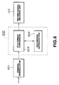
- FIG. 6 is an example of digital VTR system.
- reference numeral 601 denotes channel demodulator. Coded picture signal is inputted from input terminal to channel demodulator 601. At channel demodulator 601, transmit data is demodulated. Signal outputted from channel demodulator 601 is inputted to digital VTR 602.
- This digital VTR 602 includes interface and format converting section 603 and recording/reproducing section 604. Signal from the channel demodulator 601 is delivered to transporter through interface and format converting section 603, and is also delivered to recording/reproducing section 604.
- interface and format converting section 603 formats data sent to recording/reproducing section 604 so that reproduction picture becomes satisfactory when recording data recorded at recording/reproducing section 604 is caused to undergo high speed reproduction.
- FIG. 7 is a block diagram for explaining in detail the recording/reproducing section 604.
- Recording section of recording/reproducing section 604 comprises framing circuit 605, channel encoder 606, and rotary head 607.
- Video signal caused to have predetermined format by interface and format converting section 603 is caused to be of frame structure by framing circuit 605, and is distributed to a plurality of channels by channel encoder 606. Signals of respective channels are recorded onto magnetic tape (not shown) by means of rotary head 607.
- Reproducing section of recording/reproducing section 604 is composed of inverse framing circuit 609 and channel decoder 608, which respectively carry out operations reverse (opposite) to those of framing circuit 605 and channel encoder 606.
- Picture signal encoding apparatus 101 is constituted as shown in FIG. 2, for example.
- Input picture signal 300 is inputted to blocking circuit 301, at which it is converted from the standard format, e.g., NTSC system, etc. to block format of macro block units of, e.g., 16x16 pixels.
- the data converted into block format is inputted to motion predicting circuit 302, and is further sent to difference detector 303 therefrom.
- This difference detector 303 is supplied through predictor 317 with motion-compensated picture data from field memory groups 311 ⁇ 314 constituting frame memories 321, 322.
- the difference detector 303 detects difference between both inputs to output it.
- Output of difference detector 303 is sent to DCT circuit 304 for carrying out DCT processing which is a sort of orthogonal transform.
- DCT coefficient data obtained after undergone DCT processing at DCT circuit 304 is sent to quantizer 305, at which such data is quantized.
- Quantized data from quantizer 305 is changed into variable length code by variable length encoder 306 for carrying out variable length encoding processing such as so called Huffman coding or run length coding, etc.
- the variable length encoder 306 also encodes predictive mode, motion vector, various headers such as temporal_reference, frame_rate, vbv_delay, etc.
- code conversion system for converting fixed length code data into variable length code data is stored as table. Further, variable length coded data is outputted to digital transmission path 320 as coded data through buffer 307.
- signal corresponding to data storage quantity in buffer 307 is fed from buffer 307 back to quantizer 305 in order to prevent overflow or underflow thereof.
- Quantizer 305 is operative in correspondence with this signal so that in the case where data storage quantity attempts to overflow, it allows quantization step to be coarse to thereby decrease information quantity. On the other hand, in the case where data storage quantity attempts to underflow, the quantizer 305 allows quantization step to be fine to thereby increase information quantity.
- Quantized data outputted from quantizer 305 is inputted to inverse quantizer 308, at which inverse quantization processing complementary to quantization processing at quantizer 305 is carried out.
- Output of the inverse quantizer 308 is caused to undergo, by IDCT circuit 309, IDCT processing complementary to DCT processing at DCT circuit 304.
- Output of this IDCT circuit 309 is delivered to adder 310.
- output of IDCT circuit 309 is added to data obtained by motion-compensating outputs of field memory groups 311 ⁇ 314 by predictor 317.
- Output of this adder 310 is delivered to any one of field memory group 311 ⁇ 314 through selector 315, and is stored thereinto.
- motion predicting circuit 302 detects, in macro block units, motion vector between pictures (frames) and sum of differences between absolute values of respective pixels to output these data (data of motion vector between pictures and data of sum of differences between absolute values) to motion predictive mode determining circuit 318.
- the motion predictive mode determining circuit 318 determines any one of motion predictive modes described below, foe example.
- Memory controller 316 is supplied with predictive mode data and motion vector from predictive mode determining circuit 318. Moreover, predictor 317 is supplied with predictive mode data. Memory controller 316 changes read-out addresses of field memory group 311 ⁇ 314 in correspondence with these data. Predictor 317 outputs data which has been read out as it is or carries out addition thereof in correspondence with predictive mode data. Thus, motion-compensated data is outputted from predictor 317.
- Picture signal decoding apparatus 102 in the first and second embodiments will now be described.
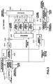
- Picture signal decoding apparatus 102 is constituted as shown in FIG. 3, for example.
- Coded bit stream 400 is temporarily stored into buffer 401.
- This data is read out from buffer 401, and is caused to undergo inverse variable length coding (variable length decoding) by inverse variable length encoder (coder) (IVLC) 402.
- Inverse variable length encoder 402 reads out data in accordance with timing indicated by vbv_delay.
- inverse variable length encoder 402 carries out separation of predictive mode, motion vector and various headers such as temporal_reference, frame_rate, etc.
- Decoded data is inputted to inverse quantizer 403, at which it is inverse-quantized every block in accordance with information (quantization step) taken out from bit stream.
- the inverse-quantized data thus obtained is further caused to undergo inverse DCT (IDCT) at IDCT circuit 404.
- IDCT inverse DCT
- Inverse quantizer 403 and IDCT circuit 404 respectively operate complementarily to quantizer 305 and DCT circuit 304 of FIG. 2.
- Memory controller 410 changes read-out addresses of field memories 411 ⁇ 414 constituting frame memories 416, 417 in correspondence with predictive mode and motion vector separated from inputted data.
- Predictor 415 outputs data which has been read out in correspondence with predictive mode data as it is, or carries out addition thereof.
- data which has been motion-compensated by predictor 415 is inputted to adder 405.
- This adder 405 adds output of predictor 415 to output of IDCT circuit 404 to decode original picture.
- This decode picture is stored into field memories 411 ⁇ 414 as the next predictive picture.
- Display address generator 409 controls read-out addresses of field memories 411 ⁇ 414 so that pictures (frames) are read out in display order indicated by temporal_reference.
- Selector 406 selects picture to be outputted from output picture of adder 405 or output pictures of field memories 411 ⁇ 414 in accordance with temporal_reference.
- Scan converter is a device adapted for converting the number of lines of inputted data to output it to display such as CRT, etc. In this way, bit stream is displayed on display as moving picture.
- periodical signal generator 408 generates frame pulses of interval corresponding to frame_rate in synchronism with, e.g., external periodical signal outputted from display to output them to display address generator 409.
- This display address generator 409 generates display addresses in synchronism with these frame pulses.
- the first embodiment is directed to the case where all of I pictures and respective headers can be read out from picture signal recording/reproducing apparatus even at the time of high speed reproduction.
- picture signal recording/reproducing unit 103 outputs picture signal in conformity with MPEG system to picture signal decoding unit 102 in both cases of normal reproduction and high speed reproduction.
- picture signal decoding unit 102 carries out decode operation similarly to normal reproduction also at the time of high speed reproduction. Namely, all header information such as sequence header, GOP header and picture header, etc. are transmitted at the time of high speed reproduction as well.
- the simplest high speed reproducing method is a method of transmitting intra-frame coded data, i.e., intra-data at the time of high speed reproduction to decode them.
- this method is a method of decoding only I pictures to output them.
- temporal_reference recorded in picture header is different from recorded value in the case of high speed reproduction.
- the other problem is that because normal reproduction is assumed, set vbv_delay does not indicate correct value at the time of high speed reproduction.
- FIG. 8 shows the case where GOP consists of 15 frames and I pictures exist at a rate of one frame to 15 frames.
- I pictures are indicated by slanting lines.
- I pictures are respectively by 3 frames.
- temporal_reference is increased (incremented) by 3 as shown in FIG. 8.
- temporal_reference is increased (incremented) by 1.
- FIG. 9 Picture signal reproducing apparatus (unit) in the first embodiment is shown in FIG. 9.
- Reproducing section 81 may be digital VTR 602 shown in FIG. 6, or digital disc unit 500 shown in FIG. 5.
- picture signal which is read out from reproducing section 81 is outputted to picture signal decoding unit 102 as it is.
- switch 83 is switched by high speed reproduction control signal inputted from the external.
- signal read out from reproducing section 81 is inputted to VLD (IVLC) 84 and header converter 86.
- High speed reproduction control signal is inputted to reproducing section 81, switch 83 and counter 85.
- the reproducing section 81 reproduces predetermined data in accordance with high speed reproduction control signal to output reproduced data.
- the high speed reproduction control signal is a signal indicating that reproduction mode shifts to high speed reproduction mode and a signal indicating reproduction speed.
- VLD VLD
- variable length encoding of MPEG is released and syntax analysis is carried out.
- Counter 85 counts the number of frames to be transmitted. Moreover, this counter 85 outputs temporal-reference for rewriting in accordance with reproduction speed indicated by high speed reproduction control signal.
- Header converter 86 rewrites temporal_reference in picture header in high speed reproduction data delivered from switch 83 in accordance with temporal_reference outputted from counter 85.
- signals delivered from VLD 84 to header converter 86 are signals indicating positions of various headers.
- vbv_delay recorded in picture header indicates timing at which ILVC 402 of decoding unit 102 reads out corresponding picture from buffer 401 at the time of normal reproduction, i.e., buffer occupation ratio of VBV. Since only I picture is read out at the time of high speed reproduction, this vbv_delay does not indicate correct value at the time of high speed reproduction.
- the first method is a method of rewriting vbv_delay to output rewritten one.
- bit counter 87 adds bit quantity of corresponding picture in syntax analysis by VLD 84, and head converter 86 rewrites vbv_delay from that value.
- header converter 86 rewrites vbv_delay into value at the time of high speed reproduction.
- the second method is a method of inserting sequence_start_code (sequence_header) to the leading portions of respective pictures of high speed reproduction data delivered from switch 83, or inserting sequence_end_code to the end potions of respective pictures. This insertion is carried out at header converter 86. Thus, VBV is reset by the leading portion of each picture in picture signal decoding unit 102.
- the third method is a method of converting vbv_delay into "3FFFFFFF" at the time of high speed reproduction.
- vbv_delay indicates that current rate is variable rate. This conversion is carried out at header converter 86.
- VBV is disregarded at the time of decoding in picture signal decoding unit 102.
- picture signal reproducing unit outputs picture signal in conformity with the MPEG system to picture signal decoding unit 102 in both cases of normal reproduction and high speed reproduction.
- picture signal decoding unit 102 carries out decoding similarly to normal reproduction also at the time of high speed reproduction.
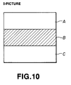
- the second embodiment differs from the first embodiment in that I pictures cannot be completely read out. In the case where read-out speed of reproducing section 81 is not sufficient, it is unable to read out all data of I pictures at the time of high speed reproduction. In this case, only one portion of I picture will be outputted at the time of high speed reproduction.
- FIG. 10 An example of imperfect (incomplete) I picture is shown in FIG. 10.
- data of B portion of I picture in the figure is read out and is decoded, and only portion of intra-data of frame displayed at time earlier by one frame is then changed (altered).
- decoding unit 102 with respect to the portions where no data exists, e.g., A, C in the figure, data of previous frame stored in frame memory 416 or 417 of FIG. 3 is copied and is used.
- the problem in this case is that gap of slice is not allowed in addition to the problem in the case of the first embodiment.
- FIG. 11 shows, in a model form, bit stream.
- predetermined error_start_code (sequence_error_code) prescribed by syntax of MPEG is inserted into the portion or portions where no data exists at header converter 86.
- slice data is transmitted.
- Decoding unit 102 retrieves the next start code when error_start_code is detected at the time of decoding at error start code detector 418 shown in FIG. 3 to start decode operation from that start code. Since slice header has start code, in this case, after error_start_code is detected, such slice comprised of intra data is first decoded. The portion where error_start_code is detected is copied from the same portion of the previous frame stored in frame memory 416 or 417.
- header converter 86 rewrites picture_coding_type into P picture. Moreover, header converter 86 rewrites all variable length coding codes into variable length coding code in P picture. Further, since it is not allowed that data dose not exist at the leading and end macro blocks of slice, macro block types of the leading and end macro blocks of slice where no data exists are caused to be Non-Intra, Not-coded. With respect to macro block type in this case, only macroblock_motion_forward is 1. Namely, VLC code becomes "001".
- a third embodiment of this invention will now be described with reference to FIG. 4.
- the third embodiment is directed to the case where picture header can be read out also at the time of high speed reproduction.
- picture signal decoding unit 112 decodes picture signal in a mode different from that of normal reproduction at the time of high speed reproduction. Explanation will be given in connection with the high speed reproduction mode. At the time of high speed reproduction, VBV is disregarded. In the case where only intra data is transmitted, there is the possibility that buffer 401 of picture signal decoding unit 112 may overflow or underflow. In this case, decoding unit 112 disregards this to decode only decodable data.
- variable length encoder 402 carries out an operation to read out the next data from buffer 401 after decode operation is completed independently of vbv_delay. At the time of high speed reproduction, temporal_reference is disregarded. In addition, it is allowed that any gap between slices exists.
- FIG. 12 shows an example of system configuration by the first transition method.
- control signal is inputted to picture signal decoding unit 112 separately from video bit stream of MPEG. This signal is inputted from the external, and high speed reproduction control signal inputted to reproducing unit 103 is also inputted to picture signal decoding unit 112.
- reproducing unit 103 may be digital VTR 602 shown in FIG. 6, or may be digital disc unit 500 shown in FIG. 5.
- the second mode transition method is a method of writing, into bit stream of MPEG, flag indicating that high speed reproduction data is transmitted.
- flag ff_sequence is recorded into sequence header at the picture signal encoding unit 101.
- FIG. 13 The example where ff_sequence of 1 bit is applied is shown in FIG. 13. It is now assumed that in the case where ff_sequence is "0", that transmit data indicates picture signal of normal reproduction mode. It is further assumed that in the case where ff_sequence is "1", that transmit data indicates picture signal of high speed reproduction mode. When recorded onto recording medium, this ff_sequence is recorded in the state set to "0". (b) of FIG.
- FIG. 12 shows an example of picture signal reproducing unit by the second transition method.
- picture data is read out from reproducing unit 113 in normal reproduction mode to transmit it to picture signal decoding unit 112 through switch 118.
- sequence header is first read out and parameters of picture signal decoding unit 112 are reset.
- picture signal decoding unit 112 decodes transmit data.
- respective parameter values of sequence header are also recorded into register 115.
- picture signal decoding unit 112 undergoes a processing such that parameters are reset in accordance with flag in sequence header. Further, at this time, respective parameter values recorded in sequence header are recorded into register 115.
- parameter values are caused to undergo syntax analysis by VLD 116, and header information is then recorded into register 115.
- header information particularly sequence header is read out also at the time of high speed reproduction, and is recorded into register 115.
- respective parameters are always set to parameter values used when corresponding frame is decoded.
- sequence header is transmitted through formatter 117 and switch 118 for a second time, and picture data at the time of high speed reproduction is then transmitted.
- Sequence header in this case will now be described.
- value of flag of sequence header immediately before is recorded in advance into register 115.
- This value of flag is recorded into sequence header first transmitted after reproduction mode (operation) shifts to high speed reproduction.
- formatter 117 sets ff_sequence of sequence header which has been read out from register 115 to "1".
- value of flag of that sequence header is recorded into register 115.
- ff_sequence of sequence header delivered from picture signal recording unit 113 is set to "0"
- ff_sequence is rewritten into "1".
- values recorded in register 115 are used.
- formatter 117 The formatter converts a current system into a predetermined system at the time of high speed reproduction.
- bit stream is constituted as shown in FIG. 14.
- Inverse variable length encoder 402 of decoding unit 112 detects ff_sequence to designate (inform), when that ff_sequence is "1", respective blocks of decoding unit 112 that reproduction mode is high speed reproduction mode.
- the third embodiment is directed to the case where picture header can be read also at the time of high speed reproduction.
- picture header can be read
- picture signal decoding unit 112 disregards temporal_reference to carry out decoding to output decode picture stored in frame memory 416 or 417 as soon as decode operation is completed. Then, picture signal decoding unit 112 outputs the same picture until decode operation of the next I picture is completed. In this reproduction, only I picture complete as picture is displayed at all times.
- previous_macroblock_address (slice_vertical_position-1) * mb_width-1 Namely, this is address of macro block at the left end of row where the leading macro block of corresponding slice exists. By adding macroblock_address_increment recorded in macro block to that address, it is possible to recognize absolute address of the leading macro block within slice.
- slice to be updated next can be discriminated as absolute address.
- memory controller 410 determines absolute address of slice to be updated on the basis of slice_vertical_position from inverse variable length encoder 402 to control write addresses of frame memories 416 and 417. Namely, in picture signal decoding unit 112, decoded slice data is written into frame memory. In the case where such data is written into frame memory, there are two writing methods described below.
- frame memory corresponding to one frame i.e., any one of frame memories 416 and 417 is used.
- Decoded data of slice is directly overwritten from its absolute address into the frame memory in which picture previously outputted is written.
- data of the frame memory is used at all times.
- frame memory corresponding to 2 frames i.e., both frame memories 416 and 417 are used.
- Decoded data of slice is written into frame memory different from frame memory in which picture previously outputted is written.
- data of the same macro block is copied from the other frame memory.
- pictures are updated by slices which have been read out.
- the fourth embodiment carries out reproduction in a mode different from normal reproduction.
- the method of transition between normal reproduction mode and high speed reproduction mode is similar to that of the third embodiment.
- the fourth embodiment is directed to the case where picture header cannot be decoded or transmitted. In this case, it is necessary to record flag existing in picture header and necessary for decode into slice header to transmit it.
- flag necessary as minimum as possible for inverse variable length encoding is picture_coding_type, intra_dc_precision, picture_structure, q_scale_type, intra_vlc_format, alternate_scan.
- slice_type is flag indicating that corresponding slice consists of intra macro blocks.
- the case of "1" indicates that corresponding slice consists of intra macro blocks.
- the case of "0" indicates that slice includes inter-frame coded macro block (inter-macro block).
- picture_coding_type, intra_dc_precision, picture_structure, q_scale_type, intra_vlc_format, alternate_scan are similar to those of picture header.
- FIG. 15 shows the embodiment where quantizer_matrix is not transmitted. Such quantizer_matrix may be transmitted. Moreover, in the case where quantizer_matrix is not transmitted, default matrix is used.
- Such flag is added to slice header at the time of coding at encoding unit 102, and is recorded onto recording medium.
- picture header information added by VLC 306 at encoding unit 102 is recorded into register 319.
- VLC 306 writes header information recorded in register into respective slice headers.
- a configuration as shown in FIG. 12(b) may be used in place of carrying out processing at the encoding unit side to allow reproduced data to undergo inverse variable length encoding by VLD 116 before inputted to decoding unit 112 to once (temporarily) store picture header thus obtained into register 115 to write it at position of slice header by formatter 117.
- High speed reproduction mode in the fourth embodiment is similar to that of the third embodiment, but carries out decode operation by using flag recorded in slice header also in the case where picture header is unable to be reproduced. Absolute address of slice which has been read out is obtained similarly to the third embodiment. Moreover, since no picture header exists, timing of display after decoding is determined by decoding unit 112. Namely, data in which decoding is completed is always written into the same frame memory, i.e., one of frame memories 416 and 417, and this frame memory is used to display decoded data every time prescribed in frame_rate at timing independent of that at the time of decoding.
- signal in conformity with the MPEG standard is inputted to decoding unit, or signal indicating that reproduction mode shifts to special reproduction is inputted to picture signal decoding unit to transmit flag necessary for special reproduction, thereby making it possible to realize special reproduction such as high speed reproduction, etc.
- signal in conformity with the MPEG standard is inputted to decoding unit, or signal indicating that reproduction mode shifts to special reproduction is inputted to picture signal decoding unit to transmit flag necessary for special reproduction, thereby making it possible to realize special reproduction such as high speed reproduction, etc.
- picture signal recording units e.g., digital VTR, digital video disc, or computer are not therefore required to have picture signal decoding unit, thus advantageously permitting unnecessary circuits to be eliminated.
Landscapes
- Engineering & Computer Science (AREA)
- Multimedia (AREA)
- Signal Processing (AREA)
- Compression Or Coding Systems Of Tv Signals (AREA)
Applications Claiming Priority (4)
| Application Number | Priority Date | Filing Date | Title |
|---|---|---|---|
| JP17192093 | 1993-07-12 | ||
| JP17192093 | 1993-07-12 | ||
| JP171920/93 | 1993-07-12 | ||
| PCT/JP1994/001139 WO1995002946A1 (fr) | 1993-07-12 | 1994-07-12 | Decodeur et procede de decodage |
Publications (3)
| Publication Number | Publication Date |
|---|---|
| EP0664650A1 true EP0664650A1 (fr) | 1995-07-26 |
| EP0664650A4 EP0664650A4 (fr) | 1996-05-15 |
| EP0664650B1 EP0664650B1 (fr) | 2002-05-15 |
Family
ID=15932301
Family Applications (1)
| Application Number | Title | Priority Date | Filing Date |
|---|---|---|---|
| EP19940919894 Expired - Lifetime EP0664650B1 (fr) | 1993-07-12 | 1994-07-12 | Decodeur et procede de decodage |
Country Status (7)
| Country | Link |
|---|---|
| US (1) | US5699474A (fr) |
| EP (1) | EP0664650B1 (fr) |
| JP (1) | JP3470335B2 (fr) |
| KR (1) | KR100289855B1 (fr) |
| AU (1) | AU678490B2 (fr) |
| DE (1) | DE69430617T2 (fr) |
| WO (1) | WO1995002946A1 (fr) |
Cited By (9)
| Publication number | Priority date | Publication date | Assignee | Title |
|---|---|---|---|---|
| EP0720378A2 (fr) * | 1994-12-28 | 1996-07-03 | Sony Corporation | Méthode et appareil de reproduction de données |
| EP0758832A2 (fr) * | 1995-08-11 | 1997-02-19 | Kokusai Denshin Denwa Kabushiki Kaisha | Système de feuilletage rapide pour vidéo |
| GB2303989A (en) * | 1995-07-31 | 1997-03-05 | Samsung Electronics Co Ltd | Using an SDRAM as a frame memory for motion compensation prediction |
| EP0859523A2 (fr) * | 1997-02-17 | 1998-08-19 | Sony Corporation | Procédés et appareil pour enrégistrer et/ou reproduire des signaux numériques |
| EP0888014A2 (fr) * | 1997-06-28 | 1998-12-30 | Deutsche Thomson-Brandt Gmbh | Méthode pour régénérer les données d'origine d'un film vidéo codé numériquement, et dispositif pour mettre en oeuvre la méthode |
| EP0914000A1 (fr) * | 1996-07-24 | 1999-05-06 | SANYO ELECTRIC Co., Ltd. | Dispositif d'enregistrement d'images animees et dispositif de lecture associe |
| EP0936817A2 (fr) * | 1998-02-13 | 1999-08-18 | Matsushita Electric Industrial Co., Ltd. | Appareil et méthode de décodage de données vidéo |
| EP1161097A1 (fr) * | 2000-05-29 | 2001-12-05 | Sony Corporation | Décodeur MPEG |
| EP0902432A3 (fr) * | 1997-09-10 | 2005-08-10 | Sony Corporation | Procédé et appareil d'enregistrement d'information et milieu d'enregistrement d'information |
Families Citing this family (15)
| Publication number | Priority date | Publication date | Assignee | Title |
|---|---|---|---|---|
| KR0165439B1 (ko) * | 1995-09-14 | 1999-03-20 | 김광호 | 디지탈 비디오 테이프 레코더의 화면 구성 장치 및 방법 |
| KR0185932B1 (ko) * | 1995-12-11 | 1999-04-15 | 김광호 | 고속재생을 위한 비디오데이타 복호방법 및 그 장치 |
| JP3263807B2 (ja) * | 1996-09-09 | 2002-03-11 | ソニー株式会社 | 画像符号化装置および画像符号化方法 |
| EP2357829A1 (fr) | 1997-02-13 | 2011-08-17 | Mitsubishi Denki Kabushiki Kaisha | Système de prédiction d'images animées |
| CN100525443C (zh) * | 1997-03-17 | 2009-08-05 | 松下电器产业株式会社 | 发送和接收动态图像数据的方法及其设备 |
| JP3217987B2 (ja) * | 1997-03-31 | 2001-10-15 | 松下電器産業株式会社 | 動画像信号の復号方法および符号化方法 |
| JP3166971B2 (ja) * | 1997-04-01 | 2001-05-14 | 日本ビクター株式会社 | ディジタルデータ記録再生装置及び再生装置 |
| JP3890737B2 (ja) * | 1998-04-14 | 2007-03-07 | 株式会社日立製作所 | ディジタル映像信号または音声信号の再生装置及び再生方法 |
| JP2000078569A (ja) * | 1998-09-03 | 2000-03-14 | Toshiba Corp | 画像データ復号化装置及びその方法 |
| US7237254B1 (en) * | 2000-03-29 | 2007-06-26 | Microsoft Corporation | Seamless switching between different playback speeds of time-scale modified data streams |
| JP4337248B2 (ja) * | 2000-08-31 | 2009-09-30 | ソニー株式会社 | 画像情報の伝送装置、伝送システムおよび伝送方法 |
| US6873786B2 (en) * | 2003-05-05 | 2005-03-29 | Thomson Licensing S.A. | Reverse trick modes on non-progressive video using special groups of pictures |
| JP4442891B2 (ja) * | 2004-11-30 | 2010-03-31 | キヤノン株式会社 | 可変長符号化装置及び可変長符号化方法 |
| US7924923B2 (en) * | 2004-11-30 | 2011-04-12 | Humax Co., Ltd. | Motion estimation and compensation method and device adaptive to change in illumination |
| KR100767669B1 (ko) | 2005-04-04 | 2007-10-18 | 엘지전자 주식회사 | 디지털 멀티미디어 방송 수신장치의 오디오 스트림 저장장치 및 방법 |
Citations (4)
| Publication number | Priority date | Publication date | Assignee | Title |
|---|---|---|---|---|
| EP0546865A2 (fr) * | 1991-12-13 | 1993-06-16 | Kabushiki Kaisha Toshiba | Dispositif d'enregistrement et de reproduction de signaux vidéo numériques |
| EP0617559A2 (fr) * | 1993-03-26 | 1994-09-28 | Matsushita Electric Industrial Co., Ltd. | Appareil d'enregistrement et de reproduction d'un signal vidéo |
| EP0627853A2 (fr) * | 1993-06-03 | 1994-12-07 | Matsushita Electric Industrial Co., Ltd. | Appareil de reproduction d'images et appareil de décodage d'images |
| EP0505985B1 (fr) * | 1991-03-27 | 1999-01-27 | Kabushiki Kaisha Toshiba | Appareil d'enregistrement et reproduction à codage de haute efficacité |
Family Cites Families (6)
| Publication number | Priority date | Publication date | Assignee | Title |
|---|---|---|---|---|
| JPS59141887A (ja) * | 1983-02-03 | 1984-08-14 | Nec Corp | 動画像信号の予測符号化装置 |
| DE3884992T2 (de) * | 1987-04-30 | 1994-05-19 | Nippon Denki Home Electronics | Bildverarbeitungssystem für eine Folge kodierter Signale, die einer Prädiktionskodierung verschiedener Arten unterworfen sind. |
| US5225904A (en) * | 1987-10-05 | 1993-07-06 | Intel Corporation | Adaptive digital video compression system |
| US5231492A (en) * | 1989-03-16 | 1993-07-27 | Fujitsu Limited | Video and audio multiplex transmission system |
| JP2969782B2 (ja) * | 1990-05-09 | 1999-11-02 | ソニー株式会社 | 符号化データ編集方法及び符号化データ編集装置 |
| EP0536630B1 (fr) * | 1991-09-30 | 1999-11-17 | Kabushiki Kaisha Toshiba | Dispositif de traitement de signaux à bande comprimée et magnétoscope |
-
1994
- 1994-07-12 EP EP19940919894 patent/EP0664650B1/fr not_active Expired - Lifetime
- 1994-07-12 KR KR1019950700982A patent/KR100289855B1/ko not_active IP Right Cessation
- 1994-07-12 DE DE69430617T patent/DE69430617T2/de not_active Expired - Lifetime
- 1994-07-12 AU AU70853/94A patent/AU678490B2/en not_active Ceased
- 1994-07-12 US US08/397,116 patent/US5699474A/en not_active Expired - Lifetime
- 1994-07-12 JP JP50446795A patent/JP3470335B2/ja not_active Expired - Fee Related
- 1994-07-12 WO PCT/JP1994/001139 patent/WO1995002946A1/fr active IP Right Grant
Patent Citations (4)
| Publication number | Priority date | Publication date | Assignee | Title |
|---|---|---|---|---|
| EP0505985B1 (fr) * | 1991-03-27 | 1999-01-27 | Kabushiki Kaisha Toshiba | Appareil d'enregistrement et reproduction à codage de haute efficacité |
| EP0546865A2 (fr) * | 1991-12-13 | 1993-06-16 | Kabushiki Kaisha Toshiba | Dispositif d'enregistrement et de reproduction de signaux vidéo numériques |
| EP0617559A2 (fr) * | 1993-03-26 | 1994-09-28 | Matsushita Electric Industrial Co., Ltd. | Appareil d'enregistrement et de reproduction d'un signal vidéo |
| EP0627853A2 (fr) * | 1993-06-03 | 1994-12-07 | Matsushita Electric Industrial Co., Ltd. | Appareil de reproduction d'images et appareil de décodage d'images |
Non-Patent Citations (1)
| Title |
|---|
| See also references of WO9502946A1 * |
Cited By (21)
| Publication number | Priority date | Publication date | Assignee | Title |
|---|---|---|---|---|
| CN1091921C (zh) * | 1994-12-28 | 2002-10-02 | 索尼公司 | 数据再现的方法和装置 |
| EP0720378A3 (fr) * | 1994-12-28 | 1997-06-25 | Sony Corp | Méthode et appareil de reproduction de données |
| EP0720378A2 (fr) * | 1994-12-28 | 1996-07-03 | Sony Corporation | Méthode et appareil de reproduction de données |
| GB2303989A (en) * | 1995-07-31 | 1997-03-05 | Samsung Electronics Co Ltd | Using an SDRAM as a frame memory for motion compensation prediction |
| GB2303989B (en) * | 1995-07-31 | 1998-06-17 | Samsung Electronics Co Ltd | Frame memory in motion picture decoder |
| US5910824A (en) * | 1995-07-31 | 1999-06-08 | Samsung Electronics Co., Ltd. | Frame memory for a motion picture decoder |
| EP0758832A2 (fr) * | 1995-08-11 | 1997-02-19 | Kokusai Denshin Denwa Kabushiki Kaisha | Système de feuilletage rapide pour vidéo |
| EP0758832A3 (fr) * | 1995-08-11 | 1998-02-11 | Kokusai Denshin Denwa Kabushiki Kaisha | Système de feuilletage rapide pour vidéo |
| EP0914000A1 (fr) * | 1996-07-24 | 1999-05-06 | SANYO ELECTRIC Co., Ltd. | Dispositif d'enregistrement d'images animees et dispositif de lecture associe |
| EP0914000A4 (fr) * | 1996-07-24 | 2001-10-31 | Sanyo Electric Co | Dispositif d'enregistrement d'images animees et dispositif de lecture associe |
| EP0859523A2 (fr) * | 1997-02-17 | 1998-08-19 | Sony Corporation | Procédés et appareil pour enrégistrer et/ou reproduire des signaux numériques |
| EP0859523A3 (fr) * | 1997-02-17 | 2000-04-19 | Sony Corporation | Procédés et appareil pour enrégistrer et/ou reproduire des signaux numériques |
| US6115341A (en) * | 1997-02-17 | 2000-09-05 | Sony Corporation | Digital signal recording method and apparatus and digital signal reproduction method and apparatus |
| EP0888014A2 (fr) * | 1997-06-28 | 1998-12-30 | Deutsche Thomson-Brandt Gmbh | Méthode pour régénérer les données d'origine d'un film vidéo codé numériquement, et dispositif pour mettre en oeuvre la méthode |
| EP0888014A3 (fr) * | 1997-06-28 | 2000-02-23 | Deutsche Thomson-Brandt Gmbh | Méthode pour régénérer les données d'origine d'un film vidéo codé numériquement, et dispositif pour mettre en oeuvre la méthode |
| US6438318B2 (en) | 1997-06-28 | 2002-08-20 | Thomson Licensing S.A. | Method for regenerating the original data of a digitally coded video film, and apparatus for carrying out the method |
| EP0902432A3 (fr) * | 1997-09-10 | 2005-08-10 | Sony Corporation | Procédé et appareil d'enregistrement d'information et milieu d'enregistrement d'information |
| EP0936817A2 (fr) * | 1998-02-13 | 1999-08-18 | Matsushita Electric Industrial Co., Ltd. | Appareil et méthode de décodage de données vidéo |
| EP0936817A3 (fr) * | 1998-02-13 | 2003-05-14 | Matsushita Electric Industrial Co., Ltd. | Appareil et méthode de décodage de données vidéo |
| EP1161097A1 (fr) * | 2000-05-29 | 2001-12-05 | Sony Corporation | Décodeur MPEG |
| US7292772B2 (en) | 2000-05-29 | 2007-11-06 | Sony Corporation | Method and apparatus for decoding and recording medium for a coded video stream |
Also Published As
| Publication number | Publication date |
|---|---|
| KR950703839A (ko) | 1995-09-20 |
| US5699474A (en) | 1997-12-16 |
| JP3470335B2 (ja) | 2003-11-25 |
| AU678490B2 (en) | 1997-05-29 |
| WO1995002946A1 (fr) | 1995-01-26 |
| EP0664650B1 (fr) | 2002-05-15 |
| AU7085394A (en) | 1995-02-13 |
| EP0664650A4 (fr) | 1996-05-15 |
| DE69430617T2 (de) | 2002-12-05 |
| DE69430617D1 (de) | 2002-06-20 |
| KR100289855B1 (ko) | 2001-05-15 |
Similar Documents
| Publication | Publication Date | Title |
|---|---|---|
| EP0664650B1 (fr) | Decodeur et procede de decodage | |
| KR100291404B1 (ko) | 디지탈 기록 재생 장치 | |
| US5786858A (en) | Method of encoding image signal, apparatus for encoding image signal, method of decoding image signal, apparatus for decoding image signal, and image signal recording medium | |
| KR100796085B1 (ko) | 복호 장치, 복호 방법, 및 기록 매체 | |
| KR100676093B1 (ko) | 비디오 데이터 기록 장치, 비디오 데이터 기록 방법,비디오 데이터 재생 장치, 비디오 데이터 재생 방법,비디오 데이터 기록 및 재생 장치, 및 비디오 데이터 기록및 재생 방법 | |
| JPH089319A (ja) | ディジタルビデオ信号の記録方法、記録装置及び再生装置 | |
| JP3277713B2 (ja) | ディジタルビデオ信号の記録装置、記録再生装置及び再生装置 | |
| US6314139B1 (en) | Method of inserting editable point and encoder apparatus applying the same | |
| JP3147792B2 (ja) | 高速再生のためのビデオデータの復号化方法及びその装置 | |
| KR100195096B1 (ko) | 트릭 플레이를 위한 디지탈 비디오 테이프의 기록/재생 방법 및 그 장치 | |
| JPH08140042A (ja) | 画像データの再生装置及び記録再生装置 | |
| KR100796885B1 (ko) | 신호 프로세서 | |
| JP2000138897A (ja) | データ処理装置およびデータ記録装置 | |
| KR100739262B1 (ko) | 기록 장치 및 기록 방법과, 재생 장치 및 재생 방법 | |
| EP0637888A2 (fr) | Appareil d'enregistrement de codes | |
| US20020071491A1 (en) | Signal processor | |
| EP0634868A1 (fr) | Procede de codage de signal d'image, codeur de signal d'image, procede de decodage de signal d'image, decodeur de signal d'image et support d'enregristrement de signal d'image | |
| JP4468497B2 (ja) | ディジタル符号化ビデオフィルムの原データを再生する方法及び装置 | |
| JP3334354B2 (ja) | ディジタルビデオ信号の変速再生方法及び再生装置 | |
| KR100681992B1 (ko) | 기록 장치 및 방법 | |
| JPH0898142A (ja) | 画像再生装置 | |
| JPH06339113A (ja) | 動画像記録再生装置 | |
| JP3167590B2 (ja) | ディジタル記録再生装置 | |
| JPH08130715A (ja) | 画像再生装置 | |
| KR0183812B1 (ko) | 트릭 플레이를 위한 디지탈 비디오 테이프의 기록 및 재생 장치 |
Legal Events
| Date | Code | Title | Description |
|---|---|---|---|
| PUAI | Public reference made under article 153(3) epc to a published international application that has entered the european phase |
Free format text: ORIGINAL CODE: 0009012 |
|
| 17P | Request for examination filed |
Effective date: 19950314 |
|
| AK | Designated contracting states |
Kind code of ref document: A1 Designated state(s): DE FR GB IT |
|
| A4 | Supplementary search report drawn up and despatched | ||
| AK | Designated contracting states |
Kind code of ref document: A4 Designated state(s): DE FR GB IT |
|
| 17Q | First examination report despatched |
Effective date: 19980918 |
|
| GRAG | Despatch of communication of intention to grant |
Free format text: ORIGINAL CODE: EPIDOS AGRA |
|
| GRAG | Despatch of communication of intention to grant |
Free format text: ORIGINAL CODE: EPIDOS AGRA |
|
| GRAH | Despatch of communication of intention to grant a patent |
Free format text: ORIGINAL CODE: EPIDOS IGRA |
|
| GRAH | Despatch of communication of intention to grant a patent |
Free format text: ORIGINAL CODE: EPIDOS IGRA |
|
| GRAA | (expected) grant |
Free format text: ORIGINAL CODE: 0009210 |
|
| AK | Designated contracting states |
Kind code of ref document: B1 Designated state(s): DE FR GB IT |
|
| REG | Reference to a national code |
Ref country code: GB Ref legal event code: FG4D |
|
| REF | Corresponds to: |
Ref document number: 69430617 Country of ref document: DE Date of ref document: 20020620 |
|
| ET | Fr: translation filed | ||
| PLBE | No opposition filed within time limit |
Free format text: ORIGINAL CODE: 0009261 |
|
| STAA | Information on the status of an ep patent application or granted ep patent |
Free format text: STATUS: NO OPPOSITION FILED WITHIN TIME LIMIT |
|
| 26N | No opposition filed |
Effective date: 20030218 |
|
| REG | Reference to a national code |
Ref country code: GB Ref legal event code: 746 Effective date: 20091124 |
|
| PGFP | Annual fee paid to national office [announced via postgrant information from national office to epo] |
Ref country code: GB Payment date: 20120719 Year of fee payment: 19 |
|
| PGFP | Annual fee paid to national office [announced via postgrant information from national office to epo] |
Ref country code: IT Payment date: 20120731 Year of fee payment: 19 Ref country code: FR Payment date: 20120806 Year of fee payment: 19 Ref country code: DE Payment date: 20120720 Year of fee payment: 19 |
|
| GBPC | Gb: european patent ceased through non-payment of renewal fee |
Effective date: 20130712 |
|
| REG | Reference to a national code |
Ref country code: FR Ref legal event code: ST Effective date: 20140331 |
|
| PG25 | Lapsed in a contracting state [announced via postgrant information from national office to epo] |
Ref country code: DE Free format text: LAPSE BECAUSE OF NON-PAYMENT OF DUE FEES Effective date: 20140201 Ref country code: GB Free format text: LAPSE BECAUSE OF NON-PAYMENT OF DUE FEES Effective date: 20130712 |
|
| REG | Reference to a national code |
Ref country code: DE Ref legal event code: R119 Ref document number: 69430617 Country of ref document: DE Effective date: 20140201 |
|
| PG25 | Lapsed in a contracting state [announced via postgrant information from national office to epo] |
Ref country code: FR Free format text: LAPSE BECAUSE OF NON-PAYMENT OF DUE FEES Effective date: 20130731 Ref country code: IT Free format text: LAPSE BECAUSE OF NON-PAYMENT OF DUE FEES Effective date: 20130712 |