EP0664068B1 - Netzwerkstruktur und signalisierungsprotokoll für ein fernmeldenetz - Google Patents
Netzwerkstruktur und signalisierungsprotokoll für ein fernmeldenetz Download PDFInfo
- Publication number
- EP0664068B1 EP0664068B1 EP93919751A EP93919751A EP0664068B1 EP 0664068 B1 EP0664068 B1 EP 0664068B1 EP 93919751 A EP93919751 A EP 93919751A EP 93919751 A EP93919751 A EP 93919751A EP 0664068 B1 EP0664068 B1 EP 0664068B1
- Authority
- EP
- European Patent Office
- Prior art keywords
- software
- network
- equipment
- telephone
- signalling
- Prior art date
- Legal status (The legal status is an assumption and is not a legal conclusion. Google has not performed a legal analysis and makes no representation as to the accuracy of the status listed.)
- Expired - Lifetime
Links
- 230000011664 signaling Effects 0.000 title claims abstract description 113
- 238000000034 method Methods 0.000 claims description 44
- 238000012545 processing Methods 0.000 claims description 2
- 238000004891 communication Methods 0.000 abstract description 8
- 108091006146 Channels Proteins 0.000 description 14
- 238000012546 transfer Methods 0.000 description 10
- 230000004044 response Effects 0.000 description 6
- 230000000977 initiatory effect Effects 0.000 description 5
- 238000004458 analytical method Methods 0.000 description 4
- 230000009286 beneficial effect Effects 0.000 description 4
- 230000000694 effects Effects 0.000 description 4
- 230000008901 benefit Effects 0.000 description 3
- 230000005540 biological transmission Effects 0.000 description 3
- 230000008859 change Effects 0.000 description 3
- 230000008569 process Effects 0.000 description 3
- 238000006243 chemical reaction Methods 0.000 description 2
- 230000008878 coupling Effects 0.000 description 2
- 238000010168 coupling process Methods 0.000 description 2
- 238000005859 coupling reaction Methods 0.000 description 2
- 230000007246 mechanism Effects 0.000 description 2
- 238000010276 construction Methods 0.000 description 1
- 230000001419 dependent effect Effects 0.000 description 1
- 238000011835 investigation Methods 0.000 description 1
- 238000012423 maintenance Methods 0.000 description 1
- 230000004048 modification Effects 0.000 description 1
- 238000012544 monitoring process Methods 0.000 description 1
- 230000000717 retained effect Effects 0.000 description 1
- 230000007727 signaling mechanism Effects 0.000 description 1
- 239000013589 supplement Substances 0.000 description 1
Images


Classifications
-
- H—ELECTRICITY
- H04—ELECTRIC COMMUNICATION TECHNIQUE
- H04Q—SELECTING
- H04Q3/00—Selecting arrangements
- H04Q3/0016—Arrangements providing connection between exchanges
- H04Q3/0025—Provisions for signalling
-
- H—ELECTRICITY
- H04—ELECTRIC COMMUNICATION TECHNIQUE
- H04Q—SELECTING
- H04Q3/00—Selecting arrangements
-
- H—ELECTRICITY
- H04—ELECTRIC COMMUNICATION TECHNIQUE
- H04Q—SELECTING
- H04Q3/00—Selecting arrangements
- H04Q3/0016—Arrangements providing connection between exchanges
Definitions
- the present invention relates to a method of signaling between software in different equipment in a telecommunication network and to a telecommunication network for carrying out the signaling method.
- the invention relates to telecommunication networks in which functions are distributed between telephone exchanges and how the functions communicate with one another. Those rules and conventions that are applied when the functions communicate with one another are referred to as protocol.
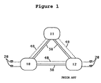
- Figure 1 illustrates how telephone exchanges are placed in a telephone network.
- Reference numerals 10 and 12 identify two local exchanges to which subscribers 20 are connected.
- Reference numeral 11 identifies a transit exchange which is capable of connecting traffic between different local exchanges.
- the telephone exchanges 10, 11, 12 in the network illustrated in Figure 1 are connected to one another by means of trunk connections 30.
- the telephone exchange 11 in the specific network shown in Figure 1 is a tandem exchange, because direct trunk lines are found between all local exchanges.
- the feature of interest in the Figure 1 network is that traffic can be moved between the local exchanges 10 and 12 through the tandem exchange 11.
- the reference numeral 40 identifies signalling connections for so-called common channel signalling. A typical feature of present-day telephone networks is that the signalling connections are separate from the trunk connections.
- signalling is effected on the trunk connections, for instance with tones on the trunk connection between the exchanges.
- the signalling network has been separated from the trunk connections in latter-day techniques.
- Signalling in the telephone network takes place between the network telephone exchanges and is intended to control the traffic, including among other things the transfer of cradle-switched subscriber states and of address information relating to called subscribers.
- FIG 2 illustrates generally one of the telephone exchanges 10, 11 or 12 of the telephone network illustrated in Figure 1. More specifically, only those functions which are relevant to technical problems that are fundamental to the present invention are described.
- the telephone exchange in this case the local exchange 10, comprises a computer 100 which controls coupling equipment.
- the coupling equipment comprises a subscriber interface 101, switching equipment 102, and a trunk connection interface 103.
- the switching equipment 102 functions to connect telephone channels for telephone calls between the subscriber interface 101 and the trunk connection interface 103.
- a computer 100 controls signalling from the subscriber 20 to the local exchange 10, via a subscriber line 25 and the subscriber interface 101.
- the computer 100 controls connection of trunk circuits 30 to the switching equipment 102 via the trunk connection interface 103.
- the computer 100 also has an interface 104 towards the signal network, via a signal terminal.
- the computer performs a number of items of software 110 which have different functions in the telephone exchange, such as to control the connection of calls or maintenance functions, for instance the collection of billing information.
- These items of software 110 can signal with items of software in other telephone exchanges, via the signal terminal 104.
- the protocols referenced P40 in Figure 2 are used. These protocols are thus used in the signal connections 40, although they are shown separately in Figure 2.
- the signalling technique that predominates in telephone networks today is based on common channel signalling in accordance with CCITT or ANSI recommendations.
- the B-subscriber in the local exchange 12, there is used a so-called circuit related signalling process, in which a trunk connection 30 is selected between the telephone exchanges 10 and 12 and in which signalling refers to a selected circuit in the trunk line.
- a time slot that is able to transmit a telephone call.
- the signals are transmitted with reference to this time slot and signalling takes place with a protocol P40 that can be interpreted by respective software in the two telephone exchanges.
- the connection is not effected directly from software to software in the telephone exchange 10 and 12, and instead the telephone exchange 10 signals to the telephone exchange 12 by referring to the chosen physical circuit that is used.
- the protocol used when signalling is, for instance, TUP (Telephony User Part) or ISUP (Integrated Services Digital Network User Part).
- TUP Transmission Control User Part
- ISUP Integrated Services Digital Network User Part
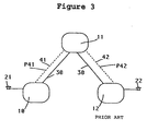
- FIG 3 illustrates simply a transit case between three telephone exchanges, i.e. between two local telephone exchanges 10 and 12 and a transit exchange 11, which passes traffic between the local exchanges 10 and 12.
- the A-subscriber 21 in the local exchange 10 has requested a call to the B-subscriber 22 in the other local exchange 12.
- the call connection between the local exchanges 10 and 11 is divided into two connection halves which are mutually connected in the transit exchange.
- the local exchange 10 selects a trunk circuit to the transit exchange 11 and uses a protocol P41 to establish one half of the connection to the transit exchange 11.
- the transit exchange 11 establishes a connection half to the local exchange 12, by selecting a trunk circuit on the trunk line 30 and using a protocol P42 to establish the other connection path to the local exchange 12.
- the transit exchange 11 connects the call from the A-subscriber 21 and is, in principle, transparent to the call.
- the telephone service offered to subscribers 21 and 22 is dependent on the software in all telephone exchanges 10, 11, 12 active in a connection and also on those protocols P41 and P42 that are used by the exchanges for communication therebetween. If a new function is to be introduced, for instance automatic callback in the event of an engaged number, it is necessary for this function to be implemented in the software in all telephone exchanges that are active in the process of establishing a connection from subscriber A to subscriber B, and also that the protocol P41 and the protocol P42 used between the software are capable of handling and controlling the new function. Thus, it is necessary to modify all three telephone exchanges and all protocols when introducing a new function.
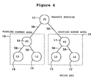
- telephone numbers and telephone networks are built-up hierarchically, so that different parts of a telephone number relate to different geographical regions and areas. Normally, outlying regions are preceded with an area routing number which corresponds to a routing number area serving as a routing number exchange which handles incoming traffic to all subscribers located within this routing number area. Further parts of the telephone number, normally the first two or three digits of the number, are used to identify the local exchange to which given subscribers are connected.
- FIG. 4 there is shown a number of local telephone exchanges 10, 12, 14, 15, of which exchanges 10 and 14 are connected to a routing number exchange 16 located in a routing number area 18, whereas the local telephone exchanges 10 and 15 are connected to another routing number telephone exchange 17 which is located in another routing number area 19.
- the routing number telephone exchanges 16 and 17 are connected to a transit exchange 11. Assume that a telephone call shall be connected from one subscriber belonging to exchange 10, furthest to the left in Figure 4, to a subscriber connected to the local exchange 12, furthest to the right in Figure 4.
- the local exchange 10 will not recognize the B-number of the subscriber in the local exchange 12, but will transfer the B-number to its routing number exchange 16, which in turn recognizes that the number is concerned with another routing number area and therefore transfers the call to a transit exchange 11.
- the transit exchange 11 passes the call to the routing number area of the B-subscriber, more specifically to the routing number exchanges 17 in the routing number area 19.
- the routing number exchange 17 analyzes further parts of the B-number, in order to establish the local exchange to which the B-subscriber is connected, and switches the call to this local exchange, in the illustrated case the local exchange 12.
- the disadvantage with this type of telephone call routing procedure is that a subscriber is forced to change telephone numbers when he moves between the areas served by different telephone exchanges.
- a subscriber may also be forced to change his telephone number when it is necessary to move his connection from one telephone exchange to another in conjunction with restructuring or extending the telephone network. This represents a disadvantage to the individual subscriber and may also involve additional costs to the network manager, who must plan restructuring of the network in good time and inform all subscribers concerned with this restructuring of the changes that will be made to the subscriber numbers. Information of this nature incurs heavy costs.
- Modern telephone networks include a further possibility of signalling directly between telephone exchanges and other equipment in the telephone network.
- Such signalling is based on the ability of the software in a telephone exchange or in some other equipment to address functions directly in another telephone exchange or in some other equipment.
- This enables purely signal channels to be established between different items of equipment in the telephone network, without relating the signalling process to a trunk circuit when connecting a call.
- This direct addressing procedure is used typically to address central functions in the telephone network, such as so-called free-phone services (In Sweden 020-numbers, in the U.S.A. 800-numbers) or to call subscriber data bases in the mobile telephone network.
- Figure 5 shows a typical example which includes the same units as those shown in Figure 3 with the addition of central equipment 13 which permits conversation to be made with the aid of a protocol P43 which is tailored to the functionality provided by equipment 13.
- This protocol P43 is separate from the protocols P41 and P42.
- the telephone exchange 10 discovers that it is unable to handle the number requested and therefore transfers the call to the telephone exchange 11, which discovers that the call is directed to a directory number which requires particular treatment, and therefore calls the software in the central equipment 13 which can handle this directory number.
- the equipment 13 typically a network data base, responds to the query from the telephone exchange 11 by disclosing the telephone number to which the call from subscriber 21 shall be routed.
- Signalling between the telephone exchanges 11 and 13 is not circuit-related, and when the telephone exchange 11 has learned of the destination to which the call shall be routed, signalling is effected to the relevant telephone exchange with the aid of circuit-switched signalling in the aforedescribed manner.
- the use of free signalling when calling software in the equipment 13 in order to obtain an answer to where a requested functionality is found in the network can be employed to solve the problem with the fixed relationship of a telephone number with the geographical location of a subscriber when the equipment 13 is comprised of a network data base which keeps an account of where the subscribers are located.
- US-A-5 048 081 relates to a method of replacing an existing exchange with a new exchange in a controlled manner by gradually moving the subscriber lines to the new exchange.
- Two different exchanges shall thus convert, in a transparent manner to the surrounding telephone network, the so called destination point codes and the originating point codes and the circuit identifying codes. These codes are present in signaling messages which the exchanges receive over a signaling network via a signal transfer point.
- a point code converter is used which receives a message, analyses its address and forwards it either to the existing exchange or to the new exchange. The message redirection thus taking place is made by the point code converter.
- the present invention relates to the provision of a network structure and used protocols for a telecommunication system with which the aforesaid drawbacks encountered when practicing present standpoints of techniques are eliminated.
- the invention relates to a method of arranging signalling between telephone exchanges in a telecommunication network with the intention of:
- signalling between the telephone exchanges of the telecommunication network is characterized by seven points:
- Figure 6 illustrates an inventive network structure by means of which all nodes in the network whose software is capable of communicating with one another are able to establish signalling connections therebetween.
- the nodes are referenced 10, 11 and 12 and are the same nodes as those illustrated in Figure 5, for instance.
- the novelty of the network shown in Figure 6 resides in that all telephone exchanges that are intended to communicate mutually also have a signalling connection.
- the signalling connections 41 and 42 with the protocols P41 and P42 are the same as those shown in Figure 5, while the novelty resides in a direct signalling connection 50 between the local exchanges or nodes 10 and 12.
- FIG. 7 illustrates an example in which signalling can take place over an off-line signalling network with the aid of a signal switching node 60 which is connected to the nodes 10, 11, 12 in the telecommunication network via signalling paths or connections 51, 52, 53.
- the network exchanges can be referred to as signal points, SP, and the signal switching node functions as a switch in the signal network, in the same manner as an STP (Signal Transfer Point) in common channel signalling procedures according to CCITT and ANSI recommendations.
- STP Signal Transfer Point
- the signal switching node reads the address of a message and routes the message further in the signal network.
- the signal network is a free-standing or off-line network in relation to the switching network formed by the trunk connections.
- the signal links will not be shown in the following Figures, which consequently show only those protocols that are used in signalling processes. Only those signal paths which can be established over the signal network will be shown. Figures 6 and 7 thus illustrate the physical signalling network. If all signal links were to be shown in the following Figures, the Figures would become extremely obscure.
- the software 100 in Figure 2 is divided into two groups of software, i.e. a connection-related group 210 and service-related software groups 220, in the manner illustrated in Figure 8.
- the group 210 will have the protocol 211 and the group 220 the protocol 221.
- the gains achieved by dividing the software in this way are evident from Figure 9, which illustrates a network constructed in accordance with the invention.
- the software of respective nodes 10, 11 and 12 is constructed from the aforesaid two groups of connection-related software and service-related software 210, 220.
- the service-related software group 220 directly establishes protocol P221 between the service-related software in those telephone exchanges 10 and 12 which handle the subscribers 21, 22 for which a telephone call shall be connected.
- protocol P221 between the service-related software in those telephone exchanges 10 and 12 which handle the subscribers 21, 22 for which a telephone call shall be connected.
- the connection-related groups of software 210 will communicate from exchange to exchange with the aid of the protocol P211 in the manner of present-day telephone exchanges, so as to establish trunk connections 30 between the exchanges. It is thus the trunk connections 30 which carry the telephone calls.
- service-related software 220 can only be added to, for instance, those telephone exchanges which handle subscribers in a given company and, in this way, offer the company subscribers special services, since no direct signal paths are found between these telephone exchanges, these signal paths being used for service control.
- the connection or signalling paths between these telephone exchanges can then be permitted to pass over selected telephone exchanges in the network.
- the callback service or the card number service can only be added to the exchanges 10 and 12 in Figure 9, i.e. to those exchanges to which the subscribers concerned are connected, whereas other exchanges in the network, in the illustrated case the transit exchange 11, need not have knowledge of these services and will not therefore have protocol which supports the newly added services. In other words, it is easier to add new services to the telephone network.
- Figure 9 illustrates an example of a principle central to the present invention, namely the principle of dividing signalling into two parts.
- FIG. 10 illustrates two groups of service-related, or service-controlling, software, namely the software groups 220A and 220B.
- These groups are found in the two telephone exchanges in the network which form the terminal points of a connection and which, in accordance with the invention, have a direct signal path therebetween.
- signalling i.e. the total protocol
- the software 230 and 232 on respective sides of the connection are able to communicate over this signal path with a protocol 241 which is carried by a basic protocol (described below) along the signal path between the respective software groups 220a and 220b.
- the software is that which handles a call from the A-subscriber at a given moment in time.
- the signal path passes between the groups 220a and 220b of software which control, or handle, the A-subscriber call and the B-subscriber call at a given moment in time.
- the signal path is controlled with the aid of the basic protocol 240 and is used to carry protocol of type 241 between the software in the groups 220a and 220b.
- protocols other than the aforesaid protocol dialogues 241 can be added.
- These additional protocol dialogues 241 are protocols which enable software in the group 220a to communicate with software in the group 220b. These dialogue protocols 241 are specific to each specific service and specific functionality respectively. For instance, a dialogue protocol can be used for standard telephony, so called POTS, while another protocol may be used for the callback service feature, and a third protocol can be used for transferring a call when the number called is engaged, and so on.
- 240 identifies a basic protocol which can be used to establish a signal path between the groups 220a and 220b.
- a special protocol can be established between those groups of software which shall communicate with one another via the established signal path, for instance groups 230 and 232 in Figure 10.
- the aforesaid dialogue protocols 241 are thus established along the signal path 240.
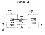
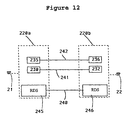
- Figure 11 is an illustration similar to the Figure 10 illustration and shows the possibility of parallel dialogues 241 and 242 which pass along the same signal path, with the aid of the group protocol or basic protocol 240.
- the dialogue 241 is a POTS-dialogue
- the dialogue 242 may be a callback service where the A-subscriber 21 requests the B-subscriber 22 to be called back, wherewith corresponding software 235 request monitoring of the B-subscriber.
- the software 236 informs the software 235 to this effect with an operation in the dialogue protocol 242 and the software 235 handles the response to the callback request.
- Figure 12 illustrates the same subject matter as Figure 11, although in this case there is shown the basic protocol (RDS) controlled, or handled, by a separate handler 245 and 246.
- RDS basic protocol
- handlers 245, 246 thus establish a signal path between the group 220a and the group 220b for a given telephone call connection, and also manage the establishment of dialogues on this signal path.
- Figure 13 illustrates the manner in which the signal path is established between two groups 220a and 220b.
- the software 230 endeavours to establish a signal path to the software group 220b which handles the B-subscriber in the telephone exchange 12.
- the software 230 is included in the group of service-related software 220A.
- the software 230 requests its handler 245 to establish a 241-type dialogue with the group 220b in the telephone exchange 12.
- the call from the software 230 includes a first initiating operation of the dialogue 241 and the signalling service handler 245 packs the initiating operation in a message INITIATE in the basic protocol 240 used to establish signal paths and dialogues.
- the message INITIATE and the initiating operation are sent to corresponding handlers 246 in the receiving telephone exchange 12.
- the message INITIATE includes a request to establish a signal path and to start a given, specified type of dialogue 241.
- INITIATE carries with it a first operation in the desired dialogue.
- the signalling service handler i.e. the handler 246 in the receiving group 220b receives the INITIATE-message and calls a handler 250 which corresponds to the requested dialogue/functionality on the basis of the type of dialogue requested.
- the handler 250 implemented in software form, functions (a) to redirect signal path establishment to a final destination, when applicable and in the manner described in more detail below, and (b) to start the group 220b of software which shall control the B-subscriber in the call connection, when the final destination has been reached.
- the handler 250 analyzes the INITIATE-message in order to ascertain the dialogue requested, and on the basis of the result of the analysis the establishing handler 250 can choose to:
- the telephone exchange 12 When the signal path establishing handler 250 in the telephone exchange is, for instance, a data base or coacts with a data base, the telephone exchange 12 will thus contain the information necessary for achieving redirection of a request for the establishment of a call connection.
- This network data base will, for instance, keep an account of all subscriber numbers within a certain geographical area, for instance.
- the advantage achieved by establishing a signal path in this way is that the originally called computer software 230 is not influenced by whether the initially indicated telephone exchange 12 is the local exchange which controls the B-subscriber or whether one or more network data base functions are activated in order to identify which telephone exchange shall control or handle the call.
- the software 235 commands the signalling service handler 245 on the A-subscriber side to establish a further dialogue along the signal path.
- a first operation is added along the dialogue together with this request.
- the handler 245 on the A-subscriber side will then pack a BEGIN-message in this operation to the handler 246 on the B-subscriber side.
- the handler 246 will then establish new dialogue on the B-subscriber side and deliver the transmitted operation to the software group 220b which controls the B-subscriber side.
- these software programs in the software group 220b decide which software shall handle signalling of the new dialogue. This latter software receives the operation from the software 235 on the A-subscriber side. It is assumed in this case that a separate software program 236 is started for handling the callback request and that this software 236 will communicate with the software 235 via the established dialogue.
- the dialogue in progress is stopped in the following way: It is assumed that the software 232 takes the initiative in stopping the dialogue 241, with the aid of the software 230.
- the software 232 then commands the handler on the B-subscriber side to stop the dialogue. This command may carry to the software 230 a last operation, in a manner corresponding to the establishment of dialogue.
- the handler 246 on the B-subscriber side packs this last operation in an END-message to the handler 245 on the A-subscriber side.
- the dialogue between the software 230 and the software 232 stops herewith. Subsequent to having stopped the last dialogue on a signal path in accordance with the above, the handlers 245 and 246 dismantle the signal path.
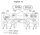
- the aforedescribed redirection principle can be applied in many different ways to construct a telephone network. A number of these are illustrated below. Redirection is used generally to release the telephone number of a subscriber from a geographically fixed telephone exchange. According to the present invention, the known telephone routing principle described with reference to Figure 4 can be replaced with a hierarchy of data bases in the manner illustrated in Figure 15. Instead of connecting traffic to routing number exchanges 16, 17, as the case of the Figure 4 illustration, there is used a hierarchy of data bases 300, 310, 320, 330 which are used to establish signalling directly between the local exchanges 10, 14, 15, 12. The speech connection is then established in an optimal manner between the telephone exchanges concerned.
- Each region includes a regional data base 300 in region 350, and a regional data base 310 in region 360.
- the regional data base keeps an account of where all subscribers in its region are connected at that moment in time.
- the regional data base 310 keeps an account of all subscribers in its region 360 and is aware of which local exchanges 12, 15 these subscribers are connected at that moment in time.
- Upwards in the hierarchy are also found national data bases, for instance a data base 320 for telephone subscribers, another national data base 330 for mobile subscribers. All national traffic is handled over these national data bases, for instance when a subscriber in region 350 wishes to communicate with a subscriber in region 360.
- the connection between the national number of the subscriber and the routing number area can be retained, while within the routing number area, i.e. within the region 350, for instance, some form of connection between the subscriber number and a specific telephone exchange within the routing number area is provided.
- a subscriber can thus retain its telephone number when moving within the routing number area and therewith switch connection from one local exchange to another. It is therewith possible to avoid the aforesaid drawbacks that are encountered when extending the telephone network, for instance.
- total release of the telephone number of a subscriber from a geographically fixed local telephone exchange also includes the routing numbers
- the telephone number it is possible for the telephone number to be no longer bound to a specific telecommunication network, in other words, to use one and the same "telephone number" both in the telephone network and, for instance, in the mobile telephony network, or in a data packet network or a person-paging network, etc.
- a person can be allocated a "personal telephone number" which will enable the person to be reached irrespective of the network in which said person is located and the location in the network in which the person can be found at that particular time.
- the practical expedients with which these solutions can be achieved are known to the art.
- a so-called "smart card” which when inserted into a telephone set will provide the network data base with information to the effect that the person holding the card can be reached at this telephone set at that particular time.
- the "telephone number” is therefore connected to the card holder (person) and not to the telephone set. It is possible in this way for the network to divulge that the person concerned is at home, in the office, or is out-and-about and carries a mobile telephone, wherewith the mobile telephone informs the network of its location in the mobile telephony network with the aid of known signalling procedures.
- the technique involving the use of data bases can also be employed on a lower level, for instance on a company level, in order to keep an account of the whereabouts of a given person within the company at any particular moment in time.
- each company employee is allocated a "company number" and retains this number during the full term of his/her employment within the company, irrespective of whether the person concerned later moves within the company, either within one and the same building or between buildings within one and the same region in those cases where different buildings are connected to different local exchanges, or whether the person concerned moves between company buildings which are located within different regions 350, 360.
- This method obviates the need for incoming traffic to company employees being handled centrally by the company in a central switchboard, as is often the case in present-day telephone networks.
- the company data base keeps an account of the whereabouts of a given person at any particular moment in time and redirects the traffic to the location of the person concerned.
- a signal path is first connected between the A-subscriber and the B-subscriber with the use of information contained in the data base and only then is a connection path, for instance a speech channel, established between the A and B subscribers.
- This speech channel can then always be established in the most beneficial manner, since at this stage the telephone exchange of the A-subscriber is aware of where the call shall be routed. This obviates the need of first connecting the call to a transit exchange or national exchange and thereafter switching the call to the B-subscriber.
- connection paths are extremely broad and expensive. It is necessary to be able to use the network to an optimum in circumstances such as these.
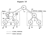
- Figure 16 illustrates a network structure similar to the network structure shown in Figure 4, where a data base function 400 is integrated with the routing number telephone exchange 16. Instead of connecting traffic which shall pass between the local exchanges 10 and 14 via the routing number telephone exchange 16, the data base 400 will redirect the traffic directly to the local exchange 14 when the INITIATE-message is received by the exchange 16. If the call should then be routed to another routing number area, the routing number exchange 16 will accept the request for a signal path to be established and then connect the call to the transit exchange 11 in a traditional fashion, as described with reference to Figure 4.
- routing number telephone exchanges with a data base function in order to apply the principles of the invention. It is also possible to supplement the routing number telephone exchange with a data base function solely within a routing number area in the national network and therewith release the telephone numbers within this area from the geographically fixed local exchanges. Remaining routing number telephone areas within the country will then function traditionally with telephone numbers which are bound to geographically fixed telephone exchanges. Thus, the traffic within the remaining part of the country will be connected in a conventional manner, while in the routing number area 18 "free" telephone numbers will apply in principle, since the redirection of calls will apply within this routing number area 18 as described with reference to Figure 14.
- This method enables the network structure of a country to be extended stepwise to the novel inventive network structure.
- the purpose of the data base 400 is thus to identify the local exchange which controls the B-subscriber.
- a signal path is then connected from local exchange to local exchange in the most optimum manner.
- this procedure is highly beneficial when concerning traffic which requires a large bandwidth and therewith utilize a large part of the network resources.
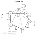
- FIG. 17 illustrates an example of how a connection can be established with the aid of the inventive principles.
- the connection related software 210 in respective telephone exchanges is initiated, this software functioning to establish the desired connection.
- the software 210 use precisely the same signalling procedure as that described above with reference to the handling of services to establish mutual connections.
- the signalling procedure is used in this case to set-up a signal path between those software groups which need to cooperate with one another in the various telephone exchanges in order to establish the desired connection.
- connection-related software 210 must be established between the telephone exchanges 10, 11 and 12 in accordance with Figure 9, a the speech channel passes this way because no direct trunk line 30 is found between the local telephone exchanges 10 and 12 in this particular case.
- Central functions 'similar to those described with reference to Figure 14 can also be used to handle signal. Such central functions, for instance data base-supported functions, are used to indicate connection paths both when the network is intact and when the network is subjected to disturbances and interference.
- Figure 17 illustrates a number of local telephone exchanges 10, 11, 12, 13, 14 which are mutually connected by means of trunk lines 30. As in the earlier case, the A-subscriber 21 in the local telephone exchange 10 wishes to communicate with the B-subscriber 22 in the local telephone exchange 12.
- the data base 500 will normally indicate the first path for setting-up the connection between 21 and 22. However, assume that the trunk line 30-b is subjected to disturbance or interference, for instance as a result of being torn-up by an excavating machine. The data base 500 will then indicate the longer and more expensive second signal path to the local exchange 12, i.e. the path which passes over the local exchanges 13 and 14. The benefit of this arrangement in comparison with conventional telephone networks will be understood from the following.
- the call is first connected to the local exchange 11, where it is discovered that the connection cannot be passed-on because of the break in the trunk line 30-b. Information to this effect must be sent back to the local exchange 10, whereafter the local exchange 10 makes another attempt to establish a connection with the B-subscriber, although now via the local exchanges 13 and 14, all in accordance with fixed routing tables.
- signalling is first effected to the data base 500 and is there then redirected to the local telephone exchange 11 when the network is intact.
- the trunk line 30-b be broken, signalling will be effected from the local exchange 10 to the data base 500, from where it is redirected to the local exchange 13.
- the data base 500 thus keeps an account of the operational state of the trunk connections 30 in a particular area. This enables the connection path of the call to be selected optimally within the area concerned. It may also be that a trunk line between two large towns or cities is heavily loaded and that no further telephone traffic can be allowed on this particular trunk line. In this case, the data base 500 is able to redirect further traffic demands through trunk connections other than the aforesaid most optimum connections, so that traffic can still pass between the two towns. This enables the network resources to be utilized in the most beneficial manner.
- Figure 17 thus illustrates another application of the signalling redirecting principle proposed in accordance with the invention.
- the service-signalling and connection-signalling principles of the invention have been described in the aforegoing with reference to establishing a signal path between two subscribers. Precisely the same mechanism is used generally to establish contact between groups of software in telecommunication exchanges for speech, picture (image) or data transmission, or other telephone network equipment.
- the principles of the invention can be applied to find, for instance, a modem pool, picture processing equipment, speech equipment, etc., in a telecommunication network.
- such equipment need not be found everywhere in the telecommunication network, but only at one or some locations in the network. However, all nodes in the network will have access to this equipment in the manner described above with reference to the redirection of signals.
- the redirection principle can also be applied to establish contact between software in an operations support systems, i.e. a system which assists the telecommunications administration or manager in handling its telephone network and telephone exchange software.
- the operations-support system may, for instance, be used to obtain billing information concerning a given subscriber moving in the network.
- the operations-support system may also be used, for instance, to measure a telephone line from a subscriber who moves in the network. For instance, the subscriber may have logged-in on different telephone sets in the network and perhaps calls and complains of poor speech quality on his particular line. The telephone operator receiving the complaint can then use the aforedescribed signalling mechanism to find the telephone line to which the subscriber is connected at that moment in time.
- signalling will be effected with a dialogue in order to enable such measuring processes to be effected between first software in the telephone operator support system and second software in the telephone exchange in which the line concerned is connected.
- the second software will execute the measuring process and disclose the result with an operation in the dialogue.
- the telephone operator who receives the complaint is thus able to order an investigation of the telephone line concerned and, for instance, subsequently inform the subscriber that there is a fault on that particular line and that a repairman will be sent to put matters right.
- the network when extending or expanding a region by connecting new equipment to the telephone network, it is unnecessary to update the central software with data or information concerning the new equipment in order for the central software to be able to execute operations-support functions on this new equipment.
- the network shall include data base functions which can identify that new equipment has been connected to the network, whereafter the operations-support software is able to control the new equipment, for instance examine, investigate and measure the equipment. It is therefore unnecessary to change or update the operations-support software when equipment is connected to the network.
- the network may include strategically placed measuring equipment for measuring modems in order to check that a modem effects correct conversion of speech and information to digital information. Modems can be distributed on many nodes in a network, although each individual modem can be addressed and controlled with the aid of the single measuring equipment provided.
- Figure 18 is an overview which illustrates division of the signalling into two parts, namely a first service-related signalling procedure 600 and a second connection-related signalling procedure 610.
- the Figure illustrates a telecommunication network in which the nodes 13, 14 and 15 include solely connection-related software, i.e. in which the software is used solely to transfer speech, picture or data connection channels between intelligent local exchanges 10 and 12 which contain both service-related software and connection-related software.
- the protocol 240 is a basic protocol which is able to carry other protocols.
- Figure 19 illustrates the structure of a message 700 which is transported between the signal services handlers 245 and 246.
- the message 700 is comprised of an RDS-head 701 which includes information relating to the signalling service and which can be switched between respective signalling service handlers 245 and 246, and a dialogue operation 702 which can be switched between those software groups (230 and 231 in Figure 12) which utilize the signalling service.
- a greatly simplified description of the types of message present in the basic protocol 240 will be given in the following.
- the signal service that can be configured with the use of other known protocol techniques which, for instance, enable the transmission of several dialogue operations in a message.
- a characteristic feature of the inventive protocol is that it comprises of the messages INITIATE, REDIRECT, BEGIN, END and ABORT.
- a common feature of all of the messages is that the RDS-head includes an address of the telephone exchange to which the message shall be delivered. The precise configuration of this address will depend on the type of underlying signal network used for the signalling process.
- the message INITIATE is used to establish a signal path, in accordance with the aforegoing.
- the RDS-head in the INITIATE-message contains the following information: the identity and the type of the dialogue to be established initially on the signal path and address information which identifies the group of software 220a in Figure 13, and software 230 which initiate the first dialogue.
- Accepted response to the INITIATE-message is REDIRECT, which is used to redirect the establishment of the signal path, END which is used for an individual operation exchange without setting-up a signal path, CONTINUE which is used to accept the establishment of the signal path, ABORT which is used to indicate the occurrence of a fault of some kind, and BEGIN which is used to accept the establishment of a signal path and, at the same time, request counter-directional establishment of a further dialogue prior to responding to the first operation in the initial dialogue.
- the message BEGIN is used to establish a further dialogue on an existing signal path.
- the RDS-head in the BEGIN-message includes the following information: the identity and type of the dialogue to be established on the signal path and address information which identifies software 230 in Figure 13 which initiates the dialogue. If the BEGIN-message is used as a direct response to an INITIATE-message, the head will also contain address information which identifies the group of software 220a in Figure 13 and software 230 which sends the response.
- END An accepted response to the INITIATE-message is END, which is used for an individual operation exchange without establishing dialogue, CONTINUE is used to accept the setting-up of the dialogue, ABORT is used to indicate that an error of some kind has occurred, and BEGIN is used to request a counter-directional setting-up of further dialogue prior to responding to the first operation in the requested dialogue.
- the message REDIRECT is used to redirect the establishment of a signal path to another receiver.
- the RDS-head in the REDIRECT-message contains the same information as the initiate-message which it answers, and in addition an address of the new receiver.
- the message CONTINUE is used to transfer an operation in a dialogue on an existing signal path.
- the RDS-head in the CONTINUE-message contains the following information: the identity of the dialogue with which the message is concerned and address information which identifies the own group of software 220b in Figure 13 and software 232 and also the opposing group of software 220ab in Figure 13 and software 230.
- the message END is used to terminate a dialogue on an existing signal path.
- the RDS-head in the END-message contains the following information: the identity of the dialogue to be terminated and address information which identifies the own group of software 220b in Figure 13 and software 232, and also the opposing group of software 220ab in Figure 13 and software 230.
- the terminated dialogue is the only dialogue to be established along the signal path, the signal path is also dismantled.
- the message ABORT is used to terminate a dialogue on an existing signal path, as a result of the occurrence of a fault.
- the RDS-head in the ABORT-message contains the following information: the identity of the dialogue to be terminated, indication of an abort generated by the user, i.e. by the software 232 or 230 in Figure 13, or an abort generated by the signalling service-related handler 245 or 246 in Figure 13, and address information which identifies the own group of software 220b in Figure 13 and software 232.
- the terminated dialogue was the only dialogue to be established along the signal path, the signal path is also dismantled.
Landscapes
- Engineering & Computer Science (AREA)
- Computer Networks & Wireless Communication (AREA)
- Telephonic Communication Services (AREA)
- Communication Control (AREA)
- Data Exchanges In Wide-Area Networks (AREA)
- Exchange Systems With Centralized Control (AREA)
Claims (6)
- Verfahren zur Signalisierung zwischen Software (210, 220) in verschiedenen Einrichtungen (10, 11, 12) in einem Telekommunikationsnetzwerk,
dadurch gekennzeichnet, dassdas Signalisierungsverfahren über Signalwege (P211, P221) bewirkt wird, die mit Hilfe eines Basisprotokolls (240) eingerichtet wurden;das Basisprotokoll (240) das Einrichten eines Signalweges von Software in einem ersten Geräteteil zu einem zweiten indizierten Geräteteil ermöglicht;das Basisprotokoll (240) es gestattet, den Signalweg von dem zweiten Geräteteil zu einem dritten indizierten Geräteteil umzuleiten;das Basisprotokoll es ermöglicht, dass das Umleiten von dem dritten indizierten Geräteteil zu einem vierten indizierten Geräteteil usw. für eine unbegrenzte Anzahl von Zeiten wiederholt wird;das Umleiten bewirkt werden kann, ohne die Computersoftware in dem ersten indizierten Geräteteil zu beeinflussen;das Basisprotokoll es ermöglicht, dass ein spezielles Teil-Protokoll, welches ein Dialog (241) genannt wird, entlang des Signalweges zwischen Computersoftware in einem ersten Geräteteil und Computersoftware in einem zweiten Geräteteil in dem Telekommunikationsnetzwerk eingerichtet wird; unddass das Basisprotokoll (240) es ermöglicht, dass eine Vielzahl von Dialoge entlang des Signalweges zwischen Software in dem ersten und zweiten Geräteteil eingerichtet werden. - Telekommunikationsnetzwerk zur Ausführung des Signalisierungsverfahrens gemäß Anspruch 1, bei dem das Netzwerk Knotenpunkte (10, 11, 12), Fernleitungen (30) zwischen den Knotenpunkten und ein Signalisierungsnetzwerk (51, 52, 53, 60) zur Signalisierung zwischen den Knotenpunkten aufweist, wobei die Netzknoten Einrichtungen einschließt, wie etwa eine lokale Vermittlungsstelle, ein Modem-Pool, eine Spracheinrichtung, eine Bildverarbeitungseinrichtung, dienstbezogene Software (220) und verbindungsbezogene Software (210),
gekennzeichnet durch
eine Basisprotokollvorrichtung (240) zum Einrichten eines Signalweges von dienstbezogener Software (220A) in einem ersten Geräteteil zu dienstbezogener Software (220B) in einem zweiten indizierten Geräteteil und zum Umleiten
des Signalweges von dem zweiten indizierten Geräteteil zu dienstbezogener Software in einem dritten Geräteteil, und um es zu ermöglichen, dass ein spezielles Teil-Protokoll, welches ein Dialog (241) genannt wird, entlang des Signalweges jeweils zwischen der Computersoftware in dem ersten Geräteteil und dem zweiten und dritten Geräteteil eingerichtet wird, wobei die Basisprotokollvorrichtung es gestattet, dass eine Vielzahl von Dialogen entlang des Signalweges eingerichtet werden. - Telekommunikationsnetzwerk gemäß Anspruch 2,
gekennzeichnet durch
Datenbasen (300, 310, 320, 330), welche Informationen in bezug auf gegenwärtige Teilnehmerverbindungspunkte aufweisen, wobei die Basisprotokollvorrichtung mit den Datenbasen interagiert, um Einrichtungen zu lokalisieren, mit welchen ein gegebener Telefonteilnehmer verbunden ist, um Telekommunikationsdienste zwischen einem ersten Teilnehmer (A) und einem zweiten Teilnehmer (B) einzurichten durch das Einrichten von direkten Signalwegen zwischen Software in einem ersten Geräteteil, welches die Verbindung des ersten Teilnehmers zu dem Netzwerk steuert, und Software in einem zweiten Geräteteil, welches die Verbindung des zweiten Teilnehmers zu dem Netzwerk steuert. - Telekommunikationsnetzwerk gemäß Anspruch 2,
gekennzeichnet durch
Datenbasen, welche Informationen der Positionen von Einrichtungen aufweisen, in welchen eine gegebene Funktion in dem Netzwerk zur Verfügung steht, wobei mit Funktion hier eine Funktion gemeint ist, die mit Software implementiert wird, welche, wenn geeignet, Teile der Einrichtung steuert, wobei die Basisprotokollvorrichtung mit den Datenbasen interagiert, um die gegebenen Funktionen zu lokalisieren. - Telekommunikationsnetzwerk gemäß Anspruch 2,
gekennzeichnet durch
Datenbasen, welche Informationen der Standorte der Teilnehmer und Funktionen in dem Netzwerk aufweisen, wobei die Basisprotokollvorrichtung mit den Datenbasen interagiert, um eine Signalisierung zwischen Software in Einrichtungen in dem Telekommunikationsnetzwerk und Einrichtungen, welche Netzwerkbetreiberoperationen des Telekommunikationsnetzwerkes unterstützen, einzurichten. - Telekommunikationsnetzwerk gemäß Anspruch 2,
dadurch gekennzeichnet, dass
eine begrenzte Anzahl von Geräteteilen in dem Telekommunikationsnetzwerk mit einer Merkmalsfunktionalität in Form von Software ausgerüstet sind, wobei die Merkmalsfunktionalität einer speziellen Teilnehmerkategorie, die Teilnehmerverbindungen für eine gegebene Firma aufweist, einen erweiterten Telekommunikationsdienst zur Verfügung stellt, wobei die Vielzahl der Dialoge es der Merkmalsfunktionalitätssoftware ermöglicht, wechselseitig zu kommunizieren, ohne dass es nötig ist, die Software der verbleibenden Einrichtung in dem Telekommunikationsnetzwerk zu modifizieren.
Applications Claiming Priority (3)
| Application Number | Priority Date | Filing Date | Title |
|---|---|---|---|
| SE9202489 | 1992-08-28 | ||
| SE9202489A SE9202489L (sv) | 1992-08-28 | 1992-08-28 | Nätstruktur och protokoll för telekommunikationsanordning |
| PCT/SE1993/000672 WO1994006251A1 (en) | 1992-08-28 | 1993-08-12 | Network structure and a signalling protocol for a telecommunication network |
Publications (2)
| Publication Number | Publication Date |
|---|---|
| EP0664068A1 EP0664068A1 (de) | 1995-07-26 |
| EP0664068B1 true EP0664068B1 (de) | 2002-10-23 |
Family
ID=20387045
Family Applications (1)
| Application Number | Title | Priority Date | Filing Date |
|---|---|---|---|
| EP93919751A Expired - Lifetime EP0664068B1 (de) | 1992-08-28 | 1993-08-12 | Netzwerkstruktur und signalisierungsprotokoll für ein fernmeldenetz |
Country Status (13)
| Country | Link |
|---|---|
| US (1) | US5517563A (de) |
| EP (1) | EP0664068B1 (de) |
| JP (1) | JPH08500708A (de) |
| KR (1) | KR100323220B1 (de) |
| CN (1) | CN1097970C (de) |
| AU (1) | AU682666B2 (de) |
| BR (1) | BR9306973A (de) |
| CA (1) | CA2141933A1 (de) |
| DE (1) | DE69332437T2 (de) |
| FI (1) | FI950891A (de) |
| MX (1) | MX9305185A (de) |
| SE (1) | SE9202489L (de) |
| WO (1) | WO1994006251A1 (de) |
Families Citing this family (48)
| Publication number | Priority date | Publication date | Assignee | Title |
|---|---|---|---|---|
| SE518247C2 (sv) * | 1992-08-28 | 2002-09-17 | Ericsson Telefon Ab L M | Programvarustruktur för ett telekommunikationssystem |
| DE4341888C1 (de) * | 1993-12-08 | 1995-04-06 | Siemens Ag | Verfahren zum Steuern von Komponenten eines Kommunikationssystems |
| US5657451A (en) * | 1994-01-24 | 1997-08-12 | Telefonaktiebolaget Lm Ericsson | System for determining whether to accept new supplementary services based upon identified types of supplementary service interactions and identified supplementary service interaction criteria |
| CN1131622C (zh) | 1994-05-05 | 2003-12-17 | 斯普林脱通讯有限公司 | 电信控制的方法、系统和装置 |
| SE503022C2 (sv) * | 1994-06-15 | 1996-03-11 | Ericsson Telefon Ab L M | Distribuerad förbindelsestyrning i telekommunikationsnät |
| DE4420886A1 (de) * | 1994-06-15 | 1995-12-21 | Siemens Ag | Kommunikationsvermittlungssystem mit einem Leistungsmerkmalsystem und einem Basisvermittlungssystem |
| US5583914A (en) * | 1994-06-30 | 1996-12-10 | Lucent Technologies Inc. | Intelligent wireless signaling overlay for a telecommunication network |
| SE515179C2 (sv) * | 1994-10-24 | 2001-06-25 | Ericsson Telefon Ab L M | Sätt för internkommunikaton i telekommunikationssystem |
| FI99187C (fi) * | 1994-11-24 | 1997-10-10 | Tecnomen Oy | Menetelmä ja laite älykkäiden toimintojen lisäämiseksi televerkkoon |
| SE504373C2 (sv) * | 1995-04-12 | 1997-01-20 | Telia Ab | Smalbandigt integrerat applikationsnät med multifunktionalitet |
| DE19517574A1 (de) * | 1995-05-12 | 1996-11-14 | Siemens Ag | Verfahren und Einrichtung zur Echokompensatoranschaltung für Fernsprechverbindungen |
| EP0830774B1 (de) * | 1995-06-07 | 2004-10-06 | divine technology ventures | Zugangskontrolle und überwachungssystem für internetserver |
| WO1997000570A1 (en) * | 1995-06-16 | 1997-01-03 | Harris Corporation | Dynamically negotiated application program interface method |
| GB9603582D0 (en) | 1996-02-20 | 1996-04-17 | Hewlett Packard Co | Method of accessing service resource items that are for use in a telecommunications system |
| US5889849A (en) * | 1995-12-19 | 1999-03-30 | Hyundai Electronics Industries Co., Ltd. | Common-channel message conversion method for communication network interface between exchange systems |
| US5737517A (en) * | 1995-12-21 | 1998-04-07 | Ericsson, Inc. | Testing tools in an intelligent network system |
| JPH09214602A (ja) * | 1996-02-02 | 1997-08-15 | Fujitsu Ltd | 加入者系伝送装置における呼制御システム |
| FR2745140B1 (fr) * | 1996-02-15 | 1998-04-24 | Matra Communication | Procede de gestion de signalisation dans un systeme d'autocommutation equipe de bornes radio |
| US5940487A (en) * | 1996-04-10 | 1999-08-17 | Alcatel Usa Sourcing, L.P. | Programmable call processing system and method |
| SE506475C2 (sv) | 1996-04-26 | 1997-12-22 | Ericsson Telefon Ab L M | Tjänste- och förbindelseseparerat nät |
| US5825868A (en) * | 1996-06-04 | 1998-10-20 | Lucent Technologies Inc. | Arrangement for providing private-network line features on central-office-to-PBX trunks |
| US6038309A (en) * | 1996-06-13 | 2000-03-14 | Northern Telecom Limited | Apparatus and method for externally controlling processing of a service call |
| US6028924A (en) * | 1996-06-13 | 2000-02-22 | Northern Telecom Limited | Apparatus and method for controlling processing of a service call |
| US5991389A (en) * | 1996-06-13 | 1999-11-23 | Northern Telecom Limited | Programmable service architecture for call control processing |
| US6243453B1 (en) | 1996-07-17 | 2001-06-05 | Alcatel Usa Sourcing, L.P. | Programmable call processing system and method |
| GB9621248D0 (en) * | 1996-10-11 | 1996-11-27 | Univ Cambridge Tech | Switching system |
| DE59804797D1 (de) * | 1997-01-23 | 2002-08-22 | Siemens Ag | Verfahren zur administrierung zusätzlicher dienste in einem kommunikationsnetz |
| US5999609A (en) * | 1997-04-04 | 1999-12-07 | Sun Microsystems, Inc. | Computer-telephony (CT) system including an electronic call request |
| US6151390A (en) * | 1997-07-31 | 2000-11-21 | Cisco Technology, Inc. | Protocol conversion using channel associated signaling |
| US6967972B1 (en) | 1997-07-31 | 2005-11-22 | Cisco Technology, Inc. | Universal protocol conversion |
| US6111893A (en) * | 1997-07-31 | 2000-08-29 | Cisco Technology, Inc. | Universal protocol conversion |
| US6069947A (en) * | 1997-12-16 | 2000-05-30 | Nortel Networks Corporation | Communication system architecture and operating protocol therefor |
| GB2332590B (en) * | 1997-12-16 | 2002-10-09 | Dsc Telecom Lp | Handling of signalling information within a telecommunications system |
| US6650632B1 (en) | 1998-06-30 | 2003-11-18 | Cisco Technology, Inc. | Feature transparency in a telecommunications network |
| US7212522B1 (en) | 1998-09-30 | 2007-05-01 | Cisco Technology, Inc. | Communicating voice over a packet-switching network |
| US6570869B1 (en) | 1998-09-30 | 2003-05-27 | Cisco Technology, Inc. | Communicating voice over a packet-switching network |
| US6658022B1 (en) | 1998-09-30 | 2003-12-02 | Cisco Technology, Inc. | Signaling protocol for controlling voice calls in a packet switching network |
| EP0991283A1 (de) * | 1998-10-01 | 2000-04-05 | Siemens Aktiengesellschaft | Verfahren zur Behandlung von In-Calls bei IN-Dienstrufnummernportabilität |
| GB2351414A (en) * | 1999-06-22 | 2000-12-27 | Ericsson Telefon Ab L M | Call set-up in a telecommunications network |
| WO2000070885A1 (en) | 1999-05-17 | 2000-11-23 | Telefonaktiebolaget Lm Ericsson (Publ) | Capability negotiation in a telecommunications network |
| US6738343B1 (en) * | 1999-05-26 | 2004-05-18 | Siemens Information & Communication Networks, Inc. | System and method for utilizing direct user signaling to enhance fault tolerant H.323 systems |
| US6693874B1 (en) * | 1999-05-26 | 2004-02-17 | Siemens Information & Communication Networks, Inc. | System and method for enabling fault tolerant H.323 systems |
| US6680952B1 (en) | 1999-06-01 | 2004-01-20 | Cisco Technology, Inc. | Method and apparatus for backhaul of telecommunications signaling protocols over packet-switching networks |
| NO315070B1 (no) * | 2001-01-18 | 2003-06-30 | Ericsson Telefon Ab L M | Forbedringer i tjenesteorienterte nettverk |
| US7945036B1 (en) * | 2003-04-07 | 2011-05-17 | Shoretel, Inc. | Provisioning a phone without involving an administrator |
| US8238538B2 (en) | 2009-05-28 | 2012-08-07 | Comcast Cable Communications, Llc | Stateful home phone service |
| US10594865B2 (en) * | 2018-07-31 | 2020-03-17 | Avaya Inc. | Efficient management of co-existing multi-channel interactions in a contact center |
| US10681213B2 (en) * | 2018-07-31 | 2020-06-09 | Avaya Inc. | Dynamic synchronization of co-existing multichannel interactions in a contact center |
Family Cites Families (7)
| Publication number | Priority date | Publication date | Assignee | Title |
|---|---|---|---|---|
| US4455455A (en) * | 1982-12-01 | 1984-06-19 | Gte Business Communication Systems Inc. | Internodal conference call administrator |
| US4464543A (en) * | 1982-12-01 | 1984-08-07 | Gte Business Communication Systems Inc. | Network control center call trace |
| US4674115A (en) * | 1985-09-20 | 1987-06-16 | Jabil Circuit Company | Programmable telephone switcher |
| US5113499A (en) * | 1989-04-28 | 1992-05-12 | Sprint International Communications Corp. | Telecommunication access management system for a packet switching network |
| US4924500A (en) * | 1989-05-17 | 1990-05-08 | Northern Telecom Limited | Carrier independent network services |
| US5008930A (en) * | 1989-10-24 | 1991-04-16 | At&T Bell Laboratories | Customer definable integrated voice/data call transfer technique |
| US5048081A (en) * | 1989-12-28 | 1991-09-10 | At&T Bell Laboratories | Arrangement for routing packetized messages |
-
1992
- 1992-08-28 SE SE9202489A patent/SE9202489L/ not_active Application Discontinuation
-
1993
- 1993-08-12 AU AU49885/93A patent/AU682666B2/en not_active Ceased
- 1993-08-12 EP EP93919751A patent/EP0664068B1/de not_active Expired - Lifetime
- 1993-08-12 DE DE69332437T patent/DE69332437T2/de not_active Expired - Lifetime
- 1993-08-12 JP JP6507108A patent/JPH08500708A/ja active Pending
- 1993-08-12 BR BR9306973A patent/BR9306973A/pt not_active IP Right Cessation
- 1993-08-12 WO PCT/SE1993/000672 patent/WO1994006251A1/en active IP Right Grant
- 1993-08-12 CA CA002141933A patent/CA2141933A1/en not_active Abandoned
- 1993-08-12 KR KR1019950700855A patent/KR100323220B1/ko not_active IP Right Cessation
- 1993-08-26 MX MX9305185A patent/MX9305185A/es not_active IP Right Cessation
- 1993-08-27 US US08/112,537 patent/US5517563A/en not_active Expired - Lifetime
- 1993-08-27 CN CN93116906A patent/CN1097970C/zh not_active Expired - Lifetime
-
1995
- 1995-02-27 FI FI950891A patent/FI950891A/fi unknown
Also Published As
| Publication number | Publication date |
|---|---|
| CA2141933A1 (en) | 1994-03-17 |
| EP0664068A1 (de) | 1995-07-26 |
| BR9306973A (pt) | 1999-01-12 |
| SE9202489D0 (sv) | 1992-08-28 |
| US5517563A (en) | 1996-05-14 |
| KR950703262A (ko) | 1995-08-23 |
| JPH08500708A (ja) | 1996-01-23 |
| MX9305185A (es) | 1994-06-30 |
| FI950891A0 (fi) | 1995-02-27 |
| DE69332437T2 (de) | 2003-03-20 |
| CN1084001A (zh) | 1994-03-16 |
| CN1097970C (zh) | 2003-01-01 |
| KR100323220B1 (ko) | 2002-06-27 |
| DE69332437D1 (de) | 2002-11-28 |
| WO1994006251A1 (en) | 1994-03-17 |
| FI950891A (fi) | 1995-02-27 |
| AU682666B2 (en) | 1997-10-16 |
| SE9202489L (sv) | 1994-03-01 |
| AU4988593A (en) | 1994-03-29 |
Similar Documents
| Publication | Publication Date | Title |
|---|---|---|
| EP0664068B1 (de) | Netzwerkstruktur und signalisierungsprotokoll für ein fernmeldenetz | |
| EP0660572B1 (de) | Eingehender Faxdienst abhängig vom Ort eines schnurlosen Telefons | |
| CA2195495C (en) | Control of telecommunications networks | |
| US5416834A (en) | Redirection of calls by a communication terminal | |
| EP0627146B1 (de) | Herstellungsverfahren einer nachrichtenverbindung und system zur realisierung dieses verfahrens | |
| US5850434A (en) | Telecommunications network | |
| EP0493914B1 (de) | Transparente Signalisierung für entfernte Endgeräte | |
| US5598458A (en) | Telecommunication switching system having transparent wireless features | |
| US5848145A (en) | Automatic learning of network routing using random routes | |
| CA2107754C (en) | Shared line appearance across a plurality of switching systems | |
| US5553128A (en) | Control of call forwarding by a target telephone | |
| AU668918B2 (en) | A method of establishing cooperation with a functionality | |
| CA2008905C (en) | Arrangement for providing a call-connection service | |
| US6363142B1 (en) | Network directed call pickup service | |
| US6493337B1 (en) | Method and apparatus for internet access which bypass local central end office using digital loop carrier and permanent signal treatment procedures | |
| US20050100155A1 (en) | Call distribution in distributed call centers | |
| US5644632A (en) | Distributed key telephone station network | |
| JPH118694A (ja) | 仮想アクセスネットワーク機能を有する交換機および交換システム | |
| EP0766898B1 (de) | Verbindungsaufbau und dienstanruf in fernsprechnetzen | |
| US6341126B1 (en) | Inhomogeneous connections | |
| EP0748133B1 (de) | Verfahren zum Telekommunikationsnetzbetrieb und Netzwerk dafür | |
| EP1025714B1 (de) | Fernsprechanrufverarbeitungssystem | |
| US6965595B2 (en) | Method and apparatus for internet access which bypass local central end office using digital loop carrier and permanent signal treatment procedures | |
| KR20010045647A (ko) | 교환 시스템에서 출중계호에 대한 지능망 처리 방법 | |
| JPS6399695A (ja) | 自動電話交換網における網内呼接続制御方式 |
Legal Events
| Date | Code | Title | Description |
|---|---|---|---|
| PUAI | Public reference made under article 153(3) epc to a published international application that has entered the european phase |
Free format text: ORIGINAL CODE: 0009012 |
|
| 17P | Request for examination filed |
Effective date: 19950215 |
|
| AK | Designated contracting states |
Kind code of ref document: A1 Designated state(s): BE CH DE DK ES FR GB GR IE IT LI NL |
|
| 17Q | First examination report despatched |
Effective date: 20000121 |
|
| GRAG | Despatch of communication of intention to grant |
Free format text: ORIGINAL CODE: EPIDOS AGRA |
|
| GRAG | Despatch of communication of intention to grant |
Free format text: ORIGINAL CODE: EPIDOS AGRA |
|
| GRAH | Despatch of communication of intention to grant a patent |
Free format text: ORIGINAL CODE: EPIDOS IGRA |
|
| GRAH | Despatch of communication of intention to grant a patent |
Free format text: ORIGINAL CODE: EPIDOS IGRA |
|
| GRAA | (expected) grant |
Free format text: ORIGINAL CODE: 0009210 |
|
| AK | Designated contracting states |
Kind code of ref document: B1 Designated state(s): BE CH DE DK ES FR GB GR IE IT LI NL |
|
| PG25 | Lapsed in a contracting state [announced via postgrant information from national office to epo] |
Ref country code: NL Free format text: LAPSE BECAUSE OF FAILURE TO SUBMIT A TRANSLATION OF THE DESCRIPTION OR TO PAY THE FEE WITHIN THE PRESCRIBED TIME-LIMIT Effective date: 20021023 Ref country code: LI Free format text: LAPSE BECAUSE OF FAILURE TO SUBMIT A TRANSLATION OF THE DESCRIPTION OR TO PAY THE FEE WITHIN THE PRESCRIBED TIME-LIMIT Effective date: 20021023 Ref country code: IT Free format text: LAPSE BECAUSE OF FAILURE TO SUBMIT A TRANSLATION OF THE DESCRIPTION OR TO PAY THE FEE WITHIN THE PRESCRIBED TIME-LIMIT;WARNING: LAPSES OF ITALIAN PATENTS WITH EFFECTIVE DATE BEFORE 2007 MAY HAVE OCCURRED AT ANY TIME BEFORE 2007. THE CORRECT EFFECTIVE DATE MAY BE DIFFERENT FROM THE ONE RECORDED. Effective date: 20021023 Ref country code: GR Free format text: LAPSE BECAUSE OF FAILURE TO SUBMIT A TRANSLATION OF THE DESCRIPTION OR TO PAY THE FEE WITHIN THE PRESCRIBED TIME-LIMIT Effective date: 20021023 Ref country code: FR Free format text: LAPSE BECAUSE OF FAILURE TO SUBMIT A TRANSLATION OF THE DESCRIPTION OR TO PAY THE FEE WITHIN THE PRESCRIBED TIME-LIMIT Effective date: 20021023 Ref country code: CH Free format text: LAPSE BECAUSE OF FAILURE TO SUBMIT A TRANSLATION OF THE DESCRIPTION OR TO PAY THE FEE WITHIN THE PRESCRIBED TIME-LIMIT Effective date: 20021023 Ref country code: BE Free format text: LAPSE BECAUSE OF FAILURE TO SUBMIT A TRANSLATION OF THE DESCRIPTION OR TO PAY THE FEE WITHIN THE PRESCRIBED TIME-LIMIT Effective date: 20021023 |
|
| REG | Reference to a national code |
Ref country code: GB Ref legal event code: FG4D |
|
| REG | Reference to a national code |
Ref country code: CH Ref legal event code: EP |
|
| REG | Reference to a national code |
Ref country code: IE Ref legal event code: FG4D |
|
| REF | Corresponds to: |
Ref document number: 69332437 Country of ref document: DE Date of ref document: 20021128 |
|
| PG25 | Lapsed in a contracting state [announced via postgrant information from national office to epo] |
Ref country code: DK Free format text: LAPSE BECAUSE OF FAILURE TO SUBMIT A TRANSLATION OF THE DESCRIPTION OR TO PAY THE FEE WITHIN THE PRESCRIBED TIME-LIMIT Effective date: 20030123 |
|
| NLV1 | Nl: lapsed or annulled due to failure to fulfill the requirements of art. 29p and 29m of the patents act | ||
| PG25 | Lapsed in a contracting state [announced via postgrant information from national office to epo] |
Ref country code: ES Free format text: LAPSE BECAUSE OF FAILURE TO SUBMIT A TRANSLATION OF THE DESCRIPTION OR TO PAY THE FEE WITHIN THE PRESCRIBED TIME-LIMIT Effective date: 20030429 |
|
| REG | Reference to a national code |
Ref country code: CH Ref legal event code: PL |
|
| PG25 | Lapsed in a contracting state [announced via postgrant information from national office to epo] |
Ref country code: IE Free format text: LAPSE BECAUSE OF NON-PAYMENT OF DUE FEES Effective date: 20030812 Ref country code: GB Free format text: LAPSE BECAUSE OF NON-PAYMENT OF DUE FEES Effective date: 20030812 |
|
| EN | Fr: translation not filed | ||
| PLBE | No opposition filed within time limit |
Free format text: ORIGINAL CODE: 0009261 |
|
| STAA | Information on the status of an ep patent application or granted ep patent |
Free format text: STATUS: NO OPPOSITION FILED WITHIN TIME LIMIT |
|
| 26N | No opposition filed |
Effective date: 20030724 |
|
| GBPC | Gb: european patent ceased through non-payment of renewal fee |
Effective date: 20030812 |
|
| REG | Reference to a national code |
Ref country code: IE Ref legal event code: MM4A |
|
| PGFP | Annual fee paid to national office [announced via postgrant information from national office to epo] |
Ref country code: DE Payment date: 20120829 Year of fee payment: 20 |
|
| REG | Reference to a national code |
Ref country code: DE Ref legal event code: R071 Ref document number: 69332437 Country of ref document: DE |
|
| PG25 | Lapsed in a contracting state [announced via postgrant information from national office to epo] |
Ref country code: DE Free format text: LAPSE BECAUSE OF EXPIRATION OF PROTECTION Effective date: 20130813 |