EP0662438A1 - Vorrichtung zum kontinuierlichen Zuführen eines Bandes zu einer bandverarbeitenden Einrichtung - Google Patents
Vorrichtung zum kontinuierlichen Zuführen eines Bandes zu einer bandverarbeitenden Einrichtung Download PDFInfo
- Publication number
- EP0662438A1 EP0662438A1 EP19940120058 EP94120058A EP0662438A1 EP 0662438 A1 EP0662438 A1 EP 0662438A1 EP 19940120058 EP19940120058 EP 19940120058 EP 94120058 A EP94120058 A EP 94120058A EP 0662438 A1 EP0662438 A1 EP 0662438A1
- Authority
- EP
- European Patent Office
- Prior art keywords
- tape
- supply roll
- belt
- band
- smoothing
- Prior art date
- Legal status (The legal status is an assumption and is not a legal conclusion. Google has not performed a legal analysis and makes no representation as to the accuracy of the status listed.)
- Withdrawn
Links
Images


Classifications
-
- B—PERFORMING OPERATIONS; TRANSPORTING
- B29—WORKING OF PLASTICS; WORKING OF SUBSTANCES IN A PLASTIC STATE IN GENERAL
- B29C—SHAPING OR JOINING OF PLASTICS; SHAPING OF MATERIAL IN A PLASTIC STATE, NOT OTHERWISE PROVIDED FOR; AFTER-TREATMENT OF THE SHAPED PRODUCTS, e.g. REPAIRING
- B29C66/00—General aspects of processes or apparatus for joining preformed parts
- B29C66/40—General aspects of joining substantially flat articles, e.g. plates, sheets or web-like materials; Making flat seams in tubular or hollow articles; Joining single elements to substantially flat surfaces
- B29C66/41—Joining substantially flat articles ; Making flat seams in tubular or hollow articles
- B29C66/43—Joining a relatively small portion of the surface of said articles
-
- B—PERFORMING OPERATIONS; TRANSPORTING
- B29—WORKING OF PLASTICS; WORKING OF SUBSTANCES IN A PLASTIC STATE IN GENERAL
- B29C—SHAPING OR JOINING OF PLASTICS; SHAPING OF MATERIAL IN A PLASTIC STATE, NOT OTHERWISE PROVIDED FOR; AFTER-TREATMENT OF THE SHAPED PRODUCTS, e.g. REPAIRING
- B29C65/00—Joining or sealing of preformed parts, e.g. welding of plastics materials; Apparatus therefor
- B29C65/02—Joining or sealing of preformed parts, e.g. welding of plastics materials; Apparatus therefor by heating, with or without pressure
- B29C65/06—Joining or sealing of preformed parts, e.g. welding of plastics materials; Apparatus therefor by heating, with or without pressure using friction, e.g. spin welding
-
- B—PERFORMING OPERATIONS; TRANSPORTING
- B29—WORKING OF PLASTICS; WORKING OF SUBSTANCES IN A PLASTIC STATE IN GENERAL
- B29C—SHAPING OR JOINING OF PLASTICS; SHAPING OF MATERIAL IN A PLASTIC STATE, NOT OTHERWISE PROVIDED FOR; AFTER-TREATMENT OF THE SHAPED PRODUCTS, e.g. REPAIRING
- B29C65/00—Joining or sealing of preformed parts, e.g. welding of plastics materials; Apparatus therefor
- B29C65/74—Joining or sealing of preformed parts, e.g. welding of plastics materials; Apparatus therefor by welding and severing, or by joining and severing, the severing being performed in the area to be joined, next to the area to be joined, in the joint area or next to the joint area
- B29C65/745—Joining or sealing of preformed parts, e.g. welding of plastics materials; Apparatus therefor by welding and severing, or by joining and severing, the severing being performed in the area to be joined, next to the area to be joined, in the joint area or next to the joint area using a single unit having both a severing tool and a welding tool
- B29C65/7451—Joining or sealing of preformed parts, e.g. welding of plastics materials; Apparatus therefor by welding and severing, or by joining and severing, the severing being performed in the area to be joined, next to the area to be joined, in the joint area or next to the joint area using a single unit having both a severing tool and a welding tool the severing tool and the welding tool being movable with respect to one-another
-
- B—PERFORMING OPERATIONS; TRANSPORTING
- B29—WORKING OF PLASTICS; WORKING OF SUBSTANCES IN A PLASTIC STATE IN GENERAL
- B29C—SHAPING OR JOINING OF PLASTICS; SHAPING OF MATERIAL IN A PLASTIC STATE, NOT OTHERWISE PROVIDED FOR; AFTER-TREATMENT OF THE SHAPED PRODUCTS, e.g. REPAIRING
- B29C66/00—General aspects of processes or apparatus for joining preformed parts
- B29C66/70—General aspects of processes or apparatus for joining preformed parts characterised by the composition, physical properties or the structure of the material of the parts to be joined; Joining with non-plastics material
- B29C66/73—General aspects of processes or apparatus for joining preformed parts characterised by the composition, physical properties or the structure of the material of the parts to be joined; Joining with non-plastics material characterised by the intensive physical properties of the material of the parts to be joined, by the optical properties of the material of the parts to be joined, by the extensive physical properties of the parts to be joined, by the state of the material of the parts to be joined or by the material of the parts to be joined being a thermoplastic or a thermoset
- B29C66/739—General aspects of processes or apparatus for joining preformed parts characterised by the composition, physical properties or the structure of the material of the parts to be joined; Joining with non-plastics material characterised by the intensive physical properties of the material of the parts to be joined, by the optical properties of the material of the parts to be joined, by the extensive physical properties of the parts to be joined, by the state of the material of the parts to be joined or by the material of the parts to be joined being a thermoplastic or a thermoset characterised by the material of the parts to be joined being a thermoplastic or a thermoset
- B29C66/7392—General aspects of processes or apparatus for joining preformed parts characterised by the composition, physical properties or the structure of the material of the parts to be joined; Joining with non-plastics material characterised by the intensive physical properties of the material of the parts to be joined, by the optical properties of the material of the parts to be joined, by the extensive physical properties of the parts to be joined, by the state of the material of the parts to be joined or by the material of the parts to be joined being a thermoplastic or a thermoset characterised by the material of the parts to be joined being a thermoplastic or a thermoset characterised by the material of at least one of the parts being a thermoplastic
- B29C66/73921—General aspects of processes or apparatus for joining preformed parts characterised by the composition, physical properties or the structure of the material of the parts to be joined; Joining with non-plastics material characterised by the intensive physical properties of the material of the parts to be joined, by the optical properties of the material of the parts to be joined, by the extensive physical properties of the parts to be joined, by the state of the material of the parts to be joined or by the material of the parts to be joined being a thermoplastic or a thermoset characterised by the material of the parts to be joined being a thermoplastic or a thermoset characterised by the material of at least one of the parts being a thermoplastic characterised by the materials of both parts being thermoplastics
-
- B—PERFORMING OPERATIONS; TRANSPORTING
- B29—WORKING OF PLASTICS; WORKING OF SUBSTANCES IN A PLASTIC STATE IN GENERAL
- B29C—SHAPING OR JOINING OF PLASTICS; SHAPING OF MATERIAL IN A PLASTIC STATE, NOT OTHERWISE PROVIDED FOR; AFTER-TREATMENT OF THE SHAPED PRODUCTS, e.g. REPAIRING
- B29C66/00—General aspects of processes or apparatus for joining preformed parts
- B29C66/80—General aspects of machine operations or constructions and parts thereof
- B29C66/82—Pressure application arrangements, e.g. transmission or actuating mechanisms for joining tools or clamps
- B29C66/822—Transmission mechanisms
- B29C66/8221—Scissor or lever mechanisms, i.e. involving a pivot point
-
- B—PERFORMING OPERATIONS; TRANSPORTING
- B29—WORKING OF PLASTICS; WORKING OF SUBSTANCES IN A PLASTIC STATE IN GENERAL
- B29C—SHAPING OR JOINING OF PLASTICS; SHAPING OF MATERIAL IN A PLASTIC STATE, NOT OTHERWISE PROVIDED FOR; AFTER-TREATMENT OF THE SHAPED PRODUCTS, e.g. REPAIRING
- B29C66/00—General aspects of processes or apparatus for joining preformed parts
- B29C66/80—General aspects of machine operations or constructions and parts thereof
- B29C66/82—Pressure application arrangements, e.g. transmission or actuating mechanisms for joining tools or clamps
- B29C66/822—Transmission mechanisms
- B29C66/8225—Crank mechanisms
-
- B—PERFORMING OPERATIONS; TRANSPORTING
- B29—WORKING OF PLASTICS; WORKING OF SUBSTANCES IN A PLASTIC STATE IN GENERAL
- B29C—SHAPING OR JOINING OF PLASTICS; SHAPING OF MATERIAL IN A PLASTIC STATE, NOT OTHERWISE PROVIDED FOR; AFTER-TREATMENT OF THE SHAPED PRODUCTS, e.g. REPAIRING
- B29C66/00—General aspects of processes or apparatus for joining preformed parts
- B29C66/80—General aspects of machine operations or constructions and parts thereof
- B29C66/83—General aspects of machine operations or constructions and parts thereof characterised by the movement of the joining or pressing tools
- B29C66/832—Reciprocating joining or pressing tools
- B29C66/8322—Joining or pressing tools reciprocating along one axis
-
- B—PERFORMING OPERATIONS; TRANSPORTING
- B65—CONVEYING; PACKING; STORING; HANDLING THIN OR FILAMENTARY MATERIAL
- B65H—HANDLING THIN OR FILAMENTARY MATERIAL, e.g. SHEETS, WEBS, CABLES
- B65H19/00—Changing the web roll
- B65H19/10—Changing the web roll in unwinding mechanisms or in connection with unwinding operations
- B65H19/14—Accumulating surplus web for advancing to machine while changing the web roll
-
- B—PERFORMING OPERATIONS; TRANSPORTING
- B65—CONVEYING; PACKING; STORING; HANDLING THIN OR FILAMENTARY MATERIAL
- B65H—HANDLING THIN OR FILAMENTARY MATERIAL, e.g. SHEETS, WEBS, CABLES
- B65H19/00—Changing the web roll
- B65H19/10—Changing the web roll in unwinding mechanisms or in connection with unwinding operations
- B65H19/18—Attaching, e.g. pasting, the replacement web to the expiring web
- B65H19/1842—Attaching, e.g. pasting, the replacement web to the expiring web standing splicing, i.e. the expiring web being stationary during splicing contact
- B65H19/1852—Attaching, e.g. pasting, the replacement web to the expiring web standing splicing, i.e. the expiring web being stationary during splicing contact taking place at a distance from the replacement roll
-
- B—PERFORMING OPERATIONS; TRANSPORTING
- B65—CONVEYING; PACKING; STORING; HANDLING THIN OR FILAMENTARY MATERIAL
- B65H—HANDLING THIN OR FILAMENTARY MATERIAL, e.g. SHEETS, WEBS, CABLES
- B65H19/00—Changing the web roll
- B65H19/10—Changing the web roll in unwinding mechanisms or in connection with unwinding operations
- B65H19/18—Attaching, e.g. pasting, the replacement web to the expiring web
- B65H19/1857—Support arrangement of web rolls
- B65H19/1873—Support arrangement of web rolls with two stationary roll supports carrying alternately the replacement and the expiring roll
-
- B—PERFORMING OPERATIONS; TRANSPORTING
- B29—WORKING OF PLASTICS; WORKING OF SUBSTANCES IN A PLASTIC STATE IN GENERAL
- B29C—SHAPING OR JOINING OF PLASTICS; SHAPING OF MATERIAL IN A PLASTIC STATE, NOT OTHERWISE PROVIDED FOR; AFTER-TREATMENT OF THE SHAPED PRODUCTS, e.g. REPAIRING
- B29C66/00—General aspects of processes or apparatus for joining preformed parts
- B29C66/01—General aspects dealing with the joint area or with the area to be joined
- B29C66/05—Particular design of joint configurations
- B29C66/10—Particular design of joint configurations particular design of the joint cross-sections
- B29C66/11—Joint cross-sections comprising a single joint-segment, i.e. one of the parts to be joined comprising a single joint-segment in the joint cross-section
- B29C66/112—Single lapped joints
- B29C66/1122—Single lap to lap joints, i.e. overlap joints
-
- B—PERFORMING OPERATIONS; TRANSPORTING
- B65—CONVEYING; PACKING; STORING; HANDLING THIN OR FILAMENTARY MATERIAL
- B65H—HANDLING THIN OR FILAMENTARY MATERIAL, e.g. SHEETS, WEBS, CABLES
- B65H2301/00—Handling processes for sheets or webs
- B65H2301/40—Type of handling process
- B65H2301/46—Splicing
- B65H2301/461—Processing webs in splicing process
- B65H2301/4613—Processing webs in splicing process during splicing
- B65H2301/46132—Processing webs in splicing process during splicing consuming web up to trailing edge
-
- B—PERFORMING OPERATIONS; TRANSPORTING
- B65—CONVEYING; PACKING; STORING; HANDLING THIN OR FILAMENTARY MATERIAL
- B65H—HANDLING THIN OR FILAMENTARY MATERIAL, e.g. SHEETS, WEBS, CABLES
- B65H2301/00—Handling processes for sheets or webs
- B65H2301/40—Type of handling process
- B65H2301/46—Splicing
- B65H2301/461—Processing webs in splicing process
- B65H2301/4615—Processing webs in splicing process after splicing
- B65H2301/4617—Processing webs in splicing process after splicing cutting webs in splicing process
- B65H2301/46172—Processing webs in splicing process after splicing cutting webs in splicing process cutting expiring web only
-
- B—PERFORMING OPERATIONS; TRANSPORTING
- B65—CONVEYING; PACKING; STORING; HANDLING THIN OR FILAMENTARY MATERIAL
- B65H—HANDLING THIN OR FILAMENTARY MATERIAL, e.g. SHEETS, WEBS, CABLES
- B65H2301/00—Handling processes for sheets or webs
- B65H2301/40—Type of handling process
- B65H2301/46—Splicing
- B65H2301/463—Splicing splicing means, i.e. means by which a web end is bound to another web end
- B65H2301/4634—Heat seal splice
Definitions
- the invention relates to a device for continuously feeding a tape, in particular a plastic tape from a supply to a tape processing device, in particular to a tape strapping device, with a first supply roll and a second supply roll, of which the beginning of the tape is fed to the one supply roll of a tape feed device as soon as that The end of the other supply roll is reached.
- strap processing devices for example strapping devices for packages
- only a limited amount of strap can be made available on a supply roll.
- this tape supply is exhausted, a new supply roll must be provided and it is necessary to feed the tape start of this new roll to the tape processing device the moment the tape of the previous roll ends. It is difficult to find the right moment here, and the operator has to keep an eye on the end of the supply roll and must always be available at the right moment to insert the new roll in time.
- the object of the invention is to avoid this disadvantage and to provide a device with which the tape change takes place automatically and no disturbances occur when inserting a new tape.
- a connecting device for connecting the tape end of one supply roll to the tape start of the other supply roll, a clamping device for inserting, holding and providing a tape start for the connecting device, a calibration device for calibrating and smoothing the tape connection point and a tape storage device is provided, which is connected downstream of the connecting device and the calibration device and from which the tape is fed to the tape processing device.
- This configuration has the advantage that the respective replacement roll can be provided regardless of how far the tape has run from the first supply roll.
- a sensor with a switching device which detects the end of a supply roll and activates the connecting device, is expediently arranged in the direction of movement of the belt at a distance from the connecting device.
- a transport device with a tape clamp is expediently arranged between the calibration device and the tape storage device, which holds the tape at a distance from its tape end and pulls the finished tape joint through the calibration device, where the joint is at its edges trimmed and smoothed.
- the connecting device can be a welding device which connects the end of the band of one supply roll to the beginning of the band of the other supply roll by pressure and heat.
- a welding device can be used to connect steel strips or plastic strips.
- a friction welding device is expediently used, which has a knife for cutting off the tape end and a friction jaw for moving the tape end of the one supply roll under pressure on the beginning of the tape of the other supply roll to generate frictional heat between the contact surfaces and tapes made of thermosensitive material having. If such a connecting device is activated by the sensor that detects the end of a supply reel, the descending friction stamp first cuts off the end of the supply that is still behind it, while simultaneously laying down on the start of the second supply reel and holding it.
- the vibrator of the friction welding device then moves the end of the strip back and forth on the start of the new supply roll, thereby generating frictional heat that softens the strips on their superimposed surfaces, where they then connect to one another by pressing together as soon as the frictional movement stops.
- the calibration device for the connection point has at least one smoothing surface for smoothing the strip surface in the area of the connection point and two knives for smoothing the strip edges in the area of the connection point.
- the calibration device can have a rotating driven smoothing roller, which carries an abrasive on its circumference and is provided with knife edges at its edges. These knife edges can form, for example, the peripheral edge of circular knives which are arranged on the end faces of the smoothing roll.
- the smoothing roll can be moved back and forth in the path of movement of the belt and with one Counter pressure surface cooperates over which the tape is pulled.
- the smoothing roll can be pivoted into the path of movement of the belt with the aid of an air cylinder as soon as the connection point has been established and the belt is pulled by a transport device in the longitudinal direction under the smoothing roll.
- a slide movable by a drive in the longitudinal direction of the belt is expediently provided, which has a belt channel in which the belt can be clamped with the belt clamp.
- the clamping device with which the beginning of the tape of the new supply roll is held until the connecting device is activated when the end of the tape passes the sensor, can be swung out of the path of movement of the tape, so that the operator can easily insert the beginning of a new roll into the clamping device.
- the clamping device is then pivoted back into the movement path of the belt, a clamping drive clamping the beginning of the belt in the clamping device.
- This clamping drive is released as soon as a knife has cut off the rear end of the supply roll and the connection between the beginning and end of the band has been established.
- the connecting device simultaneously releases the locking of the clamping device, so that it automatically swings forward as soon as the straps are connected.
- 10 denotes a strap unwinding and feeding device with which a strapping strap - hereinafter referred to simply as "strap" 11 - made of thermosensitive plastic, for example made of polypropylene, is fed to a strapping station (not shown) for packages.
- strap a strapping strap - hereinafter referred to simply as "strap" 11 - made of thermosensitive plastic, for example made of polypropylene, is fed to a strapping station (not shown) for packages.
- the tape unwinding and feeding device consists of a base frame 12 on which a climbing column 13 with a tape storage device 14, 15 and a bearing frame 16 are arranged.
- the bearing frame 16 has a table top 17 which is supported by three pairs of posts 18, 19 and 20, which are laterally stiffened by trusses and struts (not shown here).
- a first supply roll 21 is rotatably mounted on the posts 18 and a second supply roll 22 is rotatably mounted on the posts 19.
- a considerable length of tape 11a and 11b is wound on each supply roll 21 and 22, which is fed to the tape storage device 14 and 15 and from there to the strapping station via a plurality of deflection rolls 24a, 24b, 25, 26 and 27, as indicated by the arrow 28 is.
- Each supply roll 21, 22 has a brake 29 or 30, which prevents the supply roll rotates at a higher speed than the tape take-off speed.
- the tape storage device consists of a roller block 15 fixedly arranged at the upper end of the climbing column 13 with a plurality of rollers 32 which are freely rotatably mounted on a common, fixed axis 31, and of a movable roller block 14 which is vertically displaceably mounted on the lower end of the climbing column 13 and which is mounted on one the climbing column 13 vertically displaceable axis 33 carries freely rotatable rollers 34.
- the tape 11 drawn off the tape unwinding and feeding device 10 is guided eight times over the rollers 32 and 34 of the roller blocks 15 and 14 and is fed from the upper roller block 15 out of the tape processing device.
- the movable roller block 14 can move upward on the climbing column 13 when the tape 11 is held in the tape unwinding and feeding device 10 and no tape is running into the tape storage device.
- the tape unwinding and feeding device 10 shown in the drawings is provided with a connecting device 35, a clamping device 36, a calibration device 37 and a transport device 38, which are arranged in a suitable manner on or under the table top 17.
- a sensor 40 with a switching device is arranged on the column 20 between the deflecting rollers 24a and 24b on the one hand and 25 and 26 on the other hand, which sensor senses the tape end of the first supply roll 21 or the second supply roll 22 running past it and turns on the connector 35.
- the connecting device 35 is a friction welding device known per se, as is usually used for connecting the ends of a strap.
- This friction welding device has a reciprocating friction jaw 42 which is pivoted back and forth via an eccentric 43 by a motor 44 transversely to the longitudinal direction of the strip, while it is pressed by a pressure stamp 45 with the upper end of the strip 11b onto a lower beginning 11a of the strip. Due to the frictional heat generated the thermoplastic plastic strips are heated on their surface and welded together as soon as the friction jaw 42 comes to a standstill.
- the calibration device 37 arranged behind the connecting device in the direction of movement 39 essentially consists of a smoothing roller 49 which is rotatably driven by a motor 48, which is mounted on a triangular rocker arm 50 and is pivoted down by a pneumatic cylinder 51 onto a counter pressure surface 52 in the path of movement of the belt 11 can.
- the smoothing roller 49 carries on its circumference an abrasive 53 and on its two end faces circular knives 54 and 55 which, with their edges 56 and 57 projecting beyond the outer circumference of the smoothing roller, form knife edges.
- the transport device 38 is arranged in the direction of movement 39 behind the calibration device 37 and in front of the last deflection roller 27.
- This consists of a carriage 58 which can be displaced in the longitudinal direction of the belt on the table 17 and has an upwardly open belt channel 59 through which the belt 11 runs and on the bottom 60 of which the belt can be clamped with a belt clamp 61.
- the band clamp 61 is a so-called "frog clamp” which is self-clamping against the direction of movement 39 of the band 11 and is articulated at the end of the piston rod 62 of a pneumatic drive cylinder 63 which holds the band clamp 61 and with it the band 11 clamped in the band channel 59 together with the carriage 58 can slide in the direction of movement 39.
- the clamping device 36 is arranged below the table top 17 and can be swiveled forward out of the path of movement of the belt 11 about a horizontal axis 65 (FIG. 4).
- the clamping device 36 has a band passage 67 which is open on its rear side 66 and which is delimited on the upper side by a clamping plate 68 which is pulled down by a pneumatic clamp drive cylinder 69 onto the band inserted into the band passage 67 and clamps it.
- a pawl 70 engages in a detent 71 provided for this purpose on the drive cylinder 69 and holds the clamping device 36 in its vertical ready position, in which the beginning of the band 11a is in the path of movement of the band 11.
- this pawl 70 is lifted out of the detent 71 by an actuating element (not shown in detail) arranged on the connecting device 35, the drive cylinder 69 simultaneously releasing the clamping plate 68.
- a spring 72 engaging the clamp drive cylinder 69 then pivots the clamp device 36 to the front, the band beginning 11a now held by the spring-loaded holding stamp 47 of the connecting device 35 emerging from the band passage 67 of the clamp device 36 to the rear.
- the device works as follows: As long as the second supply roll 22 contains a sufficient amount of tape, the tape 11 is pulled off in the direction of arrow 28 from the tape storage device 14, 15. The lower, movable roller block 14 is in its lowest position shown in FIG. 1 and the belt 11 runs around all rollers 32 and 34 of the roller blocks 14 and 15, whereby it is fed to the upper roller block and unhindered by the second supply roller 22 is subtracted. It runs around the deflection rollers 24b, 26 and 27, while the connecting device 35, the calibration device 37 and the transport device 38 are in their ineffective positions.
- the operator can place a full, first supply roll 21 on its axis in the bearing frame 16, guide the start of the tape 11a around the deflection rollers 24a and 25 up to the stop 64 and from behind into the tape passage Insert 67 of the swung-in clamping device 36.
- the operator then pivots the clamping device 36 into its vertical position, shown in solid lines in FIG. 4, in which it is locked by the pawl 70, which at the same time activates the clamp drive cylinder 69, which clamps the beginning of the band 11a with its clamping plate 68.
- the clamp drive cylinder 69 releases the clamp plate 68.
- the spring 72 then swivels the clamp device 36 forward, the start of the band 11a of the first supply roll 21 emerging from the band passage 67.
- the band lying in the band channel 59 of the carriage 58 is now clamped by the band clamp 61 and slowly pulled in the direction of movement 39 by the calibration device 37, the carriage 58 moving in the direction of the arrow.
- the smoothing roller 49 which is pivoted down by the pneumatic cylinder 51 onto the counter pressure surface 52, now grinds off the belt surface 75, the knife edges 54 and 55 of the circular knives simultaneously cutting the belt edges 76.
- the slide 58 is moved back into its starting position by the pneumatic drive cylinder 63.
- the band clamp 61 pivots back and releases the band 11, which can now be pulled freely through the band channel 59 after the smoothing roller 49 is pivoted up by the pneumatic cylinder 51 and also the friction jaw 42 and the stamp 45 and 47 of the connecting device out of the movement path of the Tape have been pulled out.
- the tape 11 is now pulled off the first supply roll, fills the tape storage device 14, 15 again and the operator can remove the empty core of the second supply roll 22 and put on a full supply roll and now insert its beginning into the clamping device 36, as described above has been.
- the invention is not limited to the illustrated and described embodiment, but there are several changes and additions possible without leaving the scope of the invention.
- a suitable device for example by spot welding, or to glue other strips, for example paper strips, to one another using a suitable adhesive in order to continuously change from one supply roll to another.
- the calibration device can also be designed somewhat differently.
Landscapes
- Engineering & Computer Science (AREA)
- Mechanical Engineering (AREA)
- Basic Packing Technique (AREA)
- Replacement Of Web Rolls (AREA)
Abstract
Vorrichtung zum kontinuierlichen Zuführen eines Bandes (11) zu einer bandverarbeitenden Einrichtung, bei der der Bandanfang (11a) einer zweiten Vorratsrolle (22) an das Bandende (11b) einer ersten Vorratsrolle (21) angeschweißt und die Verbindungsstelle (74) dann mit einer Kalibriervorrichtung (37) an der Bandoberfläche (75) geglättet und an den Bandrändern (76) beschnitten wird, wobei beim Verbinden und Kalibrieren der Bänder die dadurch eintretende Hemmung durch einen nachgeschalteten Bandspeicher (14, 15) ausgeglichen wird. <IMAGE>
Description
- Die Erfindung betrifft eine Vorrichtung zum kontinuierlichen Zuführen eines Bandes, insbesondere eines Kunststoffbandes von einem Vorrat zu einer bandverarbeitenden Einrichtung, insbesondere zu einer Bandumreifungseinrichtung, mit einer ersten Vorratsrolle und einer zweiten Vorratsrolle, von denen der Bandanfang der einen Vorratsrolle einer Bandvorschubeinrichtung zugeführt wird, sobald das Bandende der anderen Vorratsrolle erreicht ist.
- Bei bandverarbeitenden Einrichtungen, beispielsweise bei Umreifungsvorrichtungen für Packstücke, kann auf einer Vorratsrolle nur eine begrenzte Bandmenge zur Verfügung gestellt werden. Wenn dieser Bandvorrat erschöpft ist, muß eine neue Vorratsrolle bereitgestellt werden, und es ist notwendig, den Bandanfang dieser neuen Rolle der bandverarbeitenden Einrichtung in dem Augenblick zuzuführen, in dem das Band der vorhergehenden Rolle zu Ende geht. Hierbei ist es schwierig, den richtigen Moment abzupassen, und die Bedienungsperson muß ständig auf den Ablauf der Vorratsrolle achten und immer im richtigen Augenblick zur Verfügung stehen, um den Bandanfang der neuen Rolle rechtzeitig einzulegen.
- Aufgabe der Erfindung ist es, diesen Nachteil zu vermeiden und eine Vorrichtung zu schaffen, mit der der Bandwechsel automatisch vor sich geht und keine Störungen beim Einführen eines neuen Bandes auftreten.
- Diese Aufgabe wird mit der Erfindung durch eine Verbindungsvorrichtung zum Verbinden des Bandendes der einen Vorratsrolle mit dem Bandanfang der anderen Vorratsrolle gelöst, wobei eine Klemmvorrichtung zum Einlegen, Halten und Bereitstellen eines Bandanfanges für die Verbindungsvorrichtung, eine Kalibriervorrichtung zum Kalibrieren und Glätten der Bandverbindungsstelle und eine Bandspeichervorrichtung vorgesehen ist, die der Verbindungsvorrichtung und der Kalibriervorrichtung nachgeschaltet ist und von der aus das Band der bandverarbeitenden Einrichtung zugeführt wird.
- Diese Ausgestaltung hat den Vorteil, daß die jeweilige Ersatzrolle unabhängig davon bereitgestellt werden kann, wie weit das Band von der ersten Vorratsrolle abgelaufen ist. Außerdem ist es nicht mehr notwendig, das bereitgehaltene Bandende in die bandverarbeitende Einrichtung oder dessen Speichervorrichtung einzuführen, da es automatisch von der Verbindungsvorrichtung am Bandende der abgelaufenen Vorratsrolle angeklebt, angeschweißt oder auf sonstige Weise befestigt wird und von dem Bandende in die bandverarbeitende Einrichtung mitgenommen wird. Die Bedienungsperson braucht deshalb den Bandwechsel nicht ständig zu beobachten.
- Um die Verbindungsvorrichtung rechtzeitig in Tätigkeit zu setzen, ist in Bewegungsrichtung des Bandes im Abstand zu der Verbindungsvorrichtung zweckmäßig ein Sensor mit einer Schaltvorrichtung angeordnet, der das Bandende einer Vorratsrolle erfaßt und die Verbindungsvorrichtung aktiviert.
- Damit die Verbindungsstelle zwischen dem Bandende der einen Vorratsrolle und dem Bandanfang der zweiten Vorratsrolle die das Band verarbeitende Vorrichtung störungsfrei passiert und dort, wie das übrige Band auch, verarbeitet werden kann, ist zwischen der Kalibriervorrichtung und der Bandspeichervorrichtung zweckmäßig eine Transportvorrichtung mit einer Bandklemme angeordnet, die das Band im Abstand von seinem Bandende festhält und die fertige Bandverbindungsstelle durch die Kalibriervorrichtung zieht, wo die Verbindungsstelle an ihren Rändern beschnitten und geglättet.
- Die Verbindungsvorrichtung kann eine Schweißvorrichtung sein, die das Bandende der einen Vorratsrolle mit dem Bandanfang der anderen Vorratsrolle durch Druck und Wärme verbindet. Eine solche Schweißvorrichtung ist zum Verbinden von Stahlbändern oder Kunststoffbändern verwendbar. Zum Verbinden von Kunststoffbändern wird zweckmäßig eine Reibschweißvorrichtung verwendet, die ein Messer zum Abschneiden des Bandendes und eine Reibbacke zum Hin- und Herbewegen des Bandendes der einen Vorratsrolle unter Druck auf dem Bandanfang der anderen Vorratsrolle zum Erzeugen von Reibungswärme zwischen den Berührungsflächen und Bändern aus thermosensitivem Material aufweist. Wird eine solche Verbindungsvorrichtung von dem Sensor aktiviert, der das Bandende einer Vorratsrolle feststellt, so schneidet der niederfahrende Reibungsstempel zunächst das hinter ihm noch vorhandene Bandende ab, wobei er sich gleichzeitig auf den Bandanfang der zweiten Vorratsrolle legt und diesen festhält. Der Schwinger der Reibschweißvorrichtung bewegt dann das Bandende auf dem Bandanfang der neuen Vorratsrolle hin und her und erzeugt hierdurch eine Reibungswärme, die die Bänder an ihren aufeinanderliegenden Oberflächen erweicht, wo sie anschließend durch Aufeinanderdrücken miteinander sich verbinden, sobald die Reibbewegung aufhört.
- Die Kalibriervorrichtung für die Verbindungsstelle hat mindestens eine Glättfläche zum Glätten der Bandoberfläche im Bereich der Verbindungsstelle und zwei Messer zum Glätten der Bandränder im Bereich der Verbindungsstelle. Hierbei kann die Kalibriervorrichtung eine drehend angetriebene Glättrolle aufweisen, die auf ihrem Umfang ein Schleifmittel trägt und an ihren Rändern mit Messerkanten versehen ist. Diese Messerkanten können beispielsweise den Umfangsrand von Kreismessern bilden, die auf den Stirnflächen der Glättrolle angeordnet sind.
- besonders zweckmäßig ist es, wenn die Glättrolle in die Bewegungsbahn des Bandes vor- und zurückbewegbar ist und mit einer Gegendruckfläche zusammenwirkt, über die das Band hinweggezogen wird. Die Glättrolle kann hierbei mit Hilfe eines Luftzylinders in die Bewegungsbahn des Bandes eingeschwenkt werden, sobald die Verbindungsstelle hergestellt ist und das Band von einer Transportvorrichtung in Längsrichtung unter der Glättrolle vorbeigezogen wird. Zu diesem Zwecke wird zweckmäßig ein von einem Antrieb in Bandlängsrichtung bewegbarer Schlitten vorgesehen, der einen Bandkanal aufweist, in dem das Band mit der Bandklemme festklemmbar ist.
- Die Klemmvorrichtung, mit der der Bandanfang der neuen Vorratsrolle gehalten wird, bis die Verbindungsvorrichtung beim Vorbeilauf des Bandendes am Sensor aktiviert wird, ist zweckmäßig aus der Bewegungsbahn des Bandes ausschwenkbar, so daß die Bedienungsperson den Bandanfang einer neuen Rolle leicht in die Klemmvorrichtung einlegen kann. Die Klemmvorrichtung wird dann in die Bewegungsbahn des Bandes zurückgeschwenkt, wobei ein Klemmantrieb den Bandanfang in der Klemmvorrichtung festklemmt. Dieser Klemmantrieb wird gelöst, sobald ein Messer das hintere Bandende der abgelaufenen Vorratsrolle abgeschnitten hat und die Verbindungsstelle zwischen Bandanfang und Bandende hergestellt ist. Hierbei löst die Verbindungsvorrichtung gleichzeitig die Verriegelung der Klemmvorrichtung, so daß diese automatisch nach vorn schwenkt, sobald die Verbindung der Bänder herge- stellt ist.
- Weitere Merkmale und Vorteile der Erfindung ergeben sich aus der nachfolgenden Beschreibung und den Zeichnungen, in denen eine bevorzugte Ausführungsform der Erfindung an einem Beispiel näher erläutert ist. Es zeigt:
- Fig. 1
- eine Vorrichtung zum Verbinden der Bandenden von zwei Vorratsrollen und zum kontinuierlichen Zuführen eines Bandes zu einer Umreifungsstation in einer seitlichen Ansicht in schematischer Darstellung,
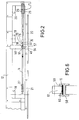
- Fig. 2
- den Gegenstand der Fig. 1 in einer teilweisen Draufsicht,
- Fig. 3
- den Gegenstand der Fig. 1 in einem senkrechten Querschnitt nach Linie III-III,
- Fig. 4
- den Gegenstand der Fig. 1 in einem senkrechten Querschnitt nach Linie IV-IV,
- Fig. 5
- eine Einzelheit der Fig. 1 in einem senkrechten Längsschnitt, die die Verbindungseinrichtung und die Klemmvorrichtung in vereinfachter, schematischer Darstellung in vergrößertem Maßstab zeigt und
- Fig. 6
- einen Teilschnitt nach Linie VI-VI der Fig. 1.
- In den Zeichnungen ist mit 10 eine Bandabroll- und -Zuführvorrichtung bezeichnet, mit der ein Umreifungsband - im folgenden kurz nur als "Band" 11 bezeichnet - aus thermosensitivem Kunststoff, beispielsweise aus Polypropylen, einer nicht dargestellten Umreifungsstation für Packstücke zugeführt wird.
- Die Bandabroll- und-Zuführvorrichtung besteht aus einem Grundrahmen 12, auf dem eine Klettersäule 13 mit einer Bandspeichervorrichtung 14, 15 und ein Lagerrahmen 16 angeordnet sind. Der Lagerrahmen 16 hat eine Tischplatte 17, die von drei Pfostenpaaren 18, 19 und 20 getragen wird, die durch hier nicht näher dargestellte Traversen und Streben seitlich ausgesteift sind. An den Pfosten 18 ist eine erste Vorratsrolle 21 und an den Pfosten 19 ist eine zweite Vorratsrolle 22 drehbar gelagert. Auf jeder Vorratsrolle 21 und 22 ist eine beträchtliche Länge Band 11a bzw. 11b aufgewickelt, das über mehrere Umlenkrollen 24a, 24b, 25, 26 und 27 der Bandspeichervorrichtung 14 und 15 und von dort der Umreifungsstation zugeführt wird, wie dies durch den Pfeil 28 angedeutet ist. Jede Vorratsrolle 21, 22 hat eine Bremse 29 bzw. 30, welche verhindert, daß sich die Vorratsrolle mit einer höheren Geschwindigkeit dreht als dies der Bandabzugsgeschwindigkeit entspricht.
- Die Bandspeichervorrichtung besteht aus einem am oberen Ende der Klettersäule 13 fest angeordneten Rollenblock 15 mit mehreren, auf einer gemeinsamen, festen Achse 31 frei drehbar gelagerten Rollen 32 und aus einem am unteren Ende der Klettersäule 13 vertikal verschiebbar gelagerten beweglichen Rollenblock 14, der auf einer an der Klettersäule 13 vertikal verschiebbaren Achse 33 frei drehbare Rollen 34 trägt. Das von der Bandabroll- und Zuführvorrichtung 10 abgezogene Band 11 ist achtfach über die Rollen 32 und 34 der Rollenblöcke 15 und 14 geführt und wird vom oberen Rollenblock 15 aus der bandverarbeitenden Einrichtung zugeführt. Hierbei kann der bewegliche Rollenblock 14 an der Klettersäule 13 nach oben wandern, wenn das Band 11 in der Bandabroll- und -Zuführvorrichtung 10 festgehalten wird und kein Band in die Bandspeichervorrichtung nachläuft.
- Die in den Zeichnungen dargestellte Bandabroll- und -Zuführvorrichtung 10 ist mit einer Verbindungsvorrichtung 35, einer Klemmvorrichtung 36, einer Kalibriervorrichtung 37 und einer Transportvorrichtung 38 versehen, die in geeigneter Weise auf oder unter der Tischplatte 17 angeordnet sind. In Bewegungsrichtung 39 im Abstand vor der Verbindungsvorrichtung 35 ist an der Säule 20 zwischen den Umlenkrollen 24a und 24b einerseits und 25 und 26 andererseits ein Sensor 40 mit Schaltvorrichtung angeordnet, der das jeweils an ihm vorbeilaufende Bandende der ersten Vorratsrolle 21 oder der zweiten Vorratsrolle 22 abtastet und die Verbindungsvorrichtung 35 einschaltet.
- Die Verbindungsvorrichtung 35 ist eine an sich bekannte Reibschweißvorrichtung, wie sie üblicherweise zum Verbinden der Enden einer Bandumreifung verwendet wird. Diese Reibschweißvorrichtung hat eine hin- und herbewegliche Reibbacke 42, die über einen Exzenter 43 von einem Motor 44 quer zur Bandlängsrichtung hin- und hergeschwenkt wird, während sie von einem Druckstempel 45 mit dem oben liegenden Bandende 11b auf einen unten liegenden Bandanfang 11a gedrückt wird. Durch die erzeugte Reibungswärme werden die thermoplastischen Kunststoffbänder an ihrer Oberfläche erwärmt und miteinander verschweißt, sobald die Reibbacke 42 zum Stillstand kommt.
- In Bewegungsrichtung 39 vor der Reibbacke 42 befindet sich ein Messer 46, das am hinteren Rand eines federbelasteten Haltestempels 47 angeordnet ist und das hintere Bandende 11b abschneidet und hierbei zugleich auf den darunterliegenden Bandanfang drückt und diesen mit festhält, wenn die Reibbacke 42 die Schweißverbindung herstellt.
- Die in Bewegungsrichtung 39 hinter der Verbindungsvorrichtung angeordnete Kalibriervorrichtung 37 besteht im wesentlichen aus einer von einem Motor 48 drehend angetriebenen Glättrolle 49, die an einem dreieckigen Kipphebel 50 gelagert ist und von einem pneumatischen Zylinder 51 auf eine Gegendruckfläche 52 in der Bewegungsbahn des Bandes 11 niedergeschwenkt werden kann. Die Glättrolle 49 trägt auf ihrem Umfang ein Schleifmittel 53 und auf ihren beiden Stirnseiten Kreismesser 54 und 55, die mit ihren über den Außenumfang der Glättrolle vorstehenden Rändern 56 und 57 Messerkanten bilden.
- In Bewegungsrichtung 39 hinter der Kalibriervorrichtung 37 und vor der letzten Umlenkrolle 27 ist die Transportvorrichtung 38 angeordnet. Diese besteht aus einem auf dem Tisch 17 in Bandlängsrichtung verschiebbaren Schlitten 58, der an seiner Oberseite einen nach oben offenen Bandkanal 59 aufweist, durch den das Band 11 hindurchläuft und auf dessen Boden 60 das Band mit einer Bandklemme 61 festgeklemmt werden kann. Die Bandklemme 61 ist eine sogenannte "Froschklemme" die entgegen der Bewegungsrichtung 39 des Bandes 11 selbstklemmend ist und am Ende der Kolbenstange 62 eines pneumatischen Antriebszylinders 63 angelenkt ist, der die Bandklemme 61 und mit ihr das im Bandkanal 59 festgeklemmte Band 11 mitsamt dem Schlitten 58 in Bewegungsrichtung 39 schieben kann.
- Unterhalb der Verbindungsvorrichtung 35 befindet sich ein An-Schlag 64 für den Bandanfang 11a der zweiten Vorratsrolle 22, der bis zum Anschweißen an das Bandende 11b von der Klemmvorrichtung 36 festgehalten wird. Die Klemmvorrichtung 36 ist unterhalb der Tischplatte 17 angeordnet und um eine horizontale Achse 65 aus der Bewegungsbahn des Bandes 11 nach vorne ausschwenkbar (Fig. 4). Die Klemmvorrichtung 36 hat einen an ihrer Rückseite 66 offenen Banddurchlaß 67, der oberseitig von einer Klemmplatte 68 begrenzt wird, die von einen pneumatischen Klemmenantriebszylinder 69 auf das in den Banddurchlaß 67 eingelegte Band niedergezogen wird und dieses festklemmt. Eine Sperrklinke 70 greift in eine hierfür vorgesehene Raste 71 am Antriebszylinder 69 ein und hält die Klemmvorrichtung 36 in ihrer senkrechten Bereitstellungslage, in der sich der Bandanfang 11a in der Bewegungsbahn des Bandes 11 befindet. Beim Niederfahren des Druckstempels 45 und des Haltestempels 47 wird diese Sperrklinke 70 von einem an der Verbindungsvorrichtung 35 angeordneten, nicht näher dargestellten Betätigungsglied aus der Raste 71 ausgehoben, wobei gleichzeitig der Antriebszylinder 69 die Klemmplatte 68 lüftet. Eine am Klemmenantriebszylinder 69 angreifende Feder 72 schwenkt dann die Klemmvorrichtung 36 nach vorn, wobei der nun von dem federbelasteten Haltestempel 47 der Verbindungsvorrichtung 35 festgehaltene Bandanfang 11a nach hinten aus dem Banddurchlaß 67 der Klemmvorrichtung 36 austritt.
- Die Wirkungsweise der Vorrichtung ist folgende:
Solange die zweite Vorratsrolle 22 eine genügende Bandmenge enthält, wird das Band 11 in Richtung des Pfeiles 28 von der Bandspeichervorrichtung 14, 15 abgezogen. Hierbei befindet sich der untere, bewegliche Rollenblock 14 in seiner in Fig. 1 dargestellten tiefsten Lage und das Band 11 läuft um alle Rollen 32 und 34 der Rollenblöcke 14 und 15 um, wobei es dem oberen Rollenblock zugeführt wird und ungehindert von der zweiten Vorratsrolle 22 abgezogen wird. Es läuft hierbei um die Umlenkrollen 24b, 26 und 27, während sich die Verbindungsvorrichtung 35, die Kalibriervorrichtung 37 und die Transportvorrichtung 38 in ihren unwirksamen Lagen befinden. - Während das Band 11 von der zweiten Vorratsrrolle 22 abgezogen wird, kann die Bedienungsperson eine volle, erste Vorratsrolle 21 auf ihre Achse im Lagerrahmen 16 aufstecken, den Bandanfang 11a um die Umlenkrollen 24a und 25 bis zum Anschlag 64 führen und von hinten her in den Banddurchlaß 67 der vorgeschwenkten Klemmvorrichtung 36 einlegen. Die Bedienungsperson schwenkt dann die Klemmvorrichtung 36 in ihre senkrechte, in Fig. 4 in ausgezogenen Linien dargestellte Lage, in der sie von der Sperrklinke 70 verriegelt wird, die hierbei gleichzeitig den Klemmenantriebszylinder 69 aktiviert, der mit seiner Klemmplatte 68 den Bandanfang 11a festklemmt.
- Wenn der auf der zweiten Vorratsrolle 22 befindliche Bandvorrat aufgebraucht ist und das Bandende 11b an dem Sensor 40 vorbeiläuft, schaltet dessen Schaltvorrichtung die Verbindungsvorrichtung 35 ein, deren Motor 44 die Reibbacke 42 hin- und herbewegt und deren pneumatischer Antriebszylinder 73 den Druckstempel 45 auf die Reibbacke 42 und den federbelasteten Haltestempel 47 auf das Bandende 11b drückt. Das Messer 46 schneidet hierbei das Bandende 11b ab, welches hierdurch frei wird und nach unten fallen kann.
- Durch die hin- und hergehende Bewegung der Reibbacke 42 wird der vor dem Messer 46 verbliebene Teil des Bandendes unter Druck auf dem Bandanfang 11a hin- und hergeschwenkt und hierdurch Reibungswärme erzeugt. Hierdurch werden die einander zugewandten Oberflächen der Bänder 11a und 11b erweicht und miteinander verschweißt, sobald die Reibbacke 42 bei gleichzeitigem Ausüben eines Anpreßdruckes die Bänder aufeinander drückt, wobei sich eine Verbindungsstelle 72 ergibt, die sich von dem Anschlag 64 bis zum Messer 46 erstreckt.
- Durch den Schweißvorgang und das nachfolgende Zusammenpressen des Endes des einen Bandes und des Anfanges des anderen Bandes kann ein wenig erweichtes Bandmaterial seitlich austreten und auf die Bandoberfläche 75 gelangen. Da dieser Schweißwulst auf der Bandoberfläche 75 und an den seitlichen Bandrändern 76 bei der nachfolgenden Verarbeitung des Bandes Schwierigkeiten bereiten kann, ist es notwendig, diese Schweißwülste zu entfernen und die Bandoberfläche 75 zu glätten und die Bandränder 76 im Bereich der Verbindungsstelle 74 zu beschneiden. Diese nachfolgende Bearbeitung wird von der Kalibriervorrichtung 37 durchgeführt.
- Sobald die Verbindungsstelle 74 hergestellt ist, lüftet der Klemmenantriebszylinder 69 die Klemmplatte 68. Die Feder 72 schwenkt dann die Klemmvorrichtung 36 nach vorn, wobei der Bandanfang 11a der ersten Vorratsrolle 21 aus dem Banddurchlaß 67 austritt. Das im Bandkanal 59 des Schlittens 58 liegende Band wird nun von der Bandklemme 61 festgeklemmt und langsam in Bewegungsrichtung 39 durch die Kalibriervorrichtung 37 gezogen, wobei sich der Schlitten 58 in Pfeilrichtung bewegt. Die von dem pneumatischen Zylinder 51 auf die Gegendruckfläche 52 niedergeschwenkte Glättrolle 49 schleift nun die Bandoberfläche 75 ab, wobei gleichzeitig die Messerkanten 54 und 55 der Kreismesser die Bandränder 76 glattschneiden.
- Sobald die Verbindungsstelle 74 vollständig durch die Kalibriervorrichtung 37 hindurchgelaufen ist, wird der Schlitten 58 von dem pneumatischen Antriebszylinder 63 in seine Ausgangslage zurückgefahren. Hierdurch schwenkt die Bandklemme 61 zurück und gibt das Band 11 frei, das nun ungehindert durch den Bandkanal 59 gezogen werden kann, nachdem die Glättrolle 49 vom pneumatischen Zylinder 51 hochgeschwenkt und auch die Reibbacke 42 und die Stempel 45 und 47 der Verbindungsvorrichtung aus der Bewegungsbahn des Bandes herausgefahren worden sind.
- Das Band 11 wird nun von der ersten Vorratsrolle abgezogen, füllt die Bandspeichervorrichtung 14, 15 wieder und die Bedienungsperson kann den leeren Kern der zweiten Vorratsrolle 22 abnehmen und eine volle Vorratsrolle aufstecken und nun deren Anfang in die Klemmvorrichtung 36 einlegen, wie dies weiter oben beschrieben worden ist.
- Die Erfindung ist nicht auf die dargestellte und beschriebene Ausführungsform beschränkt, sondern es sind mehrere Änderungen und Ergänzungen möglich, ohne den Rahmen der Erfindung zu verlassen. Beispielsweise ist es auch möglich, die Enden von Stahlbändern beispielsweise durch Punktschweißung mit einer geeigneten Vorrichtung zu verbinden, oder andere Bänder, beispielsweise Papierbänder durch einen geeigneten Klebstoff aneinander zu kleben, um kontinuierlich von einer Vorratsrolle auf eine andere überzugehen. Je nach Art der verwendeten Bänder kann auch die Kalibriereinrichtung etwas anders ausgebildet sein.
Claims (10)
- Vorrichtung zum kontinuierlichen Zuführen eines Bandes, insbesondere eines Kunststoffbandes von einem Vorrat zu einer bandverarbeitenden Einrichtung, insbesondere zu einer Bandumreifungseinrichtung, mit einer ersten Vorratsrolle und einer zweiten Vorratsrolle, von denen der Bandanfang der einen Vorratsrolle einer Bandvorschubeinrichtung zugeführt wird, sobald das Bandende der anderen Vorratsrolle erreicht ist, gekennzeichnet durch eine Verbindungsvorrichtung (35) zum Verbinden des Bandendes (11b) der einen Vorratsrolle (22) mit dem Bandanfang (11a) der anderen Vorratsrolle (21); durch eine Klemmvorrichtung (36) zum Einlegen, Halten und Bereitstellen eines Bandanfanges (11a) für die Verbindungsvorrichtung (35), durch eine Kalibriervorrichtung (37) zum Kalibrieren und Glätten der Bandverbindungsstelle (74) und durch eine Bandspeichervorrichtung (14,15) die der Verbindungsvorrichtung (35) und der Kalibriervorrichtung (37) nachgeschaltet ist und von der aus das Band (11) der bandverarbeitenden Einrichtung zugeführt wird.
- Vorrichtung nach Anspruch 1, dadurch gekennzeichnet, daß in Bewegungsrichtung (39) des Bandes (11) im Abstand von der Verbindungsvorrichtung (35) ein Sensor (40) mit einer Schaltvorrichtung angeordnet ist, der das Bandende (11b) einer Vorratsrolle (22) erfaßt und die Verbindungsvorrichtung (35) aktiviert.
- Vorrichtung nach Anspruch 1 oder 2, dadurch gekennzeichnet, daß zwischen der Kalibriervorrichtung (37) und der Bandspeichervorrichtung (14,15) eine Transportvorrichtung (38) mit einer Bandklemme (61) angeordnet ist, die das Band (11) festhält und die fertige Bandverbindungsstelle (74) durch die Kalibriervorrichtung (38) zieht.
- Vorrichtung nach einem der Ansprüche 1 bis 3, dadurch gekennzeichnet, daß die Verbindungsvorrichtung (35) eine Schweißvorrichtung ist, die das Bandende (11b) der einen Vorratsrolle (22) mit dem Bandanfang (11a) der anderen Vorratsrolle (21) durch Druck und Wärme verbindet.
- Vorrichtung nach einem der Ansprüche 1 bis 4, dadurch gekennzeichnet, daß die Verbindungsvorrichtung (35) eine Reibschweißvorrichtung (41) ist, die ein Messer (46) zum Abschneiden des Bandendes (11b) und eine Reibbacke 42) zum Hin- und Herbewegen des Bandendes (11b) der einen Vorratsrolle (22) unter Druck auf dem Bandanfang (11a) der anderen Vorratsrolle (21) zum Erzeugen von Reibungswärme zwischen den Berührungsflächen von Bändern aus thermosensitivem Material aufweist.
- Vorrichtung nach einem der Ansprüche 1 bis 5, dadurch gekennzeichnet, daß die Kalibriervorrichtung (37) mindestens eine Glättfläche zum Glätten der Bandoberfläche (75) im Bereich der Verbindungsstelle (72) und zwei Messer (54, 55) zum Glätten der Bandränder (76) im Bereich der Verbindungsstelle (74) aufweist.
- Vorrichtung nach einem der Ansprüche 1 bis 6, dadurch gekennzeichnet, daß die Kalibriervorrichtung eine drehend angetriebene Glättrolle (49) aufweist, die auf ihrem Umfang ein Schleifmittel (53) trägt und an ihren Rändern (56, 57) mit Messerkanten (54, 55) versehen ist.
- Vorrichtung nach einem der Ansprüche 1 bis 7, dadurch gekennzeichnet, daß die Glättrolle (49) in der Bewegungsbahn des Bandes (11) vor- und zurückbewegbar ist und mit einer Gegendruckfläche (52) zusammenwirkt, über die das Band (11) hinweggezogen wird.
- Vorrichtung nach einem der Ansprüche 1 bis 8, dadurch gekennzeichnet , daß die Transportvorrichtung (38) einen von einem Antrieb (63) in Bandlängsrichtung bewegbaren Schlitten (58) mit einem Bandkanal (59) aufweist, in dem das Band (11) mit der Bandklemme (61) festklemmbar ist.
- Vorrichtung nach einem der Ansprüche 1 bis 9, dadurch gekennzeichnet, daß die Klemmvorrichtung (36) aus der Bewegungsbahn des Bandes (11) ausschwenkbar und mit einem Klemmantrieb (69) versehen ist, der von der Verbindungsvorrichtung (35) aktivierbar ist und hierbei seine Schwenkvorrichtung freigibt.
Applications Claiming Priority (2)
| Application Number | Priority Date | Filing Date | Title |
|---|---|---|---|
| DE4400154 | 1994-01-05 | ||
| DE19944400154 DE4400154A1 (de) | 1994-01-05 | 1994-01-05 | Vorrichtung zum kontinuierlichen Zuführen eines Bandes zu einer bandverarbeitenden Einrichtung |
Publications (1)
| Publication Number | Publication Date |
|---|---|
| EP0662438A1 true EP0662438A1 (de) | 1995-07-12 |
Family
ID=6507476
Family Applications (1)
| Application Number | Title | Priority Date | Filing Date |
|---|---|---|---|
| EP19940120058 Withdrawn EP0662438A1 (de) | 1994-01-05 | 1994-12-17 | Vorrichtung zum kontinuierlichen Zuführen eines Bandes zu einer bandverarbeitenden Einrichtung |
Country Status (3)
| Country | Link |
|---|---|
| EP (1) | EP0662438A1 (de) |
| CZ (1) | CZ334494A3 (de) |
| DE (1) | DE4400154A1 (de) |
Cited By (1)
| Publication number | Priority date | Publication date | Assignee | Title |
|---|---|---|---|---|
| WO2005097643A1 (de) * | 2004-04-07 | 2005-10-20 | Illinois Tool Works Inc. | Auto-splice-system |
Families Citing this family (2)
| Publication number | Priority date | Publication date | Assignee | Title |
|---|---|---|---|---|
| FR3015962B1 (fr) * | 2013-12-26 | 2016-01-01 | Spoolex | Procede de raboutage de deux articles thermofusibles sous forme de bandes ou de nappes, et module de raboutage pour la mise en œuvre dudit procede |
| IT201700089185A1 (it) * | 2017-08-02 | 2019-02-02 | Messersi Packaging Srl | Macchina reggiatrice con gruppo perfezionato di alimentazione della reggia |
Citations (1)
| Publication number | Priority date | Publication date | Assignee | Title |
|---|---|---|---|---|
| DE2703356A1 (de) * | 1976-03-24 | 1977-09-29 | Gen Foods Corp | Vorrichtung zur ermittlung von passmarken in den freien teilen einer spur, die durch freie und belegte teile sich wiederholender muster auf einer bewegten bahn verlaeuft |
Family Cites Families (4)
| Publication number | Priority date | Publication date | Assignee | Title |
|---|---|---|---|---|
| DD89041B1 (de) * | 1971-05-20 | 1981-01-28 | Achim Kratzsch | Vorrichtung zum ankleben von faelzelstreifen |
| IT1245994B (it) * | 1991-02-26 | 1994-11-07 | Gd Spa | Metodo per l'alimentazione in continuo, ad una macchina utilizzatrice,di un nastro provvisto di tacche distribuite con passo costante. |
| IT1253282B (it) * | 1991-10-16 | 1995-07-14 | Gd Spa | Dispositivo per la giunzione automatica di nastrini di ridotte dimensioni trasversali |
| DE4138800A1 (de) * | 1991-11-26 | 1993-05-27 | Signode Bernpak Gmbh | Verfahren und vorrichtung zur vermeidung von umreifungsmittelbedingten betriebsunterbrechungen an maschinen zum umreifen von packstuecken |
-
1994
- 1994-01-05 DE DE19944400154 patent/DE4400154A1/de not_active Withdrawn
- 1994-12-17 EP EP19940120058 patent/EP0662438A1/de not_active Withdrawn
- 1994-12-30 CZ CZ943344A patent/CZ334494A3/cs unknown
Patent Citations (1)
| Publication number | Priority date | Publication date | Assignee | Title |
|---|---|---|---|---|
| DE2703356A1 (de) * | 1976-03-24 | 1977-09-29 | Gen Foods Corp | Vorrichtung zur ermittlung von passmarken in den freien teilen einer spur, die durch freie und belegte teile sich wiederholender muster auf einer bewegten bahn verlaeuft |
Cited By (1)
| Publication number | Priority date | Publication date | Assignee | Title |
|---|---|---|---|---|
| WO2005097643A1 (de) * | 2004-04-07 | 2005-10-20 | Illinois Tool Works Inc. | Auto-splice-system |
Also Published As
| Publication number | Publication date |
|---|---|
| DE4400154A1 (de) | 1995-07-06 |
| CZ334494A3 (en) | 1995-08-16 |
Similar Documents
| Publication | Publication Date | Title |
|---|---|---|
| DE1704146C3 (de) | Verfahren und Einrichtung zum kontinuierlichen Herstellen von Beuteln Ausscheidung aus 1248911 | |
| DE1906939C3 (de) | Vorrichtung zurri StoBverbinden zweier in Laufrichtung aufeinanderfolgender dünner Warenbahnen | |
| AT393983B (de) | Schneidanlage zum ausschneiden von zuschnitten aus bandfoermigem ausgangsmaterial, insbesondere von ein- oder beidseitig folienbedeckten prepregs | |
| EP2049327A1 (de) | Verfahren zum herstellen von verpackungsbeuteln mit verstärktem bodenbereich sowie vorrichtung zur durchführung des verfahrens | |
| DE2708066C3 (de) | Vorrichtung zum Anbringen von mit Klebstoff versehenen Einfaßstreifen zum Binden von Blattlagen | |
| DE10301347A1 (de) | Banderoliermaschine | |
| DE3422170C2 (de) | ||
| EP0453727B1 (de) | Vorrichtung zum Spleissen von Bahnen, insbesondere von Papierbahnen für die Herstellung von Wellpappe | |
| DE1509878A1 (de) | Verfahren und Vorrichtung zur Anbringung von Abdichtungsstreifen | |
| DE4113772A1 (de) | Verfahren zum ersetzen von streifenmaterial an einer fertigungsmaschine | |
| DE2044820C3 (de) | Vorrichtung zum Abschneiden eines Materialblattes von einer Materialbahn | |
| DE1586093B2 (de) | Vorrichtung zum aufbringen von aufreisstreifen auf ein einschlagmaterialband | |
| DE2708853A1 (de) | Vorrichtung zum durchtrennen und gleichzeitigem verblocken eines aus folienfoermigen abschnitten gebildeten stapels | |
| DE2817597C2 (de) | Vorrichtung zum Ankleben des Endes einer ablaufenden ersten Materialbahn an den Anfang einer zweiten Materialbahn | |
| DE2914696C2 (de) | Vorrichtung zum Aufbringen von mit einem Kleber versehenen Reiterbändern auf die flachliegenden Stirnkanten von Schlauchabschnitten oder Säcken | |
| EP0662438A1 (de) | Vorrichtung zum kontinuierlichen Zuführen eines Bandes zu einer bandverarbeitenden Einrichtung | |
| DE2129626A1 (de) | Vorrichtung zur Herstellung gefuellter Verpackungen | |
| DE1871629U (de) | Buchblock-hinterklebe- und kaptalmaschine. | |
| DE3239069C2 (de) | Verfahren und Vorrichtung zum Herstellen geformter Käselaibe | |
| DE2354974A1 (de) | Verfahren und vorrichtung zum stapeln und ablegen von beuteln | |
| EP0315882A1 (de) | Verfahren zum Verpacken von Verpackungsgut in Verpackungsbeuteln unter Verwendung einer Schlauchfolie sowie Vorrichtung zum Durchführen dieses Verfahrens | |
| DE2112353A1 (de) | Verfahren und Vorrichtung zum Bilden von Paketen aus flachen Werkstuecken,insbesondere aus Schlauchabschnitten | |
| DE10134508A1 (de) | Verfahren zum Zusammenfassen von Beuteln, Vorrichtung zur Durchführung des Verfahrens und Beutelkette, sowie Beutelstapelkette | |
| DE60008463T2 (de) | Verfahren und Vorrichtung zum Verbinden der Enden von Materialbahnen, insbesondere Textilbahnen | |
| DE4318579C2 (de) | Vorrichtung zum Ablängen und Lochen von streifenförmigem Band |
Legal Events
| Date | Code | Title | Description |
|---|---|---|---|
| PUAI | Public reference made under article 153(3) epc to a published international application that has entered the european phase |
Free format text: ORIGINAL CODE: 0009012 |
|
| AK | Designated contracting states |
Kind code of ref document: A1 Designated state(s): AT BE CH DE DK ES FR GB IT LI LU NL SE |
|
| RAX | Requested extension states of the european patent have changed |
Free format text: SI PAYMENT 941217 |
|
| 17P | Request for examination filed |
Effective date: 19951221 |
|
| GRAG | Despatch of communication of intention to grant |
Free format text: ORIGINAL CODE: EPIDOS AGRA |
|
| 17Q | First examination report despatched |
Effective date: 19980903 |
|
| STAA | Information on the status of an ep patent application or granted ep patent |
Free format text: STATUS: THE APPLICATION HAS BEEN WITHDRAWN |
|
| 18W | Application withdrawn |
Withdrawal date: 19990107 |