EP0660492B1 - Système de refroidissement d'un moteur - Google Patents
Système de refroidissement d'un moteur Download PDFInfo
- Publication number
- EP0660492B1 EP0660492B1 EP94890196A EP94890196A EP0660492B1 EP 0660492 B1 EP0660492 B1 EP 0660492B1 EP 94890196 A EP94890196 A EP 94890196A EP 94890196 A EP94890196 A EP 94890196A EP 0660492 B1 EP0660492 B1 EP 0660492B1
- Authority
- EP
- European Patent Office
- Prior art keywords
- rotor shaft
- shaft
- gearbox
- cooling system
- oil
- Prior art date
- Legal status (The legal status is an assumption and is not a legal conclusion. Google has not performed a legal analysis and makes no representation as to the accuracy of the status listed.)
- Expired - Lifetime
Links
Images


Classifications
-
- F—MECHANICAL ENGINEERING; LIGHTING; HEATING; WEAPONS; BLASTING
- F16—ENGINEERING ELEMENTS AND UNITS; GENERAL MEASURES FOR PRODUCING AND MAINTAINING EFFECTIVE FUNCTIONING OF MACHINES OR INSTALLATIONS; THERMAL INSULATION IN GENERAL
- F16H—GEARING
- F16H57/00—General details of gearing
- F16H57/04—Features relating to lubrication or cooling or heating
- F16H57/0412—Cooling or heating; Control of temperature
-
- H—ELECTRICITY
- H02—GENERATION; CONVERSION OR DISTRIBUTION OF ELECTRIC POWER
- H02K—DYNAMO-ELECTRIC MACHINES
- H02K7/00—Arrangements for handling mechanical energy structurally associated with dynamo-electric machines, e.g. structural association with mechanical driving motors or auxiliary dynamo-electric machines
- H02K7/10—Structural association with clutches, brakes, gears, pulleys or mechanical starters
- H02K7/116—Structural association with clutches, brakes, gears, pulleys or mechanical starters with gears
-
- H—ELECTRICITY
- H02—GENERATION; CONVERSION OR DISTRIBUTION OF ELECTRIC POWER
- H02K—DYNAMO-ELECTRIC MACHINES
- H02K9/00—Arrangements for cooling or ventilating
- H02K9/19—Arrangements for cooling or ventilating for machines with closed casing and closed-circuit cooling using a liquid cooling medium, e.g. oil
- H02K9/193—Arrangements for cooling or ventilating for machines with closed casing and closed-circuit cooling using a liquid cooling medium, e.g. oil with provision for replenishing the cooling medium; with means for preventing leakage of the cooling medium
-
- H—ELECTRICITY
- H02—GENERATION; CONVERSION OR DISTRIBUTION OF ELECTRIC POWER
- H02K—DYNAMO-ELECTRIC MACHINES
- H02K9/00—Arrangements for cooling or ventilating
- H02K9/19—Arrangements for cooling or ventilating for machines with closed casing and closed-circuit cooling using a liquid cooling medium, e.g. oil
- H02K9/197—Arrangements for cooling or ventilating for machines with closed casing and closed-circuit cooling using a liquid cooling medium, e.g. oil in which the rotor or stator space is fluid-tight, e.g. to provide for different cooling media for rotor and stator
Definitions
- the invention relates to a cooling system for an electric motor according to the preamble of patent claim 1.
- GB-A-2 032 703 shows cooling in the interior of a rotating housing, which, however, does not show the special structure of the subject invention, but is fixedly mounted on a fixed part in the interior of the rotating housing. In particular, it is not shaft cooling. Furthermore, water or another liquid is mentioned as the cooling medium and not the use of the gear oil as cooling medium according to the invention.
- GB-A-P16986 describes the rotor cooling of an electrical machine using water as the cooling medium, which is introduced through a fixed nozzle into a hollow rotor shaft and is returned through a ring of axially parallel bores on the outside of the rotor shaft.
- the nozzle is inserted with a sliding seal in a shaft section and the return bores open behind the seal of the nozzle into the annular cavity in said shaft section around the nozzle.
- GB-A-851 971 describes cooling of a motor with oil, the cooling medium flowing through the stator via spiral grooves on the inner surface and the oil being pumped into the hollow rotor shaft via a fixed pipe in order to cool the rotor.
- this reserve no co-rotating inner tube is used in the rotor shaft, into which the cooling medium is introduced via a fixed nozzle.
- the object of the invention is to provide a cooling system by means of which a shaft cooling is created which enables a high evaluation of the machine and can also be used for encapsulated motors which have the advantage that they are quiet.
- the existing transmission oil can thus be used in a simple manner for cooling the motor shaft and there is no need for it additional cooling device, line, pumps or the like. Can be provided for external cooling media. This makes the engine more powerful and yet light.
- a small wheel of the gearbox housed in the gearbox is inserted into the rotor shaft at the drive end thereof and has a channel in the continuation of a tube inside the hollow rotor shaft.
- the tube in the cavity of the rotor shaft is supported by spacers.
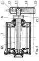
- FIG. 1 shows a cross section of the traction motor
- FIG. 2 shows a section along the line II-II of FIG. 1
- FIG. 3 shows a section along the line III-III of FIG. 1
- FIG. 4 shows a further embodiment of the cooling system .
- the motor consists of a fixed part, the stator or stator 1 and a rotating part, the rotor 2 or rotor.
- a stator winding 4 is embedded in the slots of a stator iron core 3.
- the rotor 2 has a rotor shaft 6 mounted in bearing plates 5, on which an iron sheet package 7 is clamped together by pressing rings 8, one of which is held on the shaft 6 on either side of the package.
- conductive rotor bars 9 are inserted, the ends of which are conductively connected to one another on both sides of the rotor by short-circuit rings 9 '.
- the stator 1 is enclosed by a cooling jacket 10, which has a spiral or meandering flow channel and through which a water-glycol mixture flows.
- the arrows A, B indicate the entry and exit of the mixture.
- other cooling systems can be used in the stator within the scope of the invention. For example, rib cooling is possible.
- a pinion or small wheel 13 which is inserted into the rotor shaft 6 and which drives a large wheel 14 which drives the drive axle of the locomotive.
- the small wheel 13 and the large wheel 14 are enclosed by a gear box 15 which, in contrast to the illustration, can also be double-walled.
- the rotor shaft 6 is hollow and forms an axial cavity 11, in which a tube 12 is inserted axially and, as shown in FIG. 2, is supported therein by preferably three spacers 20 arranged at equal angular intervals.
- the tube 12 connects at the drive end of the rotor shaft 6 to an axial cavity 16 of the small wheel 13, which opens into the oil space 18 of the gear box 15 via a nozzle 17.
- the tube 12 is enclosed by the cavity 11 of the rotor shaft 6, which communicates with the tube 12 at its end remote from the small wheel 13 and opens into the oil space 18 of the gearbox 15 via channels 19 at the other end.
- eight channels 19 arranged at equal angular intervals are provided on the drive-side end of the rotor shaft 6 and, as shown in FIG. 1, extend along the part of the small wheel 13 inserted into the rotor shaft 6 .
- the gear oil is injected axially from the gear box 15 by means of a pump 21 via the nozzle 17 into the tube 12 and at the end thereof, as with the arrow C is indicated, deflected into the cavity 11, from which it flows back via the channels 19 into the oil space 18 of the gearbox 15.
- FIG. 4 an embodiment according to FIG. 4 is possible, in which an extension of the rotor shaft 6 in the gear box 15 leads through a coupling 22, the extension being pierced and the gear oil being able to pass through the bore into the tube 12.
Claims (4)
- Système de refroidissement pour un moteur électrique comprenant une boîte d'engrenages (15), un arbre creux (6), refroidi à l'intérieur par liquide, un tube interne (12) coaxial, qui l'entraîne en rotation et un stator (1), refroidi à l'extérieur, en particulier pour un moteur à traction, caractérisé en ce q'un système de canaux (16, 17, 19), reliant l'arbre de rotor (6) et la bôite d'engrenages est prévu pour l'introduction axiale de l'huile à engrenages provenant de la chambre d'huile (18) de la boîte d'engrenages (15) en tant que réfrigérant vers l'intérieur du tube interne (12) de l'arbre de rotor (6), à une extrémité de cet arbre (6) et pour le prélevement axial et le renvoi de l'huile à engrenages sortant par la fente annulaire entre le tube interne (12) et la paroi interne de l'arbre de rotor depuis la même extrémité de l'arbre de rotor (6) afin de revenir dans la bôite d'engrenages (15).
- Système de refroidissement selon la revendication 1, caractérisé en ce qu'une petite roue (13) de l'engrenage (13, 14), logé dans la boîte d'engrenages (15), est insérée dans l'arbre de rotor (6), à son extrémité, côté entraînement, et présente un canal (16) dans le prolongement d'un tube (12) connu en soi à l'intérieur de l'arbre creux de rotor (6).
- Système de refroidissement selon la revendication 2, caractérisé en ce qu'il est prévu, autour de la partie de la petite roue (13), insérée dans l'arbre de rotor (6), un nombre de canaux (19), disposés dans la partie côté entraînement de l'arbre de rotor (6), canaux (19) qui débouchent, d'une part, dans l'espace creux (11) de l'arbre de rotor (6) et, d'autre part, dans la chambre à huile (18) de la boîte d'engrenages (15).
- Système de refroidissement selon la revendication 2, caractérisé en ce que le tube (12) prend appui dans l'expace creux (11) de l'arbre de rotor (6) par l'intermédiaire d'écarteurs (20).
Applications Claiming Priority (2)
| Application Number | Priority Date | Filing Date | Title |
|---|---|---|---|
| AT2610/93 | 1993-12-23 | ||
| AT261093 | 1993-12-23 |
Publications (2)
| Publication Number | Publication Date |
|---|---|
| EP0660492A1 EP0660492A1 (fr) | 1995-06-28 |
| EP0660492B1 true EP0660492B1 (fr) | 1997-09-03 |
Family
ID=3537347
Family Applications (1)
| Application Number | Title | Priority Date | Filing Date |
|---|---|---|---|
| EP94890196A Expired - Lifetime EP0660492B1 (fr) | 1993-12-23 | 1994-11-28 | Système de refroidissement d'un moteur |
Country Status (3)
| Country | Link |
|---|---|
| EP (1) | EP0660492B1 (fr) |
| AT (1) | ATE157822T1 (fr) |
| DE (1) | DE59403962D1 (fr) |
Cited By (3)
| Publication number | Priority date | Publication date | Assignee | Title |
|---|---|---|---|---|
| DE102017112348A1 (de) | 2017-06-06 | 2018-12-06 | Dr. Ing. H.C. F. Porsche Aktiengesellschaft | Elektrische Maschine |
| CN110193734A (zh) * | 2019-06-12 | 2019-09-03 | 安阳工学院 | 一种内推式液压拆卸准停永磁同步大功率松拉刀电主轴 |
| CN112092607A (zh) * | 2020-09-18 | 2020-12-18 | 中国第一汽车股份有限公司 | 一种电驱动系统的混合冷却系统及车辆 |
Families Citing this family (19)
| Publication number | Priority date | Publication date | Assignee | Title |
|---|---|---|---|---|
| AT403864B (de) * | 1994-06-13 | 1998-06-25 | Abb Daimler Benz Transp | Kühlsystem für eine elektrische maschine |
| ATA206795A (de) * | 1995-12-20 | 2002-06-15 | Bombardier Transp Gmbh | Einrichtung zur förderung des getriebeöls zur kühlung elektrischer maschinen |
| EP0811521B1 (fr) * | 1995-12-21 | 2002-08-21 | Aisin Aw Co., Ltd. | Dispositif d'entrainement pour automobiles electriques |
| DE19639098A1 (de) * | 1996-09-24 | 1998-03-26 | Wilo Gmbh | Motorpumpe mit gekühltem Frequenzumformer |
| EP0989658A1 (fr) | 1998-09-28 | 2000-03-29 | The Swatch Group Management Services AG | Machine électrique asynchrone refroidie par liquide |
| AT503361B1 (de) * | 1998-10-02 | 2011-10-15 | Daimler Ag | Antrieb |
| DE69923553T2 (de) * | 1999-08-10 | 2006-02-16 | The Swatch Group Management Services Ag | Antriebsvorrichtung mit einem flüssigkeitsgekühlten elektrischen Motor und Planetengetriebe |
| JP3794392B2 (ja) * | 2003-02-25 | 2006-07-05 | 日産自動車株式会社 | 電気自動車の駆動ユニット |
| DE10318022A1 (de) * | 2003-04-19 | 2004-11-04 | Linde Ag | Elektrische Maschine mit verbesserter Kühlung und Antriebsachse mit einer derartigen elektrischen Maschine |
| DE102011015623A1 (de) * | 2011-03-31 | 2012-10-04 | Magna Powertrain Ag & Co. Kg | Elektrische Antriebseinheit |
| DE102011055192B4 (de) * | 2011-11-10 | 2014-05-22 | Gkn Walterscheid Gmbh | Generatoreinheit |
| DE102013104711A1 (de) | 2013-05-07 | 2014-11-13 | Dr. Ing. H.C. F. Porsche Aktiengesellschaft | Elektrische Maschine mit gekühlter Rotorwelle |
| DE102014223642A1 (de) * | 2014-11-19 | 2016-05-19 | Zf Friedrichshafen Ag | Antriebseinrichtung |
| DE102015201450A1 (de) * | 2015-01-28 | 2016-07-28 | Deckel Maho Pfronten Gmbh | Mechanisches Getriebe einer Werkzeugmaschine |
| DE102016218819B4 (de) | 2016-09-29 | 2018-10-11 | Audi Ag | Kühlsystem |
| DE102017201117A1 (de) | 2017-01-24 | 2018-07-26 | Bayerische Motoren Werke Aktiengesellschaft | Verfahren zum Kühlen einer elektrischen Maschine sowie elektrische Maschine |
| EP3530989B1 (fr) | 2018-02-23 | 2020-08-05 | Valeo Siemens eAutomotive Germany GmbH | Agencement comprenant une machine électrique et une boîte de vitesses et véhicule |
| CN110277842A (zh) * | 2018-03-15 | 2019-09-24 | 蔚来汽车有限公司 | 带有冷却套件的电机 |
| CN115603491A (zh) * | 2021-07-08 | 2023-01-13 | 青岛海尔智能技术研发有限公司(Cn) | 一种立式转子冷却结构、电机及压缩机 |
Family Cites Families (6)
| Publication number | Priority date | Publication date | Assignee | Title |
|---|---|---|---|---|
| GB191416986A (en) * | 1914-07-17 | 1915-07-15 | Charles Algernon Parsons | Improvements in and relating to the Cooling of Dynamo Electric Machinery. |
| GB851971A (en) * | 1956-01-06 | 1960-10-19 | Napier & Son Ltd | Cooling arrangements for dynamo electric machines |
| GB1019804A (en) * | 1962-03-09 | 1966-02-09 | Mez Brno | High-speed dynamo-electric machine rotor |
| GB2032703B (en) * | 1978-10-18 | 1983-01-06 | Dowty Meco Ltd | Rotary drum device |
| US4418777A (en) * | 1981-09-11 | 1983-12-06 | Ford Motor Company | Transmission lubrication and motor cooling system |
| JPH0810976B2 (ja) * | 1989-01-25 | 1996-01-31 | ファナック株式会社 | モータの液冷構造 |
-
1994
- 1994-11-28 AT AT94890196T patent/ATE157822T1/de not_active IP Right Cessation
- 1994-11-28 EP EP94890196A patent/EP0660492B1/fr not_active Expired - Lifetime
- 1994-11-28 DE DE59403962T patent/DE59403962D1/de not_active Expired - Lifetime
Cited By (4)
| Publication number | Priority date | Publication date | Assignee | Title |
|---|---|---|---|---|
| DE102017112348A1 (de) | 2017-06-06 | 2018-12-06 | Dr. Ing. H.C. F. Porsche Aktiengesellschaft | Elektrische Maschine |
| CN110193734A (zh) * | 2019-06-12 | 2019-09-03 | 安阳工学院 | 一种内推式液压拆卸准停永磁同步大功率松拉刀电主轴 |
| CN110193734B (zh) * | 2019-06-12 | 2021-08-24 | 安阳工学院 | 一种内推式液压拆卸准停永磁同步大功率松拉刀电主轴 |
| CN112092607A (zh) * | 2020-09-18 | 2020-12-18 | 中国第一汽车股份有限公司 | 一种电驱动系统的混合冷却系统及车辆 |
Also Published As
| Publication number | Publication date |
|---|---|
| ATE157822T1 (de) | 1997-09-15 |
| DE59403962D1 (de) | 1997-10-09 |
| EP0660492A1 (fr) | 1995-06-28 |
Similar Documents
| Publication | Publication Date | Title |
|---|---|---|
| EP0660492B1 (fr) | Système de refroidissement d'un moteur | |
| DE102009051651B4 (de) | Windkraftgenerator mit Innenkühlkreislauf | |
| EP0317946B1 (fr) | Palier magnétique axial | |
| EP0493704B1 (fr) | Moteur électrique | |
| EP1248349A2 (fr) | Moteur électrique asynchrone | |
| DE102016209173A1 (de) | Rotor für eine elektrische Maschine | |
| EP0520333A1 (fr) | Unité de pompage | |
| DE2005802A1 (de) | Induktionsmotor | |
| DE102012202460A1 (de) | Elektromotorische Getriebevorrichtung mit einstückigem Gehäuse | |
| AT403864B (de) | Kühlsystem für eine elektrische maschine | |
| EP1181453A1 (fr) | Ensemble motopompe | |
| DE102016200423A1 (de) | Elektrische Maschine | |
| DE102014018223A1 (de) | Elektrische Maschine, insbesondere Asynchronmaschine | |
| DE102013020332A1 (de) | Elektrische Maschine, insbesondere Asynchronmaschine | |
| WO2002023699A2 (fr) | Moteur electrique refroidi par liquide | |
| DE102019200098A1 (de) | Fluidgekühlter Rotor für eine elektrische Maschine | |
| DE19919040A1 (de) | Elektromaschine, insbesondere Drehstrommaschine | |
| DE2307800A1 (de) | Kollektorloser gleichstrommotor fuer hohe drehzahlen | |
| DE2257301A1 (de) | Elektromotor, insbesondere fuer den antrieb zahnaerztlicher hand- und winkelstuecke | |
| EP3451507A1 (fr) | Machine tourante électrique pour une nacelle de propulsion | |
| DE102019120787A1 (de) | Elektrische Antriebseinheit, Hybridmodul und Antriebsanordnung für ein Kraftfahrzeug | |
| DE19623553A1 (de) | Flüssigkeitsgefüllter Unterwassermotor | |
| DE102020201127A1 (de) | Elektrischer Antrieb eines elektrisch angetriebenen Fahrzeugs | |
| DE69932309T2 (de) | Zwangskonvektions-Kühlangordnung für rotierende elektrische Maschinen | |
| DE102005052783A1 (de) | Verfahren zur Herstellung eines Stators für eine elektrische Maschine sowie entsprechender Stator und elektrische Maschine |
Legal Events
| Date | Code | Title | Description |
|---|---|---|---|
| PUAI | Public reference made under article 153(3) epc to a published international application that has entered the european phase |
Free format text: ORIGINAL CODE: 0009012 |
|
| AK | Designated contracting states |
Kind code of ref document: A1 Designated state(s): AT BE CH DE FR GB LI NL |
|
| 17P | Request for examination filed |
Effective date: 19951219 |
|
| RAP1 | Party data changed (applicant data changed or rights of an application transferred) |
Owner name: ABB DAIMLER-BENZ TRANSPORTATION AUSTRIA GMBH |
|
| GRAG | Despatch of communication of intention to grant |
Free format text: ORIGINAL CODE: EPIDOS AGRA |
|
| 17Q | First examination report despatched |
Effective date: 19961125 |
|
| GRAH | Despatch of communication of intention to grant a patent |
Free format text: ORIGINAL CODE: EPIDOS IGRA |
|
| GRAH | Despatch of communication of intention to grant a patent |
Free format text: ORIGINAL CODE: EPIDOS IGRA |
|
| GRAA | (expected) grant |
Free format text: ORIGINAL CODE: 0009210 |
|
| AK | Designated contracting states |
Kind code of ref document: B1 Designated state(s): AT BE CH DE FR GB LI NL |
|
| REF | Corresponds to: |
Ref document number: 157822 Country of ref document: AT Date of ref document: 19970915 Kind code of ref document: T |
|
| REG | Reference to a national code |
Ref country code: CH Ref legal event code: NV Representative=s name: KELLER & PARTNER PATENTANWAELTE AG Ref country code: CH Ref legal event code: EP |
|
| GBT | Gb: translation of ep patent filed (gb section 77(6)(a)/1977) |
Effective date: 19970904 |
|
| REF | Corresponds to: |
Ref document number: 59403962 Country of ref document: DE Date of ref document: 19971009 |
|
| ET | Fr: translation filed | ||
| PLBE | No opposition filed within time limit |
Free format text: ORIGINAL CODE: 0009261 |
|
| STAA | Information on the status of an ep patent application or granted ep patent |
Free format text: STATUS: NO OPPOSITION FILED WITHIN TIME LIMIT |
|
| 26N | No opposition filed | ||
| REG | Reference to a national code |
Ref country code: GB Ref legal event code: IF02 |
|
| REG | Reference to a national code |
Ref country code: CH Ref legal event code: PUE Owner name: BOMBARDIER TRANSPORTATION AUSTRIA GMBH TRANSFER- D Ref country code: CH Ref legal event code: PFA Free format text: ABB DAIMLER BENZ TRANSPORTATION AUSTRIA GMBH TRANSFER- BOMBARDIER TRANSPORTATION AUSTRIA GMBH |
|
| NLS | Nl: assignments of ep-patents |
Owner name: DAIMLERCHRYSLER AG |
|
| NLT1 | Nl: modifications of names registered in virtue of documents presented to the patent office pursuant to art. 16 a, paragraph 1 |
Owner name: BOMBARDIER TRANSPORTATION AUSTRIA GMBH |
|
| BECH | Be: change of holder |
Free format text: 20020215 *DAIMLERCHRISLER A.G. |
|
| PGFP | Annual fee paid to national office [announced via postgrant information from national office to epo] |
Ref country code: FR Payment date: 20051110 Year of fee payment: 12 |
|
| PGFP | Annual fee paid to national office [announced via postgrant information from national office to epo] |
Ref country code: NL Payment date: 20051114 Year of fee payment: 12 Ref country code: CH Payment date: 20051114 Year of fee payment: 12 |
|
| PGFP | Annual fee paid to national office [announced via postgrant information from national office to epo] |
Ref country code: AT Payment date: 20051115 Year of fee payment: 12 |
|
| PGFP | Annual fee paid to national office [announced via postgrant information from national office to epo] |
Ref country code: GB Payment date: 20051121 Year of fee payment: 12 |
|
| PGFP | Annual fee paid to national office [announced via postgrant information from national office to epo] |
Ref country code: BE Payment date: 20051216 Year of fee payment: 12 |
|
| PG25 | Lapsed in a contracting state [announced via postgrant information from national office to epo] |
Ref country code: AT Free format text: LAPSE BECAUSE OF NON-PAYMENT OF DUE FEES Effective date: 20061128 |
|
| PG25 | Lapsed in a contracting state [announced via postgrant information from national office to epo] |
Ref country code: LI Free format text: LAPSE BECAUSE OF NON-PAYMENT OF DUE FEES Effective date: 20061130 Ref country code: CH Free format text: LAPSE BECAUSE OF NON-PAYMENT OF DUE FEES Effective date: 20061130 Ref country code: BE Free format text: LAPSE BECAUSE OF NON-PAYMENT OF DUE FEES Effective date: 20061130 |
|
| PG25 | Lapsed in a contracting state [announced via postgrant information from national office to epo] |
Ref country code: NL Free format text: LAPSE BECAUSE OF NON-PAYMENT OF DUE FEES Effective date: 20070601 |
|
| REG | Reference to a national code |
Ref country code: CH Ref legal event code: PL |
|
| GBPC | Gb: european patent ceased through non-payment of renewal fee |
Effective date: 20061128 |
|
| NLV4 | Nl: lapsed or anulled due to non-payment of the annual fee |
Effective date: 20070601 |
|
| REG | Reference to a national code |
Ref country code: FR Ref legal event code: ST Effective date: 20070731 |
|
| PG25 | Lapsed in a contracting state [announced via postgrant information from national office to epo] |
Ref country code: GB Free format text: LAPSE BECAUSE OF NON-PAYMENT OF DUE FEES Effective date: 20061128 |
|
| BERE | Be: lapsed |
Owner name: *DAIMLERCHRISLER A.G. Effective date: 20061130 |
|
| PG25 | Lapsed in a contracting state [announced via postgrant information from national office to epo] |
Ref country code: FR Free format text: LAPSE BECAUSE OF NON-PAYMENT OF DUE FEES Effective date: 20061130 |
|
| PGFP | Annual fee paid to national office [announced via postgrant information from national office to epo] |
Ref country code: DE Payment date: 20130131 Year of fee payment: 19 |
|
| PG25 | Lapsed in a contracting state [announced via postgrant information from national office to epo] |
Ref country code: DE Free format text: LAPSE BECAUSE OF NON-PAYMENT OF DUE FEES Effective date: 20140603 |
|
| REG | Reference to a national code |
Ref country code: DE Ref legal event code: R119 Ref document number: 59403962 Country of ref document: DE Effective date: 20140603 |