EP0660492B1 - Cooling system for a motor - Google Patents
Cooling system for a motor Download PDFInfo
- Publication number
- EP0660492B1 EP0660492B1 EP94890196A EP94890196A EP0660492B1 EP 0660492 B1 EP0660492 B1 EP 0660492B1 EP 94890196 A EP94890196 A EP 94890196A EP 94890196 A EP94890196 A EP 94890196A EP 0660492 B1 EP0660492 B1 EP 0660492B1
- Authority
- EP
- European Patent Office
- Prior art keywords
- rotor shaft
- shaft
- gearbox
- cooling system
- oil
- Prior art date
- Legal status (The legal status is an assumption and is not a legal conclusion. Google has not performed a legal analysis and makes no representation as to the accuracy of the status listed.)
- Expired - Lifetime
Links
Images


Classifications
-
- F—MECHANICAL ENGINEERING; LIGHTING; HEATING; WEAPONS; BLASTING
- F16—ENGINEERING ELEMENTS AND UNITS; GENERAL MEASURES FOR PRODUCING AND MAINTAINING EFFECTIVE FUNCTIONING OF MACHINES OR INSTALLATIONS; THERMAL INSULATION IN GENERAL
- F16H—GEARING
- F16H57/00—General details of gearing
- F16H57/04—Features relating to lubrication or cooling or heating
- F16H57/0412—Cooling or heating; Control of temperature
-
- H—ELECTRICITY
- H02—GENERATION; CONVERSION OR DISTRIBUTION OF ELECTRIC POWER
- H02K—DYNAMO-ELECTRIC MACHINES
- H02K7/00—Arrangements for handling mechanical energy structurally associated with dynamo-electric machines, e.g. structural association with mechanical driving motors or auxiliary dynamo-electric machines
- H02K7/10—Structural association with clutches, brakes, gears, pulleys or mechanical starters
- H02K7/116—Structural association with clutches, brakes, gears, pulleys or mechanical starters with gears
-
- H—ELECTRICITY
- H02—GENERATION; CONVERSION OR DISTRIBUTION OF ELECTRIC POWER
- H02K—DYNAMO-ELECTRIC MACHINES
- H02K9/00—Arrangements for cooling or ventilating
- H02K9/19—Arrangements for cooling or ventilating for machines with closed casing and closed-circuit cooling using a liquid cooling medium, e.g. oil
- H02K9/193—Arrangements for cooling or ventilating for machines with closed casing and closed-circuit cooling using a liquid cooling medium, e.g. oil with provision for replenishing the cooling medium; with means for preventing leakage of the cooling medium
-
- H—ELECTRICITY
- H02—GENERATION; CONVERSION OR DISTRIBUTION OF ELECTRIC POWER
- H02K—DYNAMO-ELECTRIC MACHINES
- H02K9/00—Arrangements for cooling or ventilating
- H02K9/19—Arrangements for cooling or ventilating for machines with closed casing and closed-circuit cooling using a liquid cooling medium, e.g. oil
- H02K9/197—Arrangements for cooling or ventilating for machines with closed casing and closed-circuit cooling using a liquid cooling medium, e.g. oil in which the rotor or stator space is fluid-tight, e.g. to provide for different cooling media for rotor and stator
Definitions
- the invention relates to a cooling system for an electric motor according to the preamble of patent claim 1.
- GB-A-2 032 703 shows cooling in the interior of a rotating housing, which, however, does not show the special structure of the subject invention, but is fixedly mounted on a fixed part in the interior of the rotating housing. In particular, it is not shaft cooling. Furthermore, water or another liquid is mentioned as the cooling medium and not the use of the gear oil as cooling medium according to the invention.
- GB-A-P16986 describes the rotor cooling of an electrical machine using water as the cooling medium, which is introduced through a fixed nozzle into a hollow rotor shaft and is returned through a ring of axially parallel bores on the outside of the rotor shaft.
- the nozzle is inserted with a sliding seal in a shaft section and the return bores open behind the seal of the nozzle into the annular cavity in said shaft section around the nozzle.
- GB-A-851 971 describes cooling of a motor with oil, the cooling medium flowing through the stator via spiral grooves on the inner surface and the oil being pumped into the hollow rotor shaft via a fixed pipe in order to cool the rotor.
- this reserve no co-rotating inner tube is used in the rotor shaft, into which the cooling medium is introduced via a fixed nozzle.
- the object of the invention is to provide a cooling system by means of which a shaft cooling is created which enables a high evaluation of the machine and can also be used for encapsulated motors which have the advantage that they are quiet.
- the existing transmission oil can thus be used in a simple manner for cooling the motor shaft and there is no need for it additional cooling device, line, pumps or the like. Can be provided for external cooling media. This makes the engine more powerful and yet light.
- a small wheel of the gearbox housed in the gearbox is inserted into the rotor shaft at the drive end thereof and has a channel in the continuation of a tube inside the hollow rotor shaft.
- the tube in the cavity of the rotor shaft is supported by spacers.
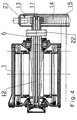
- FIG. 1 shows a cross section of the traction motor
- FIG. 2 shows a section along the line II-II of FIG. 1
- FIG. 3 shows a section along the line III-III of FIG. 1
- FIG. 4 shows a further embodiment of the cooling system .
- the motor consists of a fixed part, the stator or stator 1 and a rotating part, the rotor 2 or rotor.
- a stator winding 4 is embedded in the slots of a stator iron core 3.
- the rotor 2 has a rotor shaft 6 mounted in bearing plates 5, on which an iron sheet package 7 is clamped together by pressing rings 8, one of which is held on the shaft 6 on either side of the package.
- conductive rotor bars 9 are inserted, the ends of which are conductively connected to one another on both sides of the rotor by short-circuit rings 9 '.
- the stator 1 is enclosed by a cooling jacket 10, which has a spiral or meandering flow channel and through which a water-glycol mixture flows.
- the arrows A, B indicate the entry and exit of the mixture.
- other cooling systems can be used in the stator within the scope of the invention. For example, rib cooling is possible.
- a pinion or small wheel 13 which is inserted into the rotor shaft 6 and which drives a large wheel 14 which drives the drive axle of the locomotive.
- the small wheel 13 and the large wheel 14 are enclosed by a gear box 15 which, in contrast to the illustration, can also be double-walled.
- the rotor shaft 6 is hollow and forms an axial cavity 11, in which a tube 12 is inserted axially and, as shown in FIG. 2, is supported therein by preferably three spacers 20 arranged at equal angular intervals.
- the tube 12 connects at the drive end of the rotor shaft 6 to an axial cavity 16 of the small wheel 13, which opens into the oil space 18 of the gear box 15 via a nozzle 17.
- the tube 12 is enclosed by the cavity 11 of the rotor shaft 6, which communicates with the tube 12 at its end remote from the small wheel 13 and opens into the oil space 18 of the gearbox 15 via channels 19 at the other end.
- eight channels 19 arranged at equal angular intervals are provided on the drive-side end of the rotor shaft 6 and, as shown in FIG. 1, extend along the part of the small wheel 13 inserted into the rotor shaft 6 .
- the gear oil is injected axially from the gear box 15 by means of a pump 21 via the nozzle 17 into the tube 12 and at the end thereof, as with the arrow C is indicated, deflected into the cavity 11, from which it flows back via the channels 19 into the oil space 18 of the gearbox 15.
- FIG. 4 an embodiment according to FIG. 4 is possible, in which an extension of the rotor shaft 6 in the gear box 15 leads through a coupling 22, the extension being pierced and the gear oil being able to pass through the bore into the tube 12.
Abstract
Description
Die Erfindung betrifft ein Kühlsystem für einen Elektromotor nach dem Oberbegriff des Patentanspruchs 1.The invention relates to a cooling system for an electric motor according to the preamble of
Bei bekannten Motoren ist meist nur der Stator von einem Kühlmantel mit mäanderförmig verlaufendem Kanal umschlossen, welcher von einem Kühlmittel (Wasser-Glykol, Öl oder ähnlichem) durchströmt wird. Der Nachteil dieser Kühlung besteht bei einem Motor, insbesondere Kurzschlußläufer darin, daß die Wärme der Motorwelle und ihrer Lagerung nur über Umwege über das Blechpaket an den Statorkühlmantel abgeleitet werden kann. Dies hat zur Folge, daß die Lagertemperatur, vor allem im Innenring, sehr stark ansteigt, weil die Verluste in den leitfähigen Rotorteilen (Kupferwicklung) und die Eisenverluste, nicht genügend rasch abgeführt werden können.In known motors, usually only the stator is surrounded by a cooling jacket with a meandering channel through which a coolant (water-glycol, oil or the like) flows. The disadvantage of this cooling in a motor, especially short-circuit rotor, is that the heat of the motor shaft and its bearing can only be dissipated to the stator cooling jacket via the laminated core. As a result, the bearing temperature, especially in the inner ring, rises very sharply because the losses in the conductive rotor parts (copper winding) and the iron losses cannot be dissipated quickly enough.
Die GB-A-2 032 703 zeigt ein Kühlung im Inneren eines rotierenden Gehäuses, welche aber nicht den speziellen Aufbau der gegenständlichen Erfindung zeigt, sondern feststehend an einem feststehenden Teil im Inneren des rotierenden Gehäuses montiert ist. Insbesondere handelt es sich dabei um keine Wellenkühlung. Weiters ist als Kühlmedium Wasser oder eine andere Flüssigkeit erwähnt und nicht die erfindungsgemäße Verwendung des Getriebeöls als Kühlmedium.GB-A-2 032 703 shows cooling in the interior of a rotating housing, which, however, does not show the special structure of the subject invention, but is fixedly mounted on a fixed part in the interior of the rotating housing. In particular, it is not shaft cooling. Furthermore, water or another liquid is mentioned as the cooling medium and not the use of the gear oil as cooling medium according to the invention.
Die GB-A-P16986 beschreibt die Rotorkühlung einer elektrischen Maschine mit Wasser als Kühlmedium, welches durch eine feststehende Düse in einem hohle Rotorwelle eingebracht und durch einen Kranz von axialparallelen Bohrungen außen an der Rotorwelle wieder zurückgeführt. Die Düse ist mit einer schleifenden Dichtung in einem Wellenabschnitt eingesetzt und die Rückführungsbohrungen münden hinter der Dichtung der Düse in den ringförmigen Hohlraum im besagten Wellenabschnitt um die Düse.GB-A-P16986 describes the rotor cooling of an electrical machine using water as the cooling medium, which is introduced through a fixed nozzle into a hollow rotor shaft and is returned through a ring of axially parallel bores on the outside of the rotor shaft. The nozzle is inserted with a sliding seal in a shaft section and the return bores open behind the seal of the nozzle into the annular cavity in said shaft section around the nozzle.
Es bestehen daher bereits Vorschläge für eine Wellenkühlung, die jedoch nicht befriedigend waren. Aus der WO 90/09053 oder der US-PS 5 053 661 ist beispielsweise die hohle Ausführung der Rotorwelle und ein darin eingesetztes, koaxiales Rohr zur Führung eines externen Kühlmediums bei Einbringung und Austragung des Kühlmediums auf der selben Seite der Welle bekannt.There are therefore already proposals for shaft cooling, but these have not been satisfactory. From WO 90/09053 or US Pat. No. 5,053,661, for example, the hollow design of the rotor shaft and a coaxial tube inserted therein for guiding an external cooling medium when introducing and discharging the cooling medium on the same side of the shaft are known.
Die Verwendung von Getriebeöl als Kühlmittel ist aus der US-A-4 418 777 bekannt. Dabei wird das Öl über eine Pumpe angesaugt und in einen ringförmigen axialen Hohlraum in der Rotorwelle geleitet sowie von dort durch radiale Bohrungen entlang der Welle nach außen geschleudert. wodurch das Öl auch in axialparallele Passagen im Rotorblechpaket gelangt. Hieraus wird kein Aufbau nahegelegt, bei dem wie bei der gegenständlichen Erfindung das Kühlmittel auf der gleichen Seite ein- und austritt, die Rotorwelle mit einem eingesetzten Rohr versehen ist und somit das Kühlmittel innerhalb der Welle in beide Richtungen geführt ist.The use of gear oil as a coolant is known from US-A-4 418 777. The oil is sucked in by a pump and directed into an annular axial cavity in the rotor shaft, from where it is thrown outwards through radial bores along the shaft. whereby the oil also reaches axially parallel passages in the rotor core. From this, no structure is suggested in which, as in the present invention, the coolant enters and exits on the same side, the rotor shaft is provided with an inserted tube, and the coolant is thus guided in the shaft in both directions.
Die GB-A-851 971 beschreibt eine Kühlung eines Motors mit Öl, wobei der Stator über spiralförmige Nuten an der inneren Oberfläche vom Kühlmedium durchflossen wird und zur Kühlung des Rotors das Öl über ein feststehendes Rohr in die hohle Rotorwelle gepumpt wird. In diesem Vorhalt wird kein mitrotierendes Innenrohr in der Rotorwelle, in welches über eine feststehende Düse das Kühlmedium eingebracht wird, verwendet.GB-A-851 971 describes cooling of a motor with oil, the cooling medium flowing through the stator via spiral grooves on the inner surface and the oil being pumped into the hollow rotor shaft via a fixed pipe in order to cool the rotor. In this reserve no co-rotating inner tube is used in the rotor shaft, into which the cooling medium is introduced via a fixed nozzle.
Aufgabe der Erfindung ist die Schaffung eines Kühlsystems, durch welches eine Wellenkühlung geschaffen wird, welche eine hohe Auswertung der Maschine ermöglicht und auch für gekapselte Motore angewendet werden kann, welche den Vorteil haben, daß sie geräuscharm sind.The object of the invention is to provide a cooling system by means of which a shaft cooling is created which enables a high evaluation of the machine and can also be used for encapsulated motors which have the advantage that they are quiet.
Diese Aufgabe wird erfindungsgemäß durch die kennzeichnenden Merkmale des Patentanspruchs 1 gelöst. Damit ist einerseits das bereits vorhandene Getriebeöl in einfacher Weise auch zur Kühlung der Motorwelle verwendbar und es müssen keine zusätzlichen Kühleinrichtung, Leitung, Pumpen od. dgl. für externe Kühlmedien vorgesehen sein. Der Motor ist dadurch leistungsfähiger und trotzdem leicht.This object is achieved by the characterizing features of
Gemäß einem weiteren Merkmal der Erfindung ist beispielsweise ein Kleinrad des im Getriebekasten untergebrachten Getriebes am antriebsseitigen Ende der Rotorwelle in diese eingesetzt und besitzt einen Kanal in Fortsetzung eines Rohres im Inneren der hohlen Rotorwelle. Damit ist ein besonders einfacher Aufbau bei Gewährleistung der guten Wellenkühlung des Motors gegeben.According to a further feature of the invention, for example a small wheel of the gearbox housed in the gearbox is inserted into the rotor shaft at the drive end thereof and has a channel in the continuation of a tube inside the hollow rotor shaft. This provides a particularly simple structure while ensuring the good shaft cooling of the motor.
Dabei ist vorteilhafterweise vorgesehen, daß um den in die Rotorwelle eingesetzten Teil des Kleinrades eine Anzahl von Kanälen im antriebsseitigen Teil der Rotorwelle vorgesehen ist, welche Kanäle einerseits in den Hohlraum der Rotorwelle und andererseits in den Ölraum des Getriebekastens münden.It is advantageously provided that around the part of the small wheel inserted into the rotor shaft a number of channels is provided in the drive-side part of the rotor shaft, which channels on the one hand open into the cavity of the rotor shaft and on the other hand into the oil space of the gearbox.
Gemäß einem weiteren Merkmal der Erfindung ist das Rohr im Hohlraum der Rotorwelle durch Abstandhalter abgestützt.According to a further feature of the invention, the tube in the cavity of the rotor shaft is supported by spacers.
Weitere Vorteile und Merkmale der Erfindung werden anhand der Zeichnung näher erläutert, in welcher ein Ausführungsbeispiel des Kühlsystemes dargestellt ist.Further advantages and features of the invention are explained in more detail with reference to the drawing, in which an embodiment of the cooling system is shown.
Es zeigen Fig. 1 einen Querschnitt des Traktionsmotors, Fig. 2 einen Schnitt nach der Linie II-II der Fig. 1, Fig. 3 einen Schnitt nach der Linie III-III der Fig. 1 und Fig. 4 eine weitere Ausführungsform des Kühlsystems.1 shows a cross section of the traction motor, FIG. 2 shows a section along the line II-II of FIG. 1, FIG. 3 shows a section along the line III-III of FIG. 1 and FIG. 4 shows a further embodiment of the cooling system .
Der Motor besteht aus einem feststehenden Teil, dem Ständer oder Stator 1 und einem umlaufenden Teil, dem Läufer 2 oder Rotor. Auf einem inneren Kreisumfang des Stators 1 sind in Nuten eines Statoreisenblechpaketes 3 eine Statorwicklung 4 eingebettet.The motor consists of a fixed part, the stator or
Der Läufer 2 besitzt eine in Lagerschildern 5 gelagerte Rotorwelle 6, auf welcher ein Eisenblechpaket 7 durch Preßringe 8 zusammengespannt ist, von welchen je einer zu beiden Seiten des Blechpaketes auf der Welle 6 festgehalten ist. In Umfangsnuten des Eisenblechpaketes 7, welche in Winkelabständen verlaufen, sind leitende Rotorstäbe 9 eingefügt, deren Enden zu beiden Seiten des Rotors durch Kurzschlußringe 9' miteinander leitend verbunden sind.The
Der Stator 1 ist von einem Kühlmantel 10 umschlossen, welcher einen spiralförmigen oder mäanderförmigen Durchflußkanal besitzt und von einem Wasser-Glykol-Gemisch durchflossen ist. Die Pfeile A, B deuten den Ein- bzw. Austritt des Gemisches an. Selbstverständlich können im Rahmen der Erfindung im Stator andere Kühlsysteme angewendet werden. So ist beispielsweise eine Rippenkühlung möglich.The
Auf der Rotorwelle 6 sitzt am antriebsseitigen Ende ein in dieses eingesetzte, von der Rotorwelle 6 mitgenommenes Ritzel bzw. Kleinrad 13, welches ein Großrad 14 antreibt, das die Antriebsachse der Lokomotive mitnimmt. Das Kleinrad 13 und das Großrad 14 sind von einem Getriebekasten 15 umschlossen, welcher zum Unterschied von der Darstellung auch doppelmantelig ausgebildet sein kann.On the
Die Rotorwelle 6 ist hohl und bildet einen axialen Hohlraum 11, in welchen ein Rohr 12 axial eingesetzt und darin, wie Fig. 2 zeigt, durch vorzugsweise drei in gleichen Winkelabständen angeordnete Abstandhalter 20 abgestützt ist. Das Rohr 12 schließt am antriebsseitigen Ende der Rotorwelle 6 an einen axialen Hohlraum 16 des Kleinrades 13 an, welcher über eine Düse 17 in den Ölraum 18 des Getriebekastens 15 mündet. Das Rohr 12 ist vom Hohlraum 11 der Rotorwelle 6 umschlossen, welcher an seinem dem Kleinrad 13 abgekehrten Ende mit dem Rohr 12 kommuniziert und am anderen Ende über Kanäle 19 in den Ölraum 18 des Getriebekastens 15 mündet. Im vorliegenden Falle sind beispielsweise, wie aus Fig. 3 ersichtlich ist, am antriebsseitigen Ende der Rotorwelle 6 acht in gleichen Winkelabständen angeordnete Kanäle 19 vorgesehen, welche sich, wie Fig. 1 zeigt, entlang des in die Rotorwelle 6 eingesetzten Teiles des Kleinrades 13 erstrecken.The
Erfindungsgemäß wird das Getriebeöl aus dem Getriebekasten 15 mittels einer Pumpe 21 über die Düse 17 in das Rohr 12 axial eingespritzt und am Ende desselben, wie mit Pfeil C angedeutet ist, in den Hohlraum 11 umgelenkt, aus welchem es über die Kanäle 19 in den Ölraum 18 des Getriebekastens 15 zurückfließt.According to the invention, the gear oil is injected axially from the
Selbstverständlich können im Rahmen der Erfindung verschiedene konstruktive Änderungen vorgenommen werden. So besteht die Möglichkeit, bei einer doppelmanteligen Ausbildung des Gehäuses des Getriebekastens 15 und der dadurch besseren Rückkühlung der Getriebeöle in den Innenraum die Kühlflüssigkeit aus dem Kühlraum des Stators einzuleiten und durch die Strömungskraft beispielsweise eine Turbine anzutreiben, welche ihrerseits wiederum die Ölpumpe 21 antreibt. Weiters besteht die Möglichkeit, im Rohr 12 eine Spirale vorzusehen, sodaß der Durchflußkanal spiralförmig wird, wodurch die Drehung der Rotorwelle eine Saugwirkung bewirken würde, durch welche das Öl in das Rohr 12 aus dem Ölsumpf über ein Rohr, welches die Düse 17 ersetzt, angesaugt wird. In diesem Fall könnte die Pumpe 21 entfallen. Diese Möglichkeit ist besonders bei Einrichtungsfahrzeugen zur Einsparung oder geringeren Dimensionierung der Ölpumpe 21 vorteilhaft.Of course, various design changes can be made within the scope of the invention. So there is the possibility, with a double-walled design of the housing of the
Schließlich ist eine Ausführungsform nach Fig. 4 möglich, bei welcher eine Verlängerung der Rotorwelle 6 in den Getriebekasten 15 durch eine Kupplung 22 führt, wobei die Verlängerung durchbohrt ist und das Getriebeöl durch die Bohrung in das Rohr 12 gelangen kann.Finally, an embodiment according to FIG. 4 is possible, in which an extension of the
Claims (4)
- Cooling system for an electric motor with a gearbox (15), an internally liquid cooled, hollow rotor shaft (6) with a coaxial, jointly rotating inner pipe (12) and an externally cooled stator (1), particularly for a traction motor, characterized in that a duct system (16, 17, 19) linking the rotor shaft (6) and the gearbox is provided for the axial introduction of gear oil from the oil chamber (18) of the gearbox (15) as coolant into the inner pipe (12) of the rotor shaft (6) at one end of said shaft (6) and for the axial removal and return of the gear oil from the annular clearance between the inner pipe (12) and the inner wall of the rotor shaft from the same end of said rotor shaft (6) back into the gearbox (15).
- Cooling system according to claim 1, characterized in that a small wheel (13) of the gear (13, 14) housed in the gearbox (15) is inserted in the rotor shaft (6) at the drive-side end thereof and has a duct (16) in the extension of a per se known pipe (12) in the interior of the hollow rotor shaft (6).
- Cooling system according to claim 2, characterized in that around the part of the small wheel (13) inserted in the rotor shaft (6) is provided a plurality of ducts (19) in the drive-side part of the rotor shaft (6), said ducts (19) issuing on the one hand into the cavity (11) of the rotor shaft (6) and on the other into the oil chamber (18) of the gearbox (15).
- Cooling system according to claim 2, characterized in that the pipe (12) is supported in the cavity (11) of the rotor shaft (6) by spacers (20).
Applications Claiming Priority (2)
| Application Number | Priority Date | Filing Date | Title |
|---|---|---|---|
| AT2610/93 | 1993-12-23 | ||
| AT261093 | 1993-12-23 |
Publications (2)
| Publication Number | Publication Date |
|---|---|
| EP0660492A1 EP0660492A1 (en) | 1995-06-28 |
| EP0660492B1 true EP0660492B1 (en) | 1997-09-03 |
Family
ID=3537347
Family Applications (1)
| Application Number | Title | Priority Date | Filing Date |
|---|---|---|---|
| EP94890196A Expired - Lifetime EP0660492B1 (en) | 1993-12-23 | 1994-11-28 | Cooling system for a motor |
Country Status (3)
| Country | Link |
|---|---|
| EP (1) | EP0660492B1 (en) |
| AT (1) | ATE157822T1 (en) |
| DE (1) | DE59403962D1 (en) |
Cited By (3)
| Publication number | Priority date | Publication date | Assignee | Title |
|---|---|---|---|---|
| DE102017112348A1 (en) | 2017-06-06 | 2018-12-06 | Dr. Ing. H.C. F. Porsche Aktiengesellschaft | Electric machine |
| CN110193734A (en) * | 2019-06-12 | 2019-09-03 | 安阳工学院 | A kind of interior pushing-type hydraulic withdrawal standard stops the high-power loose broaching tool electro spindle of permanent-magnet synchronous |
| CN112092607A (en) * | 2020-09-18 | 2020-12-18 | 中国第一汽车股份有限公司 | Hybrid cooling system of electric drive system and vehicle |
Families Citing this family (19)
| Publication number | Priority date | Publication date | Assignee | Title |
|---|---|---|---|---|
| AT403864B (en) * | 1994-06-13 | 1998-06-25 | Abb Daimler Benz Transp | COOLING SYSTEM FOR AN ELECTRICAL MACHINE |
| ATA206795A (en) * | 1995-12-20 | 2002-06-15 | Bombardier Transp Gmbh | DEVICE FOR PROMOTING THE TRANSMISSION OIL FOR COOLING ELECTRICAL MACHINES |
| EP0811521B1 (en) * | 1995-12-21 | 2002-08-21 | Aisin Aw Co., Ltd. | Drive device for electric motorcars |
| DE19639098A1 (en) * | 1996-09-24 | 1998-03-26 | Wilo Gmbh | Motor pump with cooled frequency converter |
| EP0989658A1 (en) | 1998-09-28 | 2000-03-29 | The Swatch Group Management Services AG | Liquid-cooled aynchronous electric machine |
| AT503361B1 (en) * | 1998-10-02 | 2011-10-15 | Daimler Ag | DRIVE |
| EP1077522B1 (en) | 1999-08-10 | 2005-02-02 | The Swatch Group Management Services AG | Drive apparatus comprising a liquid-cooled electric motor and a planetary gear |
| JP3794392B2 (en) * | 2003-02-25 | 2006-07-05 | 日産自動車株式会社 | Electric vehicle drive unit |
| DE10318022A1 (en) * | 2003-04-19 | 2004-11-04 | Linde Ag | Electrical machine with improved cooling and drive axle with such an electrical machine |
| DE102011015623A1 (en) * | 2011-03-31 | 2012-10-04 | Magna Powertrain Ag & Co. Kg | Electric drive unit |
| DE102011055192B4 (en) * | 2011-11-10 | 2014-05-22 | Gkn Walterscheid Gmbh | generator unit |
| DE102013104711A1 (en) | 2013-05-07 | 2014-11-13 | Dr. Ing. H.C. F. Porsche Aktiengesellschaft | Electric machine with cooled rotor shaft |
| DE102014223642A1 (en) * | 2014-11-19 | 2016-05-19 | Zf Friedrichshafen Ag | driving means |
| DE102015201450A1 (en) * | 2015-01-28 | 2016-07-28 | Deckel Maho Pfronten Gmbh | Mechanical transmission of a machine tool |
| DE102016218819B4 (en) | 2016-09-29 | 2018-10-11 | Audi Ag | cooling system |
| DE102017201117A1 (en) | 2017-01-24 | 2018-07-26 | Bayerische Motoren Werke Aktiengesellschaft | Method for cooling an electric machine and electric machine |
| EP3530989B1 (en) | 2018-02-23 | 2020-08-05 | Valeo Siemens eAutomotive Germany GmbH | Arrangement comprising an electric machine and a gearbox and vehicle |
| CN110277842A (en) * | 2018-03-15 | 2019-09-24 | 蔚来汽车有限公司 | Motor with cooling jacket |
| CN115603491A (en) * | 2021-07-08 | 2023-01-13 | 青岛海尔智能技术研发有限公司(Cn) | Vertical rotor cooling structure, motor and compressor |
Family Cites Families (6)
| Publication number | Priority date | Publication date | Assignee | Title |
|---|---|---|---|---|
| GB191416986A (en) * | 1914-07-17 | 1915-07-15 | Charles Algernon Parsons | Improvements in and relating to the Cooling of Dynamo Electric Machinery. |
| GB851971A (en) * | 1956-01-06 | 1960-10-19 | Napier & Son Ltd | Cooling arrangements for dynamo electric machines |
| GB1019804A (en) * | 1962-03-09 | 1966-02-09 | Mez Brno | High-speed dynamo-electric machine rotor |
| GB2032703B (en) * | 1978-10-18 | 1983-01-06 | Dowty Meco Ltd | Rotary drum device |
| US4418777A (en) * | 1981-09-11 | 1983-12-06 | Ford Motor Company | Transmission lubrication and motor cooling system |
| JPH0810976B2 (en) * | 1989-01-25 | 1996-01-31 | ファナック株式会社 | Liquid cooling structure of motor |
-
1994
- 1994-11-28 DE DE59403962T patent/DE59403962D1/en not_active Expired - Lifetime
- 1994-11-28 EP EP94890196A patent/EP0660492B1/en not_active Expired - Lifetime
- 1994-11-28 AT AT94890196T patent/ATE157822T1/en not_active IP Right Cessation
Cited By (4)
| Publication number | Priority date | Publication date | Assignee | Title |
|---|---|---|---|---|
| DE102017112348A1 (en) | 2017-06-06 | 2018-12-06 | Dr. Ing. H.C. F. Porsche Aktiengesellschaft | Electric machine |
| CN110193734A (en) * | 2019-06-12 | 2019-09-03 | 安阳工学院 | A kind of interior pushing-type hydraulic withdrawal standard stops the high-power loose broaching tool electro spindle of permanent-magnet synchronous |
| CN110193734B (en) * | 2019-06-12 | 2021-08-24 | 安阳工学院 | Internal pushing type hydraulic dismounting quasi-stop permanent magnet synchronous high-power loose broach electric spindle |
| CN112092607A (en) * | 2020-09-18 | 2020-12-18 | 中国第一汽车股份有限公司 | Hybrid cooling system of electric drive system and vehicle |
Also Published As
| Publication number | Publication date |
|---|---|
| EP0660492A1 (en) | 1995-06-28 |
| ATE157822T1 (en) | 1997-09-15 |
| DE59403962D1 (en) | 1997-10-09 |
Similar Documents
| Publication | Publication Date | Title |
|---|---|---|
| EP0660492B1 (en) | Cooling system for a motor | |
| DE102009051651B4 (en) | Wind power generator with internal cooling circuit | |
| EP0317946B1 (en) | Axial magnetic bearing | |
| EP0493704B1 (en) | Electric motor | |
| DE102016209173A1 (en) | Rotor for an electric machine | |
| EP0520333A1 (en) | Pump unit | |
| DE2005802A1 (en) | Induction motor | |
| DE102012202460A1 (en) | Electromotive gear device with one-piece housing | |
| AT403864B (en) | COOLING SYSTEM FOR AN ELECTRICAL MACHINE | |
| EP1181453A1 (en) | Motor-pump unit | |
| DE102016200423A1 (en) | Electric machine | |
| DE102014018223A1 (en) | Electrical machine, in particular asynchronous machine | |
| DE102013020332A1 (en) | Electric machine i.e. asynchronous machine, for use in drive train of e.g. hybrid vehicle, has shaft comprising outlet opening for guiding coolant from channel of shaft to surrounding of shaft, and duct element comprising flow opening | |
| WO2002023699A2 (en) | Liquid-cooled electromotor | |
| DE102019200098A1 (en) | Fluid-cooled rotor for an electrical machine | |
| DE19919040A1 (en) | Electric machine, in particular three-phase machine | |
| DE2307800A1 (en) | COLLECTORLESS DC MOTOR FOR HIGH SPEED | |
| DE2257301A1 (en) | ELECTRIC MOTOR, IN PARTICULAR FOR DRIVING DENTAL HANDPIECES AND ELBOWS | |
| EP3451507A1 (en) | Electric rotary machine for a propulsion pod | |
| DE102019120787A1 (en) | Electric drive unit, hybrid module and drive arrangement for a motor vehicle | |
| DE19623553A1 (en) | Liquid-filled underwater motor | |
| DE102020201127A1 (en) | Electric drive of an electrically powered vehicle | |
| DE69932309T2 (en) | Forced convection cooling order for rotating electrical machines | |
| DE102005052783A1 (en) | Electrical machine`s e.g. electrical drive, stator manufacturing method for motor vehicle, involves forming stator from stator carrier and stator outer part, where stator carrier is formed from stator carrier inner and outer parts | |
| EP1032113A1 (en) | Cooling for an electric machine, in particular for a rotating field machine |
Legal Events
| Date | Code | Title | Description |
|---|---|---|---|
| PUAI | Public reference made under article 153(3) epc to a published international application that has entered the european phase |
Free format text: ORIGINAL CODE: 0009012 |
|
| AK | Designated contracting states |
Kind code of ref document: A1 Designated state(s): AT BE CH DE FR GB LI NL |
|
| 17P | Request for examination filed |
Effective date: 19951219 |
|
| RAP1 | Party data changed (applicant data changed or rights of an application transferred) |
Owner name: ABB DAIMLER-BENZ TRANSPORTATION AUSTRIA GMBH |
|
| GRAG | Despatch of communication of intention to grant |
Free format text: ORIGINAL CODE: EPIDOS AGRA |
|
| 17Q | First examination report despatched |
Effective date: 19961125 |
|
| GRAH | Despatch of communication of intention to grant a patent |
Free format text: ORIGINAL CODE: EPIDOS IGRA |
|
| GRAH | Despatch of communication of intention to grant a patent |
Free format text: ORIGINAL CODE: EPIDOS IGRA |
|
| GRAA | (expected) grant |
Free format text: ORIGINAL CODE: 0009210 |
|
| AK | Designated contracting states |
Kind code of ref document: B1 Designated state(s): AT BE CH DE FR GB LI NL |
|
| REF | Corresponds to: |
Ref document number: 157822 Country of ref document: AT Date of ref document: 19970915 Kind code of ref document: T |
|
| REG | Reference to a national code |
Ref country code: CH Ref legal event code: NV Representative=s name: KELLER & PARTNER PATENTANWAELTE AG Ref country code: CH Ref legal event code: EP |
|
| GBT | Gb: translation of ep patent filed (gb section 77(6)(a)/1977) |
Effective date: 19970904 |
|
| REF | Corresponds to: |
Ref document number: 59403962 Country of ref document: DE Date of ref document: 19971009 |
|
| ET | Fr: translation filed | ||
| PLBE | No opposition filed within time limit |
Free format text: ORIGINAL CODE: 0009261 |
|
| STAA | Information on the status of an ep patent application or granted ep patent |
Free format text: STATUS: NO OPPOSITION FILED WITHIN TIME LIMIT |
|
| 26N | No opposition filed | ||
| REG | Reference to a national code |
Ref country code: GB Ref legal event code: IF02 |
|
| REG | Reference to a national code |
Ref country code: CH Ref legal event code: PUE Owner name: BOMBARDIER TRANSPORTATION AUSTRIA GMBH TRANSFER- D Ref country code: CH Ref legal event code: PFA Free format text: ABB DAIMLER BENZ TRANSPORTATION AUSTRIA GMBH TRANSFER- BOMBARDIER TRANSPORTATION AUSTRIA GMBH |
|
| NLS | Nl: assignments of ep-patents |
Owner name: DAIMLERCHRYSLER AG |
|
| NLT1 | Nl: modifications of names registered in virtue of documents presented to the patent office pursuant to art. 16 a, paragraph 1 |
Owner name: BOMBARDIER TRANSPORTATION AUSTRIA GMBH |
|
| BECH | Be: change of holder |
Free format text: 20020215 *DAIMLERCHRISLER A.G. |
|
| PGFP | Annual fee paid to national office [announced via postgrant information from national office to epo] |
Ref country code: FR Payment date: 20051110 Year of fee payment: 12 |
|
| PGFP | Annual fee paid to national office [announced via postgrant information from national office to epo] |
Ref country code: NL Payment date: 20051114 Year of fee payment: 12 Ref country code: CH Payment date: 20051114 Year of fee payment: 12 |
|
| PGFP | Annual fee paid to national office [announced via postgrant information from national office to epo] |
Ref country code: AT Payment date: 20051115 Year of fee payment: 12 |
|
| PGFP | Annual fee paid to national office [announced via postgrant information from national office to epo] |
Ref country code: GB Payment date: 20051121 Year of fee payment: 12 |
|
| PGFP | Annual fee paid to national office [announced via postgrant information from national office to epo] |
Ref country code: BE Payment date: 20051216 Year of fee payment: 12 |
|
| PG25 | Lapsed in a contracting state [announced via postgrant information from national office to epo] |
Ref country code: AT Free format text: LAPSE BECAUSE OF NON-PAYMENT OF DUE FEES Effective date: 20061128 |
|
| PG25 | Lapsed in a contracting state [announced via postgrant information from national office to epo] |
Ref country code: LI Free format text: LAPSE BECAUSE OF NON-PAYMENT OF DUE FEES Effective date: 20061130 Ref country code: CH Free format text: LAPSE BECAUSE OF NON-PAYMENT OF DUE FEES Effective date: 20061130 Ref country code: BE Free format text: LAPSE BECAUSE OF NON-PAYMENT OF DUE FEES Effective date: 20061130 |
|
| PG25 | Lapsed in a contracting state [announced via postgrant information from national office to epo] |
Ref country code: NL Free format text: LAPSE BECAUSE OF NON-PAYMENT OF DUE FEES Effective date: 20070601 |
|
| REG | Reference to a national code |
Ref country code: CH Ref legal event code: PL |
|
| GBPC | Gb: european patent ceased through non-payment of renewal fee |
Effective date: 20061128 |
|
| NLV4 | Nl: lapsed or anulled due to non-payment of the annual fee |
Effective date: 20070601 |
|
| REG | Reference to a national code |
Ref country code: FR Ref legal event code: ST Effective date: 20070731 |
|
| PG25 | Lapsed in a contracting state [announced via postgrant information from national office to epo] |
Ref country code: GB Free format text: LAPSE BECAUSE OF NON-PAYMENT OF DUE FEES Effective date: 20061128 |
|
| BERE | Be: lapsed |
Owner name: *DAIMLERCHRISLER A.G. Effective date: 20061130 |
|
| PG25 | Lapsed in a contracting state [announced via postgrant information from national office to epo] |
Ref country code: FR Free format text: LAPSE BECAUSE OF NON-PAYMENT OF DUE FEES Effective date: 20061130 |
|
| PGFP | Annual fee paid to national office [announced via postgrant information from national office to epo] |
Ref country code: DE Payment date: 20130131 Year of fee payment: 19 |
|
| PG25 | Lapsed in a contracting state [announced via postgrant information from national office to epo] |
Ref country code: DE Free format text: LAPSE BECAUSE OF NON-PAYMENT OF DUE FEES Effective date: 20140603 |
|
| REG | Reference to a national code |
Ref country code: DE Ref legal event code: R119 Ref document number: 59403962 Country of ref document: DE Effective date: 20140603 |