EP0520333A1 - Pump unit - Google Patents
Pump unit Download PDFInfo
- Publication number
- EP0520333A1 EP0520333A1 EP92110380A EP92110380A EP0520333A1 EP 0520333 A1 EP0520333 A1 EP 0520333A1 EP 92110380 A EP92110380 A EP 92110380A EP 92110380 A EP92110380 A EP 92110380A EP 0520333 A1 EP0520333 A1 EP 0520333A1
- Authority
- EP
- European Patent Office
- Prior art keywords
- cooling jacket
- pump
- motor
- pump unit
- heat
- Prior art date
- Legal status (The legal status is an assumption and is not a legal conclusion. Google has not performed a legal analysis and makes no representation as to the accuracy of the status listed.)
- Granted
Links
Images


Classifications
-
- F—MECHANICAL ENGINEERING; LIGHTING; HEATING; WEAPONS; BLASTING
- F04—POSITIVE - DISPLACEMENT MACHINES FOR LIQUIDS; PUMPS FOR LIQUIDS OR ELASTIC FLUIDS
- F04D—NON-POSITIVE-DISPLACEMENT PUMPS
- F04D13/00—Pumping installations or systems
- F04D13/02—Units comprising pumps and their driving means
- F04D13/06—Units comprising pumps and their driving means the pump being electrically driven
- F04D13/0686—Mechanical details of the pump control unit
-
- F—MECHANICAL ENGINEERING; LIGHTING; HEATING; WEAPONS; BLASTING
- F04—POSITIVE - DISPLACEMENT MACHINES FOR LIQUIDS; PUMPS FOR LIQUIDS OR ELASTIC FLUIDS
- F04D—NON-POSITIVE-DISPLACEMENT PUMPS
- F04D29/00—Details, component parts, or accessories
- F04D29/58—Cooling; Heating; Diminishing heat transfer
- F04D29/5806—Cooling the drive system
-
- F—MECHANICAL ENGINEERING; LIGHTING; HEATING; WEAPONS; BLASTING
- F04—POSITIVE - DISPLACEMENT MACHINES FOR LIQUIDS; PUMPS FOR LIQUIDS OR ELASTIC FLUIDS
- F04D—NON-POSITIVE-DISPLACEMENT PUMPS
- F04D29/00—Details, component parts, or accessories
- F04D29/58—Cooling; Heating; Diminishing heat transfer
- F04D29/5813—Cooling the control unit
-
- H—ELECTRICITY
- H02—GENERATION; CONVERSION OR DISTRIBUTION OF ELECTRIC POWER
- H02K—DYNAMO-ELECTRIC MACHINES
- H02K17/00—Asynchronous induction motors; Asynchronous induction generators
- H02K17/02—Asynchronous induction motors
- H02K17/30—Structural association of asynchronous induction motors with auxiliary electric devices influencing the characteristics of the motor or controlling the motor, e.g. with impedances or switches
Definitions
- the invention relates to a pump unit, in particular for heat generation and heat distribution systems, with an electric motor cooled by the conveying liquid with a rotor sealed with respect to the conveying liquid, with a centrifugal pump driven by the electric motor and with a frequency converter for speed control of the unit, the conveying liquid branched off for cooling a cooling jacket flows through, which surrounds the motor on the circumference.
- the known model laws of the centrifugal pump indicate that the flow rate increases proportionally to the speed, the delivery head with the square of the speed and the pump power with the third power of the speed.
- the aim of these laws is to drive centrifugal pumps at the highest possible speed.
- a whole series of types can be covered with only one assembly without making design changes.
- This also means that a pump system can be operated in a particularly energy-saving manner by appropriate selection and control of the selected speed.
- the speed is controlled by a frequency converter.
- the frequency converter is therefore a very important component of such a pump unit in order to be able to achieve the advantages resulting from the aforementioned laws.
- Such a pump unit with an integrated frequency converter is known for example from DE 36 42 727 A1.
- This document describes a submersible motor pump with a built-in frequency converter.
- the motor of this pump is designed as a wet-running motor, i.e. the rotor runs in a canned pot flushed with liquid. This conveying liquid flowing in the canned pot cools both the motor and the frequency converter.
- the large shear friction losses of the rotor within the liquid-filled can are disadvantageous in such wet-running motors. This drastically reduces the efficiency of the unit, especially at higher speeds.
- Pump assemblies are known, for example, from swimming pool technology, the electric motor of which has a rotor which is sealed off from the conveying liquid and thus has significantly lower friction losses compared to the wet rotor.
- the motor is cooled by a cooling jacket on the outer circumference of the stator, through which a partial flow of the pumped liquid flows.
- a motor for such a pump unit is known for example from DE 37 38 592 C1. If such motors are controlled by frequency converters, special cooling is regularly required for the frequency converter. In the case of cooling the frequency converter by means of air, large-sized convection heat sinks are required, which considerably enlarge the pump unit. In the case of liquid cooling, no space-consuming heat sinks are required, but the cooling medium, as a rule the liquid to be conveyed, must be routed via lines to the frequency converter and removed again. This requires a lot of construction work.
- the invention has for its object to provide a generic pump unit so that the aforementioned disadvantages are avoided, that a small size is achieved with structurally simple means and that the heat loss of the electrical units is transferred as completely as possible to the flow .
- the frequency converter is arranged on the outside of the cooling jacket and is connected to it in a heat-conducting manner and is arranged together with the motor in a common housing.
- the invention combines in an almost ideal way the advantages of the above-described pump units with a wet-running motor with those with a dry-running, i.e. with pumps in which the rotor space is sealed off from the pumped liquid and which are preferably driven at high speeds.
- the pump unit according to the invention has a comparatively higher efficiency, i.e. it is more energy-saving compared to known pump units.
- the size of the pump unit according to the invention is very compact with comparatively low manufacturing costs.
- a further increase in efficiency is achieved when the pump unit according to the invention is used in heat generation and heat distribution systems in that almost all of the heat loss from the electric motor and the frequency converter is supplied to the pumped medium, i.e. Heating energy is obtained from the losses of the motor and frequency converter.
- thermodynamic-economic efficiency ⁇ is the quotient of delivery capacity and electrical output. (Q - flow rate, H - delivery head, ⁇ - density of the pumped medium, g - gravitational acceleration)
- the thermodynamic-economic efficiency ⁇ t results as follows: This efficiency ( ⁇ t ) also includes the losses P el - P Q and evaluates them with the cost of the energy units.
- the factor a stands for the production costs of an energy unit from fuels, the factor b for the costs of the same energy unit from electric current.
- the factor b which includes the generation of thermal energy via the electric current, is always greater than the factor a, the quotient of a and b will always be less than one. Accordingly, ⁇ t is always greater than ⁇ .
- the thermodynamic-economic efficiency of the pump unit can thus be considerably increased by the design according to the invention.
- the cooling jacket is made from deep-drawn and welded chromium-nickel steel sheets, which are shaped and connected to one another to form a pump-side flange.
- the cooling jacket is cylindrical on its inside for receiving the stator lamination stack of the motor.
- the stator laminated core can be pressed into the cylinder inner wall of the cooling jacket, as a result of which good heat transfer and mechanical bonding is achieved.
- a heat distributor is preferably attached to the outer circumference of the cooling jacket in a positive and non-positive manner. In this way, the frequency converter manufactured with the heat spreader as a structural unit and easily attached to the cooling jacket during assembly of the pump unit.
- the cooling jacket expediently has a flange with which it can be clamped between the motor housing and the pump housing. This results in a very simple and at the same time stable attachment of the cooling jacket within the motor housing.
- the motor housing preferably consists of a cap-shaped part and a flange-like part, the cap-shaped part adjoining one end of the flange-like part and the pump housing adjoining the other end of the flange-like part.
- the cooling jacket is then clamped between the flange-like part and the pump housing.
- Inlet and outlet openings for the conveying liquid flowing through the cooling jacket are preferably arranged on the end of the cooling jacket directed towards the pump.
- a helical flow through the cooling jacket can be achieved, as a result of which a sufficient residence time of the conveyed medium within the cooling jacket is ensured, and thus the amount of liquid flowing through the cooling jacket and the associated hydraulic power loss can be reduced.
- a helical flow through the cooling jacket ensures rapid and reliable removal of gas in the cooling jacket, which could interfere with the cooling.
- a temperature measuring device can be used to prevent thermal overloading of the unit via an appropriate safety control.
- this temperature measuring device in particular the sensor of this device, to be arranged on the outside of the cooling jacket or the heat distributor. This arrangement takes into account the heating as a function of the cooling, ie the measuring device detects both excessive heating of the frequency converter due to electrical overload, for example in the event of component defects, and a failure of the coolant flow through the cooling jacket.
- the pump unit shown is a whirl pool pump.
- the pump housing 1 has an inlet connector 2 and an outlet connector 3. Between the inlet and outlet port 2, 3 there is a rotary wheel 4 which generates a flow in a known manner when rotating.
- the impeller 4 sits inside the pump housing 1 on one end of a shaft 5 which carries the rotor 6 of an electric motor 7.
- the shaft 5 is sealed off from the pump housing 1 and is mounted in a bearing 8 at the motor end and in a bearing 9 near the pump end.
- the rotor 6 of the electric motor 7 is thus also supported via the bearings 8, 9 and rotates within a stator 10, the cylindrical outer circumference (stator laminated core) of which is seated within a cooling jacket 11.
- the motor winding running within the stator 10 is identified by 12.
- the cooling jacket 11 consists of a cylindrical, pot-shaped part 13, which is formed at its open end towards a stepped flange.
- This cup-shaped part 13 is circumferentially surrounded by an annular part 14 rising from the cup-shaped part 13, which towards the open end of the cup-shaped part Part 13 also expands into a flange.
- the flanges of parts 13 and 14 are tightly connected to one another to form a common flange 15, for example by welding.
- annular space is formed, which has two, approximately diametrically arranged openings (not shown) to the pump housing 1, each of which forms a connection to the flow of the pump, these openings in areas of different pressure levels of the pump lie so that when the pump is pumped, part of the delivery flow passes as cooling flow through the cooling jacket 11.
- a frequency converter 17 is connected in a heat-conducting manner to the cooling jacket 11 via a heat distributor 16.
- the frequency converter 17 with its electronic components that generate heat loss is arranged and designed in a manner known per se so that the heat loss is conducted to the cooling jacket 11 via the heat distributor 16.
- Heat distributor 16 and frequency converter 17 are designed as a structural unit and are attached to the outer circumference of the cooling jacket 11 in a positive and non-positive manner. This can be done, for example, via the spring tongues indicated by 18 in FIG. 2, which are either formed around the underside of the cooling jacket 11 or welded to the side thereof. These spring tongues 18 engage positively and non-positively behind corresponding projections on the long sides of the heat distributor 16 and press it towards the cooling jacket 11. Such connections are well known.
- a receptacle 20 for the bearing 8 is provided on the inside.
- an annular, sheet-metal-shaped bearing receptacle 21 is embedded within the cup-shaped part 13, which is essentially disc-shaped and has a circumferential collar for connection to the cup-shaped part 13 and a central indentation for receiving the bearing 9 .
- this disk-shaped bearing holder 11 is perforated in the middle.
- the cooling jacket 11 takes the motor 7 on the inside and the frequency converter 17 sits on the outside.
- the cooling jacket 11 is supported towards the pump by an inner part of the pump housing 1, as can be seen in FIG.
- the cooling jacket 11 and the assembly parts carried by it are held on the flange 15, which is clamped between the pump housing 1 and a flange-like housing part 22.
- the flange-like housing part 22 not only abuts the end face of the flange 15 of the cooling jacket 11, but also guides it radially in the area in front of the flange 15.
- This tubular part of the flange-like housing part 22 is adjoined in the direction of the motor by an obliquely widened flange part which is provided on the end face for connection to a housing cap 23 which seals the housing to the rear.
- the housing cap 23 is approximately pot-shaped and encloses almost the entire cooling jacket 11 and the heat distributor 16 with frequency converter 17 seated thereon at a distance.
- a foot 24 is arranged, which is displaceable in the axial direction of the unit.
- a temperature measuring device for monitoring the cooling capacity is arranged within the heat distributor 16. This temperature measuring device, not shown in the drawing, can also be attached to the outside of the cooling jacket 11.
Abstract
Description
Die Erfindung betrifft ein Pumpenaggregat, insbesondere für Wärmeerzeugungs- und Wärmeverteilungsanlagen, mit einem von der Förderflüssigkeit gekühlten Elektromotor mit gegenüber der Förderflüssigkeit abgedichtetem Rotor, mit einer vom Elektromotor angetriebenen Kreiselpumpe und mit einem Frequenzumrichter zur Drehzahlsteuerung des Aggregats, wobei die zur Kühlung abgezweigte Förderflussigkeit einen Kühlmantel durchströmt, der den Motor umfangseitig umschließt.The invention relates to a pump unit, in particular for heat generation and heat distribution systems, with an electric motor cooled by the conveying liquid with a rotor sealed with respect to the conveying liquid, with a centrifugal pump driven by the electric motor and with a frequency converter for speed control of the unit, the conveying liquid branched off for cooling a cooling jacket flows through, which surrounds the motor on the circumference.
Die bekannten Modellgesetze der Kreiselpumpe weisen aus, daß der Förderstrom proportional zur Drehzahl, die Förderhöhe mit dem Quadrat der Drehzahl und die Pumpenleistung mit der dritten Potenz der Drehzahl wächst. Aus diesen Gesetzmässigkeiten ergibt sich das Streben, Kreiselpumpen mit möglichst hoher Drehzahl anzutreiben. Weiterhin kann dadurch, daß ein Aggregat mit unterschiedlicher Drehzahl betrieben wird, mit nur einem Aggregat eine ganze Typenreihe abgedeckt werden, ohne konstruktive Änderungen vorzusehen. Hieraus ergibt sich auch, daß durch entsprechende Wahl und Regelung der gewählten Drehzahl eine Pumpenanlage besonders energiesparend betrieben werden kann.The known model laws of the centrifugal pump indicate that the flow rate increases proportionally to the speed, the delivery head with the square of the speed and the pump power with the third power of the speed. The aim of these laws is to drive centrifugal pumps at the highest possible speed. Furthermore, by operating an assembly at different speeds, a whole series of types can be covered with only one assembly without making design changes. This also means that a pump system can be operated in a particularly energy-saving manner by appropriate selection and control of the selected speed.
Die Steuerung der Drehzahl erfolgt bei Pumpenaggregaten der oben angegebenen Art durch einen Frequenzumrichter. Der Frequenzumrichter ist daher ein ganz entscheidendes Bauelement eines solchen Pumpenaggregats, um die sich aus den vorgenannten Gesetzmäßigkeiten ergebenden Vorteile überhaupt erreichen zu können.In the case of pump units of the type specified above, the speed is controlled by a frequency converter. The frequency converter is therefore a very important component of such a pump unit in order to be able to achieve the advantages resulting from the aforementioned laws.
Aufgrund der Entwicklung auf dem Gebiet der Elektronik ist es heute möglich, Frequenzumrichter mit so geringen Abmessungen zu bauen, daß sie im Pumpenaggregat integriert werden können. Ein solches Pumpenaggregat mit integriertem Frequenzumrichter ist beispielsweise aus der DE 36 42 727 A1 bekannt. Diese Druckschrift beschreibt eine Unterwassermotorpumpe mit eingebautem Frequenzumrichter. Der Motor dieser Pumpe ist als Naßlaufmotor ausgelegt, d.h., der Rotor läuft in einem von Förderflüssigkeit durchspülten Spaltrohrtopf. Durch diese im Spaltrohrtopf strömende Förderflüssigkeit wird sowohl der Motor als auch der Frequenzumrichter gekühlt. Nachteilig bei derartigen Naßlaufmotoren sind jedoch die großen Scherreibungsverluste des Rotors innerhalb des flüssigkeitsgefüllten Spaltrohrs. Hierdurch wird der Wirkungsgrad des Aggregats, insbesondere bei höheren Drehzahlen drastisch vermindert.Due to the development in the field of electronics, it is now possible to build frequency converters with such small dimensions that they can be integrated in the pump unit. Such a pump unit with an integrated frequency converter is known for example from DE 36 42 727 A1. This document describes a submersible motor pump with a built-in frequency converter. The motor of this pump is designed as a wet-running motor, i.e. the rotor runs in a canned pot flushed with liquid. This conveying liquid flowing in the canned pot cools both the motor and the frequency converter. However, the large shear friction losses of the rotor within the liquid-filled can are disadvantageous in such wet-running motors. This drastically reduces the efficiency of the unit, especially at higher speeds.
Beispielsweise aus der Schwimmbadtechnik sind Pumpenaggregate bekannt, deren Elektromotor einen gegenüber der Förderflüssigkeit abgedichteten Rotor und somit im Vergleich zum Naßläufer deutlich geringere Reibungsverluste aufweist. Der Motor wird dabei über einen Kühlmantel am Außenumfang des Stators gekühlt, der von einem Teilstrom der Förderflüssigkeit durchströmt wird. Ein Motor für ein solches Pumpenaggregat ist beispielsweise aus der DE 37 38 592 C1 bekannt. Werden solche Motoren frequenzumrichtergesteuert, so ist für den Frequenzumrichter regelmäßig eine spezielle Kühlung erforderlich. Im Falle der Kühlung des Frequenzumrichters mittels Luft sind großdimensionierte Konvektionskühlkörper erforderlich, die das Pumpenaggregat erheblich vergrößern. Im Falle von Flüssigkeitskühlung sind zwar keine platzaufwendigen Kühlkörper erforderlich, doch muß das Kühlmedium, in der Regel die Förderflüssigkeit, über Leitungen zum Frequenzumrichter geführt und wieder abgeführt werden. Dies erfordert einen hohen Bauaufwand.Pump assemblies are known, for example, from swimming pool technology, the electric motor of which has a rotor which is sealed off from the conveying liquid and thus has significantly lower friction losses compared to the wet rotor. The motor is cooled by a cooling jacket on the outer circumference of the stator, through which a partial flow of the pumped liquid flows. A motor for such a pump unit is known for example from DE 37 38 592 C1. If such motors are controlled by frequency converters, special cooling is regularly required for the frequency converter. In the case of cooling the frequency converter by means of air, large-sized convection heat sinks are required, which considerably enlarge the pump unit. In the case of liquid cooling, no space-consuming heat sinks are required, but the cooling medium, as a rule the liquid to be conveyed, must be routed via lines to the frequency converter and removed again. This requires a lot of construction work.
Ausgehend von diesem Stand der Technik liegt der Erfindung die Aufgabe zugrunde, ein gattungsgemäßes Pumpenaggregat so auszubilden, daß die vorgenannten Nachteile vermieden werden, daß mit konstruktiv einfachen Mitteln eine geringe Baugröße erreicht wird und daß die Verlustwärme der elektrischen Aggregate möglichst vollständig auf den Förderstrom übertragen wird.Based on this prior art, the invention has for its object to provide a generic pump unit so that the aforementioned disadvantages are avoided, that a small size is achieved with structurally simple means and that the heat loss of the electrical units is transferred as completely as possible to the flow .
Diese Aufgabe wird gemäß der Erfindung dadurch gelöst, daß der Frequenzumrichter an der Außenseite des Kühlmantels angeordnet und mit diesem wärmeleitend verbunden und zusammen mit dem Motor in einem gemeinsamen Gehäuse angeordnet ist.This object is achieved according to the invention in that the frequency converter is arranged on the outside of the cooling jacket and is connected to it in a heat-conducting manner and is arranged together with the motor in a common housing.
Die Erfindung verbindet in nahezu idealer Weise die Vorteile der vorbeschriebenen Pumpenaggregate mit Naßlaufmotor mit denen mit Trockenläufer, d.h. mit Pumpen, bei denen der Rotorraum gegenüber der Förderflüssigkeit abgedichtet ist und die bevorzugt mit hohen Drehzahlen angetrieben werden. Das erfindungsgemäße Pumpenaggregat weist einen vergleichsweise höheren Wirkungsgrad auf, d.h. es ist im Vergleich zu bekannten Pumpenaggregaten energiesparender. Die Baugröße des erfindungsgemäßen Pumpenaggregates ist sehr kompakt bei vergleichsweise günstigen Herstellungskosten. Eine weitere Wirkungsgradsteigerung wird beim Einsatz des erfindungsgemäßen Pumpenaggregats in Wärmeerzeugungs- und Wärmeverteilungsanlagen dadurch erreicht, daß nahezu die gesamte Verlustwärme des Elektromotors und des Frequenzumrichters dem Fördermedium zugeführt werden, d.h. aus den Verlusten von Motor und Frequenzumrichter Heizenergie gewonnen wird.The invention combines in an almost ideal way the advantages of the above-described pump units with a wet-running motor with those with a dry-running, i.e. with pumps in which the rotor space is sealed off from the pumped liquid and which are preferably driven at high speeds. The pump unit according to the invention has a comparatively higher efficiency, i.e. it is more energy-saving compared to known pump units. The size of the pump unit according to the invention is very compact with comparatively low manufacturing costs. A further increase in efficiency is achieved when the pump unit according to the invention is used in heat generation and heat distribution systems in that almost all of the heat loss from the electric motor and the frequency converter is supplied to the pumped medium, i.e. Heating energy is obtained from the losses of the motor and frequency converter.
Bei solchen in Wärmeerzeugungs- und Wärmeverteilungsanlagen eingesetzten Pumpen ist nicht der sonst übliche hydraulische Wirkungsgrad η maßgebend, sondern der thermodynamisch-wirtschaftliche Wirkungsgrad ηt. Unter hydraulischem Wirkungsgrad η versteht man den Quotienten aus Förderleistung und elektrischer Leistung.
(Q - Förderstrom, H - Förderhöhe, ρ - Dichte des Fördermediums, g - Erdbeschleunigung)
Der thermodynamisch-wirtschaftliche Wirkungsgrad ηt ergibt sich wie folgt: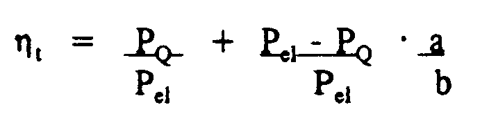
Dieser Wirkungsgrad (ηt) schließt auch die Verluste Pel - PQ mit in die Betrachtung ein und bewertet diese mit den Gestehungskosten der Energieeinheiten. Der Faktor a steht für die Gestehungskosten einer Energieeinheit aus Brennstoffen, der Faktor b für die Kosten der gleichen Energieeinheit aus elektrischem Strom. Da der Faktor b, der die Wärmeenergieerzeugung über den elektrischen Strom beinhaltet, immer größer ist als der Faktor a, wird der Quotient aus a und b stets kleiner als eins sein. Demnach ist ηt stets größer als η. Bei Heizungsanlagen, Pumpen für medizinische Bäder, Whirl-Pool-Pumpen und dergleichen kann somit der thermodynamisch-wirtschaftliche Wirkungsgrad des Pumpenaggregats durch die erfindungsgemäße Ausbildung erheblich gesteigert werden.With such pumps used in heat generation and heat distribution systems, it is not the otherwise usual hydraulic efficiency η that is decisive, but the thermodynamic-economic efficiency η t . Hydraulic efficiency η is the quotient of delivery capacity and electrical output.
(Q - flow rate, H - delivery head, ρ - density of the pumped medium, g - gravitational acceleration)
The thermodynamic-economic efficiency η t results as follows:
This efficiency (η t ) also includes the losses P el - P Q and evaluates them with the cost of the energy units. The factor a stands for the production costs of an energy unit from fuels, the factor b for the costs of the same energy unit from electric current. Since the factor b, which includes the generation of thermal energy via the electric current, is always greater than the factor a, the quotient of a and b will always be less than one. Accordingly, η t is always greater than η. In heating systems, pumps for medical baths, whirl pool pumps and the like, the thermodynamic-economic efficiency of the pump unit can thus be considerably increased by the design according to the invention.
Aber auch in anderen Fällen des Pumpeneinsatzes, bei denen eine Erwärmung des Fördermediums durch die elektrische Verlustwärme des Motors und des Frequenzumrichters keine Vorteile bringt, besteht der erhebliche Vorteil eines im Vergleich zum Stand der Technik kleineren und damit kostengünstigeren Motors dieses Pumpenaggregats, da die Reibungsverluste des Naßlaufmotors vermieden werden und die Pumpe mit hohen Drehzahlen betrieben werden kann.But also in other cases where the pump is used, in which heating of the pumped medium is not advantageous due to the electrical heat loss of the motor and the frequency converter, there is the considerable advantage of a smaller and therefore less expensive motor of this pump unit compared to the prior art, since the friction losses of the Wet running motor can be avoided and the pump can be operated at high speeds.
Fertigungstechnisch besonders günstig ist es, wenn der Kühlmantel aus tiefgezogenen und miteinander verschweißten Chromnickelstahlblechen hergestellt ist, die unter Ausbildung eines pumpenseitigen Flansches geformt und miteinander verbunden sind.In terms of production technology, it is particularly favorable if the cooling jacket is made from deep-drawn and welded chromium-nickel steel sheets, which are shaped and connected to one another to form a pump-side flange.
Einen guten Wärmeübergang zwischen Motor und Kühlmantel erreicht man dadurch, daß der Kühlmantel an seiner Innenseite zylindrisch zur Aufnahme des Statorblechpakets des Motors ausgebildet ist. Das Statorblechpaket kann in die Zylinderinnenwand des Kühlmantels eingepreßt sein, wodurch ein guter Wärmeübergang und mechanischer Verbund erreicht wird.Good heat transfer between the motor and the cooling jacket is achieved in that the cooling jacket is cylindrical on its inside for receiving the stator lamination stack of the motor. The stator laminated core can be pressed into the cylinder inner wall of the cooling jacket, as a result of which good heat transfer and mechanical bonding is achieved.
Um einen guten Wärmeübergang von den Verlustwärme erzeugenden Bauteilen des Frequenzumrichters zum Kühlmantel zu erzielen, ist es vorteilhaft, den Frequenzumrichter über einen Wärmeverteiler wärmeleitend an den Kühlmantel anzuschließen. Ein solcher Wärmeverteiler wird bevorzugt form- und kraftschlüssig am Außenumfang des Kühlmantels angebracht. Auf diese Weise kann der Freqzenzumrichter mit dem Wärmeverteiler als Baueinheit hergestellt und bei der Montage des Pumpenaggregats in einfacher Weise auf dem Kühlmantel befestigt werden.In order to achieve good heat transfer from the components of the frequency converter which generate heat loss to the cooling jacket, it is advantageous to connect the frequency converter to the cooling jacket in a heat-conducting manner via a heat distributor. Such a heat distributor is preferably attached to the outer circumference of the cooling jacket in a positive and non-positive manner. In this way, the frequency converter manufactured with the heat spreader as a structural unit and easily attached to the cooling jacket during assembly of the pump unit.
Der Kühlmantel weist an seinem pumpenseitigen Ende zweckmäßigerweise einen Flansch auf, mit dem er zwischen Motorgehäuse und Pumpengehäuse eingespannt werden kann. Auf diese Weise ergibt sich eine sehr einfache und zugleich stabile Befestigung des Kühlmantels innerhalb des Motorgehäuses.At its pump-side end, the cooling jacket expediently has a flange with which it can be clamped between the motor housing and the pump housing. This results in a very simple and at the same time stable attachment of the cooling jacket within the motor housing.
Das Motorgehäuse besteht bevorzugt aus einem kappenförmigen Teil sowie einem flanschartigen Teil, wobei sich das kappenförmige Teil an eine Stirnseite des flanschartigen Teils und das Pumpengehäuse an das andere stirnseitige Ende des flanschartigen Teils anschließt. Der Kühlmantel ist dann zwischen dem flanschartigen Teil und dem Pumpengehäuse eingespannt. Bei dieser Ausbildung kann das kappenförmige Teil des Motorgehäuses ohne Einfluß auf das übrige Pumpenaggregat montiert bzw. demontiert werden, so daß der Frequenzumrichter ohne weitere Demontage des Aggregats zugänglich ist.The motor housing preferably consists of a cap-shaped part and a flange-like part, the cap-shaped part adjoining one end of the flange-like part and the pump housing adjoining the other end of the flange-like part. The cooling jacket is then clamped between the flange-like part and the pump housing. With this design, the cap-shaped part of the motor housing can be assembled or disassembled without affecting the rest of the pump assembly, so that the frequency converter is accessible without further disassembly of the assembly.
Bevorzugt sind Ein- und Auslaßöffnungen für die den Kühlmantel durchströmende Förderflüssigkeit an der zur Pumpe gerichteten Stirnseite des Kühlmantels angeordnet. Hierdurch kann eine schraubenlinienförmige Durchströmung des Kühlmantels erreicht werden, wodurch eine genügende Verweildauer des Fördermediums innerhalb des Kühlmantels gewährleistet wird und somit die den Kühlmantel durchströmende Flüssigkeitsmenge und die damit verbundene hydraulische Verlustleistung gesenkt werden kann. Im übrigen gibt es bei dieser Ausbildung keine Dichtungsprobleme und keine flüssigkeitsführenden Anschlässe im Bereich des Motors bzw. des Motorgehäuses. Schließlich sorgt eine schraubenlinienförmige Durchströmung des Kühlmantels für eine schnelle und zuverlässige Abfuhr von im Kühlmantel befindlichem Gas, das die Kühlung stören könnte.Inlet and outlet openings for the conveying liquid flowing through the cooling jacket are preferably arranged on the end of the cooling jacket directed towards the pump. As a result, a helical flow through the cooling jacket can be achieved, as a result of which a sufficient residence time of the conveyed medium within the cooling jacket is ensured, and thus the amount of liquid flowing through the cooling jacket and the associated hydraulic power loss can be reduced. Moreover, there are no sealing problems with this design and no fluid-carrying connections in the area of the motor or the motor housing. Finally, a helical flow through the cooling jacket ensures rapid and reliable removal of gas in the cooling jacket, which could interfere with the cooling.
Zur Überwachung der Kühlfunktion ist es regelmäßig angebracht, eine Temperaturmeßeinrichtung vorzusehen. Über eine entsprechende Sicherheitssteuerung kann mit Hilfe einer solchen Temperaturmeßeinrichtung eine thermische Überlastung des Aggregats verhindert werden. Bei der erfindungsgemäßen Konstruktion ist es von Vorteil, diese Temperaturmeßeinrichtung, insbesondere den Meßfühler dieser Einrichtung, an der Außenseite des Kühlmantels oder des Wärmeverteilers anzuordnen. Diese Anordnung berücksichtigt die Erwärmung in Abhängigkeit der Kühlung, d.h., die Meßeinrichtung erfaßt sowohl eine übermäßige Erwärmung des Frequenzumrichters durch elektrische Überlastung, beispielsweise bei Defekt von Bauelementen, als auch einen Ausfall des Kühlmittelstroms durch den Kühlmantel.To monitor the cooling function, it is regularly appropriate to provide a temperature measuring device. Such a temperature measuring device can be used to prevent thermal overloading of the unit via an appropriate safety control. In the construction according to the invention, it is advantageous to use this temperature measuring device, in particular the sensor of this device, to be arranged on the outside of the cooling jacket or the heat distributor. This arrangement takes into account the heating as a function of the cooling, ie the measuring device detects both excessive heating of the frequency converter due to electrical overload, for example in the event of component defects, and a failure of the coolant flow through the cooling jacket.
Die Erfindung ist nachfolgend anhand einer in den Zeichnungen dargestellten Whirl-Pool-Pumpe beschrieben. Es zeigen:
- Figur 1
- einen Längsschnitt durch ein Pumpenaggregat in stark vereinfachter Darstellung und
- Figur 2
- eine Ansicht in Richtung des Pfeils II in Figur 1 nach Entfernen der Motorgehäusekappe.
- Figure 1
- a longitudinal section through a pump unit in a greatly simplified representation and
- Figure 2
- a view in the direction of arrow II in Figure 1 after removal of the motor housing cap.
Bei dem dargestellten Pumpenaggregat handelt es sich um eine Whirl-Pool-Pumpe. Das Pumpengehäuse 1 weist einen Einlaßstutzen 2 sowie einen Auslaßstutzen 3 auf. Zwischen Ein- und Auslaßstutzen 2,3 befindet sich ein Kreiselrad 4, das bei Rotation in bekannter Weise einen Förderstrom erzeugt.The pump unit shown is a whirl pool pump. The pump housing 1 has an inlet connector 2 and an outlet connector 3. Between the inlet and outlet port 2, 3 there is a rotary wheel 4 which generates a flow in a known manner when rotating.
Das Kreiselrad 4 sitzt innerhalb des Pumpengehäuses 1 auf einem Ende einer Welle 5, die den Rotor 6 eines Elektromotors 7 trägt. Die Welle 5 ist gegenüber dem Pumpengehäuse 1 abgedichtet und am motorseitigen Ende in einem Lager 8 sowie nahe dem pumpenseitigen Ende in einem Lager 9 gelagert.The impeller 4 sits inside the pump housing 1 on one end of a shaft 5 which carries the rotor 6 of an electric motor 7. The shaft 5 is sealed off from the pump housing 1 and is mounted in a bearing 8 at the motor end and in a bearing 9 near the pump end.
Der Rotor 6 des Elektromotors 7 ist somit ebenfalls über die Lager 8,9 gelagert und rotiert innerhalb eines Stators 10, dessen zylindrischer Außenumfang (Statorblechpaket) innerhalb eines Kühlmantels 11 sitzt. Die innerhalb des Stators 10 verlaufende Motorwicklung ist mit 12 gekennzeichnet.The rotor 6 of the electric motor 7 is thus also supported via the bearings 8, 9 and rotates within a
Der Kühlmantel 11 besteht aus einem zylindrischen, topfförmigen Teil 13, das an seinem offenen Ende hin zu einem stufenförmigen Flansch ausgebildet ist. Dieser topfförmige Teil 13 wird umfangseitig von einem ringförmigen, sich vom topfförmigen Teil 13 erhebenden Teil 14 umgeben, welches zum offenen Ende des topfförmigen Teils 13 erweiternd ebenfalls in einen Flansch ausläuft. Die Flansche der Teile 13 und 14 sind zu einem gemeinsamen Flansch 15 dicht, beispielsweise durch Schweißen, miteinander verbunden.The cooling
Zwischen den Teilen 13 und 14 des Kühlmantels 11 ist ein Ringraum gebildet, der zwei, etwa diametral angeordnete (nicht dargestellte) Öffnungen zum Pumpengehäuse 1 hin aufweist, die jeweils eine Verbindung zum Förderstrom der Pumpe bilden, wobei diese Öffnungen in Bereichen unterschiedlichen Druckniveaus der Pumpe liegen, so daß bei Förderung der Pumpe ein Teil des Förderstroms als Kühlstrom durch den Kühlmantel 11 gelangt.Between the
An der ebenfalls zylindrischen Außenseite des Kühlmantels 11 (insbesondere des ringförmigen Teiles 14) ist über einen Wärmeverteiler 16 ein Frequenzumrichter 17 wärmeleitend mit dem Kühlmantel 11 verbunden. Der Frequenzumrichter 17 mit seinen Verlustwärme erzeugenden elektronischen Bauelementen ist in an sich bekannter Weise so angeordnet und ausgebildet, daß die Verlustwärme über den Wärmeverteiler 16 zum Kühlmantel 11 geleitet wird. Wärmeverteiler 16 und Frequenzumrichter 17 sind als Baueinheit ausgebildet und form- und kraftschlüssig am Außenumfang des Kühlmantels 11 angebracht. Dies kann beispielsweise über die in Figur 2 mit 18 angedeuteten Federzungen erfolgen, die entweder um die Unterseite des Kühlmantels 11 umlaufend ausgebildet oder seitlich an diesem angeschweißt sind. Diese Federzungen 18 rasten form- und kraftschlüssig hinter entsprechenden Vorsprüngen an den Längsseiten des Wärmeverteilers 16 ein und drücken diesen zum Kühlmantel 11 hin. Derartige Verbindungen sind hinreichend bekannt.On the likewise cylindrical outside of the cooling jacket 11 (in particular the annular part 14), a frequency converter 17 is connected in a heat-conducting manner to the cooling
Am Beden des topfförmigen Teils 13 ist an der Innenseite eine Aufnahme 20 für das Lager 8 vorgesehen. Nahe dem offenen Ende des Kühlmantels 11 ist innerhalb des topfförmigen Teils 13 eine ringförmige, aus Blech geformte Lageraufnahme 21 eingelassen, die im wesentlichen scheibenförmig ausgebildet ist und einen umfangseitigen Kragen zum Anschluß an den topfförmigen Teil 13 sowie eine mittige Einformung zur Aufnahme des Lagers 9 aufweist. Zur Durchführung der Welle 5 ist diese scheibenförmige Lageraufnahme 11 mittig durchbrochen.At the bed of the pot-shaped
Der Kühlmantel 11 nimmt innenseitig den Motor 7, außenseitig sitzt der Frequenzumrichter 17. Zur Pumpe hin ist der Kühlmantel 11 durch einen inneren Teil des Pumpengehäuses 1 abgestützt, wie sich aus Figur 1 ergibt. Gehalten wird der Kühlmantel 11 sowie die davon getragenen Aggregatteile an dem Flansch 15, der zwischen dem Pumpengehäuse 1 und einem flanschartigen Gehäuseteil 22 eingespannt ist. Das flanschartige Gehäuseteil 22 liegt nicht nur stirnseitig an dem Flansch 15 des Kühlmantels 11 an, sondern führt diesen im Bereich vor dem Flansch 15 auch radial. An diesen rohrförmigen Teil des flanschartigen Gehäuseteils 22 schließt sich in Richtung zum Motor hin ein schräg aufgeweitetes Flanschteil an, das stirnseitig zur Verbindung mit einer das Gehäuse nach hinten dichtend abschließenden Gehäusekappe 23 vorgesehen ist. Die Gehäusekappe 23 ist, wie in Figur 1 dargestellt, etwa topfartig ausgebildet und umschließt nahezu den gesamten Kühlmantel 11 sowie den darauf sitzenden Wärmeverteiler 16 mit Frequenzumrichter 17 mit Abstand.The cooling
An der Unterseite des Motorengehäuses 22, 23 ist ein Fuß 24 angeordnet, der in Achsrichtung des Aggregates verschiebbar ist.On the underside of the
Innerhalb des Wärmeverteilers 16 ist eine Temperaturmeßeinrichtung zur Überwachung der Kühlleistung angeordnet. Diese, in der Zeichnung nicht dargestellte Temperaturmeßeinrichtung kann auch an der Außenseite des Kühlmantels 11 angebracht sein.A temperature measuring device for monitoring the cooling capacity is arranged within the
Claims (9)
Applications Claiming Priority (2)
| Application Number | Priority Date | Filing Date | Title |
|---|---|---|---|
| DE4121430A DE4121430C1 (en) | 1991-06-28 | 1991-06-28 | |
| DE4121430 | 1991-06-28 |
Publications (2)
| Publication Number | Publication Date |
|---|---|
| EP0520333A1 true EP0520333A1 (en) | 1992-12-30 |
| EP0520333B1 EP0520333B1 (en) | 1995-10-04 |
Family
ID=6434993
Family Applications (1)
| Application Number | Title | Priority Date | Filing Date |
|---|---|---|---|
| EP92110380A Expired - Lifetime EP0520333B1 (en) | 1991-06-28 | 1992-06-19 | Pump unit |
Country Status (3)
| Country | Link |
|---|---|
| US (1) | US5332369A (en) |
| EP (1) | EP0520333B1 (en) |
| DE (2) | DE4121430C1 (en) |
Cited By (1)
| Publication number | Priority date | Publication date | Assignee | Title |
|---|---|---|---|---|
| EP0639715A1 (en) * | 1993-08-18 | 1995-02-22 | Grundfos A/S | Device for the supply of liquid |
Families Citing this family (58)
| Publication number | Priority date | Publication date | Assignee | Title |
|---|---|---|---|---|
| DE4222394C1 (en) * | 1992-07-08 | 1993-12-09 | Grundfos A S Bjerringbro | Electric pump unit with cooled frequency regulator - has power stage of frequency regulator mounted on cooling wall between spiral pump housing and electric motor |
| DE4238925A1 (en) * | 1992-11-19 | 1994-05-26 | Teves Gmbh Alfred | Electric motor with cooled outer wall - consisting of metallic material with which brushes of one polarity arranged on inner side are in direct contact |
| DE4319618A1 (en) * | 1993-06-14 | 1994-12-15 | Wilo Gmbh | Submersible motor-driven pump |
| DE4319619A1 (en) * | 1993-06-14 | 1994-12-15 | Wilo Gmbh | Submersible pump |
| JP3077490B2 (en) * | 1993-12-28 | 2000-08-14 | 株式会社荏原製作所 | Pump assembly |
| JPH0861287A (en) * | 1994-08-11 | 1996-03-08 | Ebara Corp | Inverter unit for pump and pump device having this unit |
| DE4438130A1 (en) * | 1994-10-27 | 1996-05-02 | Wilo Gmbh | Canned motor |
| DE19510774C2 (en) * | 1995-03-24 | 1997-09-11 | Hanning Elektro Werke | Cooling device for electronic components |
| US5549447A (en) * | 1995-08-21 | 1996-08-27 | Mcneil (Ohio) Corporation | System for cooling a centrifugal pump |
| US5700138A (en) * | 1995-08-21 | 1997-12-23 | Mcneil (Ohio) Corporation | Centrifugal pump |
| DE19652706A1 (en) * | 1995-12-22 | 1997-06-26 | Rexroth Mannesmann Gmbh | Compact hydraulic unit with hydro-pump driven by air-cooled electric motor |
| DE19624145A1 (en) * | 1996-06-18 | 1998-01-08 | Wilo Gmbh | Electric motor |
| DE19639098A1 (en) * | 1996-09-24 | 1998-03-26 | Wilo Gmbh | Motor pump with cooled frequency converter |
| DE19700965C1 (en) * | 1997-01-14 | 1998-06-04 | Grundfos As | Sensor arrangement |
| US5930852A (en) * | 1997-03-21 | 1999-08-03 | Aqua-Flo, Incorporated | Heat exchanging pump motor for usage within a recirculating water system |
| US5997261A (en) * | 1997-10-31 | 1999-12-07 | Siemens Canada Limited | Pump motor having fluid cooling system |
| EP0913582B1 (en) * | 1997-10-31 | 2003-09-24 | Siemens VDO Automotive Inc. | Pump motor having sumbersible stator and rotor |
| DE19856096A1 (en) * | 1997-12-23 | 1999-06-24 | Mannesmann Rexroth Ag | Driver for pump for adjustable drive for a hydraulic pump |
| EP1061258A4 (en) * | 1998-03-04 | 2007-01-10 | Ebara Corp | Performance regulating device for fluid machinery |
| JPH11334616A (en) * | 1998-05-21 | 1999-12-07 | Koyo Seiko Co Ltd | Power steering unit |
| JP4138111B2 (en) * | 1998-06-18 | 2008-08-20 | アスモ株式会社 | Fluid pump device |
| DE59908003D1 (en) * | 1998-09-15 | 2004-01-22 | Wilo Ag | tube pump |
| DE19903951B4 (en) * | 1999-02-02 | 2013-11-14 | Fritz Eichenauer Gmbh & Co. Kg | Heatable pump housing for liquid heating |
| DE19904148C1 (en) | 1999-02-03 | 2000-10-12 | Pierburg Ag | Electric feed pump |
| EP1150883B1 (en) * | 1999-02-12 | 2003-04-23 | Siemens Aktiengesellschaft | Electric ship propulsion |
| US6227819B1 (en) | 1999-03-29 | 2001-05-08 | Walbro Corporation | Fuel pumping assembly |
| US6231318B1 (en) | 1999-03-29 | 2001-05-15 | Walbro Corporation | In-take fuel pump reservoir |
| DE19943577A1 (en) * | 1999-09-13 | 2001-03-15 | Wilo Gmbh | Pump housing with integrated electronics |
| US6314749B1 (en) * | 2000-02-03 | 2001-11-13 | Leon R. Van Steenburgh, Jr. | Self-clearing vacuum pump with external cooling for evacuating refrigerant storage devices and systems |
| US6554586B1 (en) * | 2000-03-30 | 2003-04-29 | Ferdinand Lustwerk | Sealed motor driven centrifugal primary fluid pump with secondary fluid flow for cooling primary fluid |
| US6722854B2 (en) | 2001-01-24 | 2004-04-20 | Sundyne Corporation | Canned pump with ultrasonic bubble detector |
| AUPR369901A0 (en) * | 2001-03-13 | 2001-04-12 | Davey Products Pty Ltd | Improved pump |
| EP1260714B1 (en) * | 2001-05-25 | 2006-11-29 | Grundfos A/S | Pump unit with drive motor and submersible pump |
| US6685447B2 (en) * | 2002-01-25 | 2004-02-03 | Hamilton Sundstrand | Liquid cooled integrated rotordynamic motor/generator station with sealed power electronic controls |
| GB2388404B (en) * | 2002-05-09 | 2005-06-01 | Dana Automotive Ltd | Electric pump |
| US20060034717A1 (en) * | 2004-08-13 | 2006-02-16 | Joseph Castellone | Wet rotor circulators |
| DE102008057414B3 (en) * | 2008-11-14 | 2010-07-08 | Aoa Apparatebau Gauting Gmbh | Delivery device, particularly high speed delivery device for liquid media, particularly explosive liquids, has electric motor, pump rotor, pump housing and electronic power control system |
| DE102009010461A1 (en) | 2009-02-13 | 2010-08-19 | Alfred Kärcher Gmbh & Co. Kg | Motor pump unit |
| EP2396545A1 (en) * | 2009-02-13 | 2011-12-21 | Alfred Kärcher GmbH & Co. KG | Motor pump unit |
| DK2227078T3 (en) * | 2009-03-04 | 2012-02-20 | Ebm Papst Mulfingen Gmbh & Co | Clamping component for pressing performance components to a cooling surface |
| CN101871459B (en) * | 2009-04-24 | 2013-10-30 | 德昌电机(深圳)有限公司 | Discharge pump |
| US8840380B2 (en) | 2011-01-21 | 2014-09-23 | Toyota Motor Engineering & Manufacturing North America, Inc. | Temperature control ring for vehicle air pump |
| US8558421B2 (en) | 2011-07-27 | 2013-10-15 | General Electric Compant | Shaft mounted geared fan for operating motors and method of assembling such motors |
| US8704414B2 (en) | 2011-09-14 | 2014-04-22 | General Electric Company | Machines and methods and assembly for same |
| US20130189131A1 (en) * | 2012-01-19 | 2013-07-25 | Han-Lung Huang | Water cooled motor with stainless steel cooling jacket |
| DE112013001169T5 (en) * | 2012-02-27 | 2014-12-11 | Magna Powertrain Of America, Inc. | Electric motor driven pump |
| ITPD20120409A1 (en) * | 2012-12-27 | 2014-06-28 | Dab Pumps Spa | LIQUID FLOW RATE CONTROL EQUIPMENT OF A ELECTRIC PUMP AND THE ELECTRONIC CONTROL TEMPERATURE AND COMMAND OF A PUMPING DEVICE PROVIDING THE ELECTRIC PUMP |
| CN104405646A (en) * | 2014-11-05 | 2015-03-11 | 天津知远义信科技咨询有限公司 | Novel supercharging water pump |
| ITUB20160314A1 (en) * | 2016-02-02 | 2017-08-02 | Dab Pumps Spa | PERFECT STRUCTURE OF CENTRIFUGAL ELECTRIC PUMP AND MOTOR CASE FOR THIS PERFECT STRUCTURE |
| KR102333614B1 (en) | 2016-07-20 | 2021-12-01 | 스택폴 인터내셔널 엔지니어드 프로덕츠, 엘티디. | Pump assembly with integrated controller and motor with internal active cooling |
| US10784750B2 (en) | 2018-06-12 | 2020-09-22 | General Electric Company | Electric motor having an integrated cooling system and methods of cooling an electric motor |
| US11146133B2 (en) | 2018-08-30 | 2021-10-12 | General Electric Company | Electric machine with rotor coolant and lubrication distribution system, and systems and methods of cooling and lubricating an electric machine |
| CN111120409B (en) * | 2018-10-31 | 2023-06-06 | 杭州三花研究院有限公司 | Electronic water pump |
| US20200309153A1 (en) * | 2019-03-25 | 2020-10-01 | Pentair Water Pool And Spa, Inc. | Water cooled pump system |
| CN110225692A (en) * | 2019-06-19 | 2019-09-10 | 绵阳富临精工机械股份有限公司 | A kind of controller radiator structure and electronic water pump heat dissipating method |
| IT202000004870A1 (en) * | 2020-03-09 | 2021-09-09 | Dab Pumps Spa | ELECTRONIC PUMP WITH PERFECT INSULATION OF THE ELECTRONIC PART AND HEAT SINK ELEMENT FOR THIS ELECTRONIC PART |
| DE102020006366A1 (en) | 2020-10-16 | 2022-04-21 | KSB SE & Co. KGaA | Centrifugal pump with a drive |
| EP4240977A1 (en) * | 2020-11-04 | 2023-09-13 | Gecko Alliance Group Inc. | Water-cooled pump assembly for bathing unit system and pump assembly for bathing unit system with mounting brackets |
Citations (4)
| Publication number | Priority date | Publication date | Assignee | Title |
|---|---|---|---|---|
| FR2082048A5 (en) * | 1970-03-02 | 1971-12-10 | Hobson Ltd | |
| FR2608332A1 (en) * | 1986-12-13 | 1988-06-17 | Grundfos Int | ELECTRIC MOTOR WITH FREQUENCY CONVERTER FOR ADJUSTING ENGINE OPERATING PARAMETERS |
| GB2199081A (en) * | 1986-12-13 | 1988-06-29 | Grundfos Int | Pump assembly |
| DE3738592C1 (en) * | 1987-11-13 | 1989-05-24 | Licentia Gmbh | Electric motor for driving a liquid pump, and a method for its production |
Family Cites Families (10)
| Publication number | Priority date | Publication date | Assignee | Title |
|---|---|---|---|---|
| US2784672A (en) * | 1954-03-15 | 1957-03-12 | Us Electrical Motors Inc | Fluid pump drive |
| GB1187866A (en) * | 1967-11-16 | 1970-04-15 | Sealed Motor Const Co Ltd | Improvements in and relating to Electric Motorised Centrifugal Pumps. |
| DE2743112A1 (en) * | 1977-09-24 | 1979-04-05 | Albert Blum | Electrically driven pump assembly - has motor housing formed of synthetic plastics and corrosion proof steel to resist heat influence |
| US4213745A (en) * | 1978-09-11 | 1980-07-22 | Roberts Samuel A | Pump for central heating system |
| DE3105389C2 (en) * | 1981-02-14 | 1984-12-20 | Grundfos A/S, Bjerringbro | Canned motor pump |
| JPH0442559Y2 (en) * | 1985-10-03 | 1992-10-07 | ||
| DE3642727A1 (en) * | 1986-12-13 | 1988-06-23 | Grundfos Int | Underwater motor-driven pump |
| IT8747731A0 (en) * | 1987-03-16 | 1987-03-16 | Stanzani Franco | MOTOR COMPRESSOR GROUP STRUCTURE FOR REFRIGERANTS |
| DE3820005C1 (en) * | 1988-06-11 | 1989-10-05 | Grundfos International A/S, Bjerringbro, Dk | |
| US4998865A (en) * | 1988-07-11 | 1991-03-12 | Aisan Kogyo Kabushiki Kaisha | Brushless DC pump with enclosed circuit board |
-
1991
- 1991-06-28 DE DE4121430A patent/DE4121430C1/de not_active Expired - Lifetime
-
1992
- 1992-06-19 EP EP92110380A patent/EP0520333B1/en not_active Expired - Lifetime
- 1992-06-19 DE DE59203881T patent/DE59203881D1/en not_active Expired - Lifetime
- 1992-06-26 US US07/904,786 patent/US5332369A/en not_active Expired - Lifetime
Patent Citations (4)
| Publication number | Priority date | Publication date | Assignee | Title |
|---|---|---|---|---|
| FR2082048A5 (en) * | 1970-03-02 | 1971-12-10 | Hobson Ltd | |
| FR2608332A1 (en) * | 1986-12-13 | 1988-06-17 | Grundfos Int | ELECTRIC MOTOR WITH FREQUENCY CONVERTER FOR ADJUSTING ENGINE OPERATING PARAMETERS |
| GB2199081A (en) * | 1986-12-13 | 1988-06-29 | Grundfos Int | Pump assembly |
| DE3738592C1 (en) * | 1987-11-13 | 1989-05-24 | Licentia Gmbh | Electric motor for driving a liquid pump, and a method for its production |
Cited By (1)
| Publication number | Priority date | Publication date | Assignee | Title |
|---|---|---|---|---|
| EP0639715A1 (en) * | 1993-08-18 | 1995-02-22 | Grundfos A/S | Device for the supply of liquid |
Also Published As
| Publication number | Publication date |
|---|---|
| DE4121430C1 (en) | 1992-11-05 |
| EP0520333B1 (en) | 1995-10-04 |
| US5332369A (en) | 1994-07-26 |
| DE59203881D1 (en) | 1995-11-09 |
Similar Documents
| Publication | Publication Date | Title |
|---|---|---|
| EP0520333B1 (en) | Pump unit | |
| EP0346730B1 (en) | Submersible pump assembly | |
| DE102011001041B9 (en) | Magnetically driven pump arrangement with a micropump with forced flushing and working method | |
| EP0493704B1 (en) | Electric motor | |
| EP0660492B1 (en) | Cooling system for a motor | |
| EP1256722B1 (en) | Centrifugal pump | |
| EP1502030A1 (en) | Driving motor, especially for a pump | |
| AT502566A1 (en) | WATER PUMP | |
| EP2566015B1 (en) | Electric motor | |
| EP0831236B2 (en) | Motor pump with cooled frequency converter | |
| WO2002100672A1 (en) | Hybrid drive system comprising a torque converter | |
| EP2072825A2 (en) | Coolant pump | |
| EP1910685B1 (en) | Electric motor having a coaxially arranged pump | |
| EP0688090B1 (en) | Motor cooling system | |
| EP3759356A1 (en) | Electric coolant pump | |
| DE2307800B2 (en) | Brushless DC motor for high speeds | |
| WO2007054169A1 (en) | Fluid pump | |
| DE202005013923U1 (en) | Installation for feed of fluids has rotor of motor connected to second permanent magnet which interacts with first permanent magnet connected to pump wheel in fashion of magnetic clutch | |
| EP1179141B1 (en) | Device, especially canned motor, for converting electrical energy into mechanical energy and/or vice versa | |
| DE102004047637B4 (en) | Electrically operated pump with external rotor | |
| DE102004047635B4 (en) | Electrically operated pump with internal rotor | |
| DE10312978A1 (en) | Electro-hydrodynamic unit e.g. fluid pump or heating pump, has radial struts formed as vanes or blades for forming the fluid pressure generator | |
| DE102006027566A1 (en) | External rotor motor | |
| DE102022003732A1 (en) | Pump for pumping cooled liquid gas from a first container to a second container | |
| DE19803739A1 (en) | Glandless cooling water circulation pump |
Legal Events
| Date | Code | Title | Description |
|---|---|---|---|
| PUAI | Public reference made under article 153(3) epc to a published international application that has entered the european phase |
Free format text: ORIGINAL CODE: 0009012 |
|
| AK | Designated contracting states |
Kind code of ref document: A1 Designated state(s): DE FR GB IT |
|
| 17P | Request for examination filed |
Effective date: 19930611 |
|
| 17Q | First examination report despatched |
Effective date: 19950109 |
|
| GRAA | (expected) grant |
Free format text: ORIGINAL CODE: 0009210 |
|
| AK | Designated contracting states |
Kind code of ref document: B1 Designated state(s): DE FR GB IT |
|
| REF | Corresponds to: |
Ref document number: 59203881 Country of ref document: DE Date of ref document: 19951109 |
|
| ITF | It: translation for a ep patent filed |
Owner name: FUMERO BREVETTI S.N.C. |
|
| GBT | Gb: translation of ep patent filed (gb section 77(6)(a)/1977) |
Effective date: 19951216 |
|
| ET | Fr: translation filed | ||
| PLBQ | Unpublished change to opponent data |
Free format text: ORIGINAL CODE: EPIDOS OPPO |
|
| PLBI | Opposition filed |
Free format text: ORIGINAL CODE: 0009260 |
|
| PLBQ | Unpublished change to opponent data |
Free format text: ORIGINAL CODE: EPIDOS OPPO |
|
| PLAB | Opposition data, opponent's data or that of the opponent's representative modified |
Free format text: ORIGINAL CODE: 0009299OPPO |
|
| PLBF | Reply of patent proprietor to notice(s) of opposition |
Free format text: ORIGINAL CODE: EPIDOS OBSO |
|
| 26 | Opposition filed |
Opponent name: WILO GMBH Effective date: 19960704 |
|
| R26 | Opposition filed (corrected) |
Opponent name: WILO GMBH Effective date: 19960704 |
|
| PLBF | Reply of patent proprietor to notice(s) of opposition |
Free format text: ORIGINAL CODE: EPIDOS OBSO |
|
| PLBF | Reply of patent proprietor to notice(s) of opposition |
Free format text: ORIGINAL CODE: EPIDOS OBSO |
|
| PLBO | Opposition rejected |
Free format text: ORIGINAL CODE: EPIDOS REJO |
|
| PLBN | Opposition rejected |
Free format text: ORIGINAL CODE: 0009273 |
|
| STAA | Information on the status of an ep patent application or granted ep patent |
Free format text: STATUS: OPPOSITION REJECTED |
|
| 27O | Opposition rejected |
Effective date: 19981130 |
|
| REG | Reference to a national code |
Ref country code: GB Ref legal event code: IF02 |
|
| PLAB | Opposition data, opponent's data or that of the opponent's representative modified |
Free format text: ORIGINAL CODE: 0009299OPPO |
|
| PGFP | Annual fee paid to national office [announced via postgrant information from national office to epo] |
Ref country code: FR Payment date: 20110610 Year of fee payment: 20 |
|
| PGFP | Annual fee paid to national office [announced via postgrant information from national office to epo] |
Ref country code: GB Payment date: 20110628 Year of fee payment: 20 |
|
| PGFP | Annual fee paid to national office [announced via postgrant information from national office to epo] |
Ref country code: IT Payment date: 20110608 Year of fee payment: 20 |
|
| PGFP | Annual fee paid to national office [announced via postgrant information from national office to epo] |
Ref country code: DE Payment date: 20110801 Year of fee payment: 20 |
|
| REG | Reference to a national code |
Ref country code: DE Ref legal event code: R071 Ref document number: 59203881 Country of ref document: DE |
|
| REG | Reference to a national code |
Ref country code: DE Ref legal event code: R071 Ref document number: 59203881 Country of ref document: DE |
|
| REG | Reference to a national code |
Ref country code: GB Ref legal event code: PE20 Expiry date: 20120618 |
|
| PG25 | Lapsed in a contracting state [announced via postgrant information from national office to epo] |
Ref country code: DE Free format text: LAPSE BECAUSE OF EXPIRATION OF PROTECTION Effective date: 20120620 |
|
| PG25 | Lapsed in a contracting state [announced via postgrant information from national office to epo] |
Ref country code: GB Free format text: LAPSE BECAUSE OF EXPIRATION OF PROTECTION Effective date: 20120618 |