EP0658721B1 - Lighting device - Google Patents
Lighting device Download PDFInfo
- Publication number
- EP0658721B1 EP0658721B1 EP94119788A EP94119788A EP0658721B1 EP 0658721 B1 EP0658721 B1 EP 0658721B1 EP 94119788 A EP94119788 A EP 94119788A EP 94119788 A EP94119788 A EP 94119788A EP 0658721 B1 EP0658721 B1 EP 0658721B1
- Authority
- EP
- European Patent Office
- Prior art keywords
- illuminating device
- light
- light source
- reflecting surface
- reflector
- Prior art date
- Legal status (The legal status is an assumption and is not a legal conclusion. Google has not performed a legal analysis and makes no representation as to the accuracy of the status listed.)
- Expired - Lifetime
Links
Images


Classifications
-
- F—MECHANICAL ENGINEERING; LIGHTING; HEATING; WEAPONS; BLASTING
- F21—LIGHTING
- F21V—FUNCTIONAL FEATURES OR DETAILS OF LIGHTING DEVICES OR SYSTEMS THEREOF; STRUCTURAL COMBINATIONS OF LIGHTING DEVICES WITH OTHER ARTICLES, NOT OTHERWISE PROVIDED FOR
- F21V7/00—Reflectors for light sources
- F21V7/10—Construction
- F21V7/16—Construction with provision for adjusting the curvature
-
- F—MECHANICAL ENGINEERING; LIGHTING; HEATING; WEAPONS; BLASTING
- F21—LIGHTING
- F21V—FUNCTIONAL FEATURES OR DETAILS OF LIGHTING DEVICES OR SYSTEMS THEREOF; STRUCTURAL COMBINATIONS OF LIGHTING DEVICES WITH OTHER ARTICLES, NOT OTHERWISE PROVIDED FOR
- F21V14/00—Controlling the distribution of the light emitted by adjustment of elements
- F21V14/04—Controlling the distribution of the light emitted by adjustment of elements by movement of reflectors
-
- F—MECHANICAL ENGINEERING; LIGHTING; HEATING; WEAPONS; BLASTING
- F21—LIGHTING
- F21V—FUNCTIONAL FEATURES OR DETAILS OF LIGHTING DEVICES OR SYSTEMS THEREOF; STRUCTURAL COMBINATIONS OF LIGHTING DEVICES WITH OTHER ARTICLES, NOT OTHERWISE PROVIDED FOR
- F21V7/00—Reflectors for light sources
- F21V7/0008—Reflectors for light sources providing for indirect lighting
-
- F—MECHANICAL ENGINEERING; LIGHTING; HEATING; WEAPONS; BLASTING
- F21—LIGHTING
- F21V—FUNCTIONAL FEATURES OR DETAILS OF LIGHTING DEVICES OR SYSTEMS THEREOF; STRUCTURAL COMBINATIONS OF LIGHTING DEVICES WITH OTHER ARTICLES, NOT OTHERWISE PROVIDED FOR
- F21V7/00—Reflectors for light sources
- F21V7/10—Construction
- F21V7/18—Construction with provision for folding or collapsing
-
- G—PHYSICS
- G01—MEASURING; TESTING
- G01N—INVESTIGATING OR ANALYSING MATERIALS BY DETERMINING THEIR CHEMICAL OR PHYSICAL PROPERTIES
- G01N21/00—Investigating or analysing materials by the use of optical means, i.e. using sub-millimetre waves, infrared, visible or ultraviolet light
- G01N21/84—Systems specially adapted for particular applications
- G01N21/88—Investigating the presence of flaws or contamination
- G01N21/8806—Specially adapted optical and illumination features
-
- F—MECHANICAL ENGINEERING; LIGHTING; HEATING; WEAPONS; BLASTING
- F21—LIGHTING
- F21V—FUNCTIONAL FEATURES OR DETAILS OF LIGHTING DEVICES OR SYSTEMS THEREOF; STRUCTURAL COMBINATIONS OF LIGHTING DEVICES WITH OTHER ARTICLES, NOT OTHERWISE PROVIDED FOR
- F21V11/00—Screens not covered by groups F21V1/00, F21V3/00, F21V7/00 or F21V9/00
- F21V11/16—Screens not covered by groups F21V1/00, F21V3/00, F21V7/00 or F21V9/00 using sheets without apertures, e.g. fixed
- F21V11/18—Screens not covered by groups F21V1/00, F21V3/00, F21V7/00 or F21V9/00 using sheets without apertures, e.g. fixed movable, e.g. flaps, slides
Definitions
- the invention relates to a lighting device, in particular for use in quality control processes, with at least one light source, at least one deflection reflector and at least one reflection surface.
- the light source, the deflecting reflectors and the reflecting surface must be optimally aligned with one another and the deflecting reflectors and in particular the reflecting surface must be set exactly.
- Such installations are very complex and are arranged in the area of the production lines as a fixed installation.
- a disadvantage of this known device is that the installation of the components must be planned with great care. Already Small errors in the pre-installation of the holding devices, for example, can lead to unusable lighting conditions. Due to the fixed installation, the known lighting device is very complex and costly, both with regard to the parts used and with regard to the assembly. Finally, the previously known lighting device is susceptible to failure, since in particular the light source and the associated deflecting reflectors are arranged in the production or work area and can easily be inadvertently adjusted. Because of the distance between the lighting device and the light sail, the lighting conditions can be adversely affected. However, since it is important for the desired visual quality controls that the beam path of the light is precisely defined, that is to say that light mixing, parallelism and the like are clearly defined, such disturbances can affect the entire production.
- the object of the invention is to improve a lighting device of the generic type in such a way that it can be produced and / or installed with little economic outlay, can be easily set up, is variable with regard to the place of use and is generally not susceptible to faults.
- the generic lighting device is improved in that the at least one light source, at least one deflecting reflector and at least one reflecting surface are connected to each other to form an assembly.
- the lighting device according to the invention makes it possible for the light source, the deflection reflector and the reflection surface to be aligned with one another in a basic setting, in order then to be arranged as a uniform assembly relative to the area to be monitored. This considerably simplifies the installation of the lighting device and thus makes the use of such devices more economical. Furthermore, all components of the device can be arranged in an area that is not susceptible to faults relative to the area to be monitored.
- the light source is advantageously a luminaire with a housing with a substantially rectangular front.
- the deflection reflector is on the light source housing arranged in the area of the front surface.
- the deflection reflector can then have the shape desired for the intended use, so that the desired lighting can be achieved.
- the reflection surface is arranged within the deflection reflector, the entire lighting device has a one-piece character, the luminaire housing being enlarged by the deflection reflector and the required reflection surfaces being arranged in the deflection reflector.
- the light source can expediently be provided with at least one filter which is arranged in the beam path. The quality, the radiation area and possibly also the polarization of the light can be specified by the corresponding filters.
- the reflector surface is advantageously a light sail, which advantageously consists of individual reflector lamellae. In this way, the entire light sail can advantageously be adjustable, or, additionally or alternatively, individual reflector slats can also be adjusted.
- an adjustable cover flap is arranged in the deflection reflector opposite the light sail. This allows the radiation path of the light to be limited and adjusted.
- the unit light source, deflecting reflector and reflection surface are arranged on a supporting frame.
- a supporting structure can be provided with fastening devices in order to ensure simple fastening in the surveillance area.
- the switch cabinet required for the lighting operation is arranged on the support frame, in which a dimmer device is advantageously accommodated.
- the number of light sources, the deflecting reflectors and the reflecting surfaces depend on the desired range of applications. Due to the integrated design, the lighting device according to the invention can be used with a few Components can be manufactured and set up inexpensively. In addition, the use of the device is highly variable and only slightly susceptible to faults.
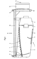
- the lighting device 1 comprises a lamp 2, a deflection reflector 3 and a reflection surface 4.
- the deflection reflector 3 is fastened to the connection 2 5 on the lamp 2.
- the reflection surface 4 is in turn attached to the deflection reflector 3 and adjustable via an adjustment mimic 6.
- the reflection surface 4 consists of individual reflection slats 7, which in turn are adjustable relative to one another.
- a dimming flap 8 is arranged on the deflection reflector, which can be rotatably supported on one side by means of an adjustment mimic 9 relative to the beam path.
- the assembly consisting of lamp 2, deflecting reflector 3, reflecting surface 4 and anti-glare flap 8 is arranged on a supporting frame 10. It is a lightweight support frame to which the assembly is attached using retaining straps. Eyebolts 11 for fastening the lighting device 1 in the monitoring area are arranged on the support frame 10.
- An attachment profile 12 is attached to the support frame 10, to which the control cabinet 13 is fastened with an operating panel 14.
- the external dimensions of such a device are, for example, 1.4 meters x 0.7 meters x 0.5 meters.
- the device can, for example, be suspended from a ceiling by means of chains, for which purpose quick connection elements such as snap hooks or the like can be used.
- Simple control elements for example plastic balls, which are easy to operate from the outside, are arranged on the adjustment mimic, as can be seen in FIG.
- a lamp 15 is inserted into the lamp 2, which can be, for example, a 250 to 400 watt lamp.
- the lighting area can be optimally adjusted with the lighting device 1 according to the invention.
- the reflection surface 4 is set in its position on the lamp such that an approximately 1.2 meter long illuminated monitoring area is formed after approximately one meter from the beam exit from the lamp housing. By lowering the reflection surface, this monitoring area can be moved to a different distance from the lighting device according to FIG.
- the dimensions given in FIGS. 4 and 5 are chosen only as examples to explain the exemplary embodiment.
Landscapes
- Engineering & Computer Science (AREA)
- General Engineering & Computer Science (AREA)
- General Health & Medical Sciences (AREA)
- General Physics & Mathematics (AREA)
- Life Sciences & Earth Sciences (AREA)
- Chemical & Material Sciences (AREA)
- Analytical Chemistry (AREA)
- Biochemistry (AREA)
- Physics & Mathematics (AREA)
- Health & Medical Sciences (AREA)
- Immunology (AREA)
- Pathology (AREA)
- Non-Portable Lighting Devices Or Systems Thereof (AREA)
- Securing Globes, Refractors, Reflectors Or The Like (AREA)
- Vehicle Body Suspensions (AREA)
- Polarising Elements (AREA)
- Seal Device For Vehicle (AREA)
Description
Die Erfindung betrifft eine Beleuchtungsvorrichtung, insbesondere zum Einsatz in Qualitätskontrollverfahren, mit wenigstens einer Lichtquelle, wenigstens einem Umlenkreflektor und wenigstens einer Reflektionsfläche.The invention relates to a lighting device, in particular for use in quality control processes, with at least one light source, at least one deflection reflector and at least one reflection surface.
Gattungsgemäße Beleuchtungsvorrichtungen sind an sich bekannt. Bei industriellen Produktionsprozessen werden im Bereich der Produktionsbänder Qualitätskontrollverfahren durchgeführt, zu denen auch die visuelle Qualitätskontrolle gehört. Es ist bekannt, daß eine aussagekräftige visuelle Qualitätskontrolle von der Beleuchtung der überwachten Bereiche und der überwachten Produkte abhängt. Zu diesem Zwecke werden Beleuchtungsvorrichtungen zusammengestellt, bei welchen das Licht einer Lichtquelle durch Umlenkreflektoren zur Bestrahlung einer von der Lichtquelle entfernten Reflektionsfläche umgelenkt wird. Als Reflektionsfläche werden vorzugsweise sogenannte Lichtsegel eingesetzt, die aus einer Vielzahl reflektierender Lamellen zusammengestellt sind. Vom Lichtsegel wird das Licht in der gewünschten Weise auf den zu überwachenden Bereich reflektiert.Generic lighting devices are known per se. In industrial production processes, quality control processes are carried out in the area of production lines, which also include visual quality control. It is known that meaningful visual quality control depends on the lighting of the monitored areas and the monitored products. For this purpose, lighting devices are put together in which the light from a light source is deflected by deflecting reflectors for irradiating a reflection surface distant from the light source. So-called light sails, which are composed of a large number of reflecting slats, are preferably used as the reflecting surface. The light is reflected from the light sail in the desired way onto the area to be monitored.
Um optimale Beleuchtungsverhältnisse zu gewährleisten, müssen die Lichtquelle, die Umlenkreflektoren und die Reflektionsfläche optimal zueinander ausgerichtet und die Umlenkreflektoren und insbesondere die Reflektionsfläche exakt eingestellt werden. Derartige Installationen sind sehr aufwendig und werden im Bereich der Produktionsbänder als ortsfeste Installation angeordnet.In order to ensure optimal lighting conditions, the light source, the deflecting reflectors and the reflecting surface must be optimally aligned with one another and the deflecting reflectors and in particular the reflecting surface must be set exactly. Such installations are very complex and are arranged in the area of the production lines as a fixed installation.
Ein Nachteil dieser vorbekannten Vorrichtung besteht darin, daß die Installation der Bestandteile mit sehr großer Sorgfalt geplant werden muß. Bereits kleine Fehler bei der Vorinstallation beispielsweise der Haltevorrichtungen können zu unbrauchbaren Beleuchtungsverhältnissen führen. Durch die ortsfeste Installation ist die vorbekannte Beleuchtungsvorrichtung sehr aufwendig und kostenintensiv, sowohl hinsichtlich der verwendeten Teile als auch hinsichtlich der Montage. Schließlich ist die vorbekannte Beleuchtungsvorrichtung störanfällig, da insbesondere die Lichtquelle und die dazugehörigen Umlenkreflektoren im Produktions- bzw. Arbeitsbereich angeordnet sind und leicht versehentlich verstellt werden können. Wegen des Abstandes der Beleuchtungsvorrichtung zum Lichtsegel können die Lichtverhältnisse ungünstig beeinflußt werden. Da es jedoch für die gewünschten visuellen Qualitätskontrollen darauf ankommt, daß der Strahlenweg des Lichtes exakt definiert ist, also Lichtmischung, Parallelität und dergleichen eindeutig bestimmt sind, können sich derartige Störungen auf die gesamte Produktion auswirken.A disadvantage of this known device is that the installation of the components must be planned with great care. Already Small errors in the pre-installation of the holding devices, for example, can lead to unusable lighting conditions. Due to the fixed installation, the known lighting device is very complex and costly, both with regard to the parts used and with regard to the assembly. Finally, the previously known lighting device is susceptible to failure, since in particular the light source and the associated deflecting reflectors are arranged in the production or work area and can easily be inadvertently adjusted. Because of the distance between the lighting device and the light sail, the lighting conditions can be adversely affected. However, since it is important for the desired visual quality controls that the beam path of the light is precisely defined, that is to say that light mixing, parallelism and the like are clearly defined, such disturbances can affect the entire production.
Davon ausgehend liegt der Erfindung die Aufgabe zugrunde, eine Beleuchtungsvorrichtung der gattungsgemäßen Art dahingehend zu verbessern, daß diese mit einem geringen wirtschaftlichen Aufwand herstellbar und/oder installierbar ist, einfach eingerichtet werden kann, hinsichtlich des Einsatzortes variabel und insgesamt störunanfällig ist.Proceeding from this, the object of the invention is to improve a lighting device of the generic type in such a way that it can be produced and / or installed with little economic outlay, can be easily set up, is variable with regard to the place of use and is generally not susceptible to faults.
Zur technischen Lösung dieser Aufgabe wird die gattungsgemäße Beleuchtungsvorrichtung dadurch verbessert, daß die wenigstens eine Lichtquelle, der wenigstens eine Umlenkreflektor und wenigstens eine Reflektionsfläche miteinander zu einer Baugruppe verbunden sind.The technical solution of this object, the generic lighting device is improved in that the at least one light source, at least one deflecting reflector and at least one reflecting surface are connected to each other to form an assembly.
Durch die erfindungsgemäße Beleuchtungsvorrichtung wird ermöglicht, daß die Lichtquelle, der Umlenkreflektor und die Reflektionsfläche zueinander in einer Grundeinstellung ausgerichtet werden, um anschließend als einheitliche Baugruppe relativ zum zu überwachenden Bereich angeordnet zu werden. Damit wird die Einrichtung der Beleuchtungsvorrichtung erheblich vereinfacht und somit der Einsatz derartiger Vorrichtungen wirtschaftlicher. Weiterhin können sämtliche Bauteile der Vorrichtung in einem störunanfälligen Bereich relativ zum zu überwachenden Bereich angeordnet werden.The lighting device according to the invention makes it possible for the light source, the deflection reflector and the reflection surface to be aligned with one another in a basic setting, in order then to be arranged as a uniform assembly relative to the area to be monitored. This considerably simplifies the installation of the lighting device and thus makes the use of such devices more economical. Furthermore, all components of the device can be arranged in an area that is not susceptible to faults relative to the area to be monitored.
In vorteilhafter Weise ist die Lichtquelle eine Leuchte mit einem Gehäuse mit einer im wesentlichen rechteckigen Vorderfront. Gemäß einem vorteilhaften Vorschlag der Erfindung ist der Umlenkreflektor an dem Lichtquellengehäuse im Bereich der Frontfläche angeordnet. Der Umlenkreflektor kann dann die für den Einsatzzweck gewünschte Form aufweisen, so daß die gewünschte Beleuchtung erzielbar ist. Wenn, wie weiterhin in vorteilhafter Weise vorgeschlagen, die Reflektionsfläche innerhalb des Umlenkreflektors angeordnet ist, hat die gesamte Beleuchtungsvorrichtung einen einteiligen Charakter, wobei das Leuchtengehäuse durch den Umlenkreflektor vergrößert wird und die erforderlichen Reflektionsflächen im Umlenkreflektor angeordnet sind. Die Lichtquelle kann zweckmäßigerweise mit wenigstens einem Filter versehen sein, welcher im Strahlengang angeordnet ist. Die Qualität, der Strahlenbereich und gegebenenfalls auch die Polarisierung des Lichtes lassen sich durch die entsprechenden Filter vorgeben.The light source is advantageously a luminaire with a housing with a substantially rectangular front. According to an advantageous proposal of the invention, the deflection reflector is on the light source housing arranged in the area of the front surface. The deflection reflector can then have the shape desired for the intended use, so that the desired lighting can be achieved. If, as is furthermore advantageously proposed, the reflection surface is arranged within the deflection reflector, the entire lighting device has a one-piece character, the luminaire housing being enlarged by the deflection reflector and the required reflection surfaces being arranged in the deflection reflector. The light source can expediently be provided with at least one filter which is arranged in the beam path. The quality, the radiation area and possibly also the polarization of the light can be specified by the corresponding filters.
Diese im wesentlichen einteilige Bauform läßt sich leicht im Bereich einer Decke eines Labors oder eines Produktionsbereiches anordnen. Es brauchen dann nur noch die Reflektoren so zueinander eingestellt werden, daß die gewünschte Beleuchtung in dem dafür vorgesehenen Bereich erhalten wird. In vorteilhafter Weise ist die Refelektorfläche ein Lichtsegel, welches vorteilhaft aus einzelnen Reflektorlamellen besteht. So kann in vorteilhafter Weise das gesamte Lichtsegel verstellbar sein, oder zusätzlich oder alternativ auch einzelne Reflektorlamellen verstellt werden.This essentially one-piece design can easily be arranged in the area of a ceiling of a laboratory or in a production area. It is then only necessary to adjust the reflectors to one another in such a way that the desired lighting is obtained in the area provided for this purpose. The reflector surface is advantageously a light sail, which advantageously consists of individual reflector lamellae. In this way, the entire light sail can advantageously be adjustable, or, additionally or alternatively, individual reflector slats can also be adjusted.
Mit Vorteil wird vorgeschlagen, daß in dem Umlenkreflektor dem Lichtsegel gegenüberliegend eine verstellbare Abdeckklappe angeordnet ist. Dadurch läßt sich der Strahlungsweg des Lichtes begrenzen und einstellen.It is advantageously proposed that an adjustable cover flap is arranged in the deflection reflector opposite the light sail. This allows the radiation path of the light to be limited and adjusted.
Zur Verbesserung der Einrichtbarkeit sowie des variablen Einsatzes der erfindungsgemäßen Beleuchtungsvorrichtung wird vorgeschlagen, daß die Einheit Lichtquelle, Umlenkreflektor und Reflektionsfläche an einem Traggerüst angeordnet sind. Ein derartiges Traggerüst kann mit Befestigungsvorrichtungen versehen sein, um eine einfache Befestigung im Überwachungsbereich zu gewährleisten. In vorteilhafter Weise ist an dem Traggerüst der zum Beleuchtungsbetrieb erforderliche Schaltschrank angeordnet, in dem in vorteilhafter Weise eine Dimmervorrichtung untergebracht ist.To improve the set-up and the variable use of the lighting device according to the invention, it is proposed that the unit light source, deflecting reflector and reflection surface are arranged on a supporting frame. Such a supporting structure can be provided with fastening devices in order to ensure simple fastening in the surveillance area. Advantageously, the switch cabinet required for the lighting operation is arranged on the support frame, in which a dimmer device is advantageously accommodated.
Die Anzahl der Lichtquellen, der Umlenkreflektoren und der Reflektionsflächen richten sich nach dem gewünschten Einsatzspektrum. Die erfindungsgemäße Beleuchtungsvorrichtung kann aufgrund der integrierten Bauweise mit wenigen Bauteilen kostengünstig hergestellt und eingerichtet werden. Darüber hinaus ist die Vorrichtung hinsichtlich ihres Einsatzes höchst variabel und nur wenig störanfällig.The number of light sources, the deflecting reflectors and the reflecting surfaces depend on the desired range of applications. Due to the integrated design, the lighting device according to the invention can be used with a few Components can be manufactured and set up inexpensively. In addition, the use of the device is highly variable and only slightly susceptible to faults.
Weitere Vorteile und Merkmale der Erfindung ergeben sich aus der folgenden Beschreibung anhand der Figuren. Dabei zeigen:
Figur 1- eine schematische Seitenansicht eines Ausführungsbeispiels für eine erfindungsgemäße Beleuchtungsvorrichtung,
Figur 2- eine Draufsicht in Richtung des Pfeils II gemäß
Figur 1, Figur 3- eine Frontansicht der am Traggerüst angeordneten Leuchte,
Figur 4- eine diagrammartige Darstellung des Strahlenweges des Lichtes bei einer ersten Einstellung der Vorrichtung und
- Figur 5
- eine Darstellung gemäß
Figur 4 bei einer zweiten Einstellung der Beleuchtungsvorrichtung.
- Figure 1
- 2 shows a schematic side view of an exemplary embodiment of a lighting device according to the invention,
- Figure 2
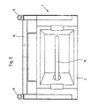
- 2 shows a plan view in the direction of arrow II according to FIG. 1,
- Figure 3
- a front view of the lamp arranged on the support frame,
- Figure 4
- a diagrammatic representation of the beam path of the light at a first setting of the device and
- Figure 5
- a representation of Figure 4 in a second setting of the lighting device.
Wie in den Figuren 1 bis 3 gezeigt umfaßt die Beleuchtungsvorrichtung 1 eine Leuchte 2, einen Umlenkreflektor 3 und eine Reflektionsfläche 4. Der Umlenkreflektor 3 ist am Verbindungsbereich 5 an der Leuchte 2 befestigt. Die Reflektionsfläche 4 ist ihrerseits am Umlenkreflektor 3 befestigt und über eine Verstellmimik 6 verstellbar. Die Reflektionsfläche 4 besteht aus einzelnen Reflektionslamellen 7, welche ihrerseits relativ zueinander verstellbar sind.As shown in FIGS. 1 to 3, the
Im Strahlenausgangsbereich ist an dem Umlenkreflektor eine Abblendklappe 8 angeordnet, die einseitig drehbar gelagert über eine Verstellmimik 9 relativ zum Strahlenweg verstellt werden kann. Die aus Leuchte 2, Umlenkreflektor 3, Reflektionsfläche 4 und Abblendklappe 8 bestehende Baugruppe ist an einem Traggerüst 10 angeordnet. Dabei handelt es sich um ein Leichtbau-Traggerüst, an welchem die Baugruppe mittels Haltelaschen befestigt ist. An dem Traggerüst 10 sind Augenschrauben 11 zur Befestigung der Beleuchtungsvorrichtung 1 im Überwachungsbereich angeordnet. An dem Traggerüst 10 ist ein Ansatzprofil 12 angesetzt, an welchem der Schaltschrank 13 mit einer Bedientafel 14 befestigt ist. Die so entstandene Gesamteinheit ist hinsichtlich des Einsatzortes höchst variabel und hinsichtlich der Einzelelemente wirtschaftlich herstell- und einrichtbar. Die Außenabmessungen einer derartigen Vorrichtung liegen beispielsweise bei 1,4 Meter x 0,7 Meter x 0,5 Meter. Die Vorrichtung kann beispielsweise mittels Ketten an einer Decke abgehängt werden, wozu Schnellverbindungselement wie Karabinerhaken oder dergleichen einsetzbar sind. An der Verstellmimik sind einfache von außen leicht zu bedienende Bedienelemente, beispielsweise Kunststoffkugeln, angeordnet, wie in Figur 2 zu sehen. In die Leuchte 2 ist eine Lampe 15 eingesetzt, bei welcher es sich beispielsweise um eine 250 bis 400 Watt-Lampe handeln kann.In the beam exit area, a
Wie sich aus den Figuren 4 und 5 ergibt, kann der Beleuchtungsbereich mit der erfindungsgemäßen Beleuchtungsvorrichtung 1 optimal eingestellt werden. In Figur 4 befindet sich die Reflektionsfläche 4 in ihrer an der Leuchte angeordneten Position so eingestellt, daß nach etwa einem Meter vom Strahlenaustritt aus dem Leuchtengehäuse ein etwa 1,2 Meter langer beleuchteter Überwachungsbereich entsteht. Durch Absenken der Reflektionsfläche läßt sich dieser Überwachungsbereich gemäß Figur 5 in einen anderen Abstand von der Beleuchtungsvorrichtung verlegen. Die in den Figuren 4 und 5 angegebenen Maße sind nur beispielhaft zur Erläuterung des Ausführungsbeispieles gewählt.As can be seen from FIGS. 4 and 5, the lighting area can be optimally adjusted with the
- 11
- BeleuchtungsvorrichtungLighting device
- 22nd
- Leuchtelamp
- 33rd
- UmlenkreflektorDeflection reflector
- 44th
- ReflektionsflächeReflective surface
- 55
- VerbindungsbereichConnection area
- 66
- VerstellmimikAdjustment facial expressions
- 77
- ReflektionslamelleReflection slat
- 88th
- AbblendklappeDimming flap
- 99
- VerstellmimikAdjustment facial expressions
- 1010th
- TraggerüstShoring
- 1111
- AugenschraubeEye bolt
- 1212th
- AnsatzprofilNeck profile
- 1313
- Schaltschrankswitch cabinet
- 1414
- BedientafelControl panel
- 1515
- Lampelamp
Claims (13)
- Illuminating device, in particular for use in visual quality inspections, having at least one light source (2), and at least one deflecting reflector (3) and at least one reflecting surface (4), the light which radiates from the light source (2) onto the deflecting reflectors being deflected onto the reflecting surface, from which it as well as the light radiating from the light source (2) directly onto the reflecting surface (4) is reflected onto the surface to be illuminated, which is situated outside the device, characterized in that the at least one light source (2), the at least one deflecting reflector (3) and the at least one reflecting surface (4) are connected to one another to form an assembly.
- Illuminating device according to Claim 1, characterized in that the light source is a luminaire (2) with an essentially rectangular front surface.
- Illuminating device according to one of Claims 1 or 2, characterized in that the deflecting reflector (3) is fastened to the light source.
- Illuminating device according to one of the preceding claims, characterized in that the reflecting surface (4) is arranged in the deflecting reflector (3).
- Illuminating device according to one of the preceding claims, characterized in that the reflecting surface (4) is a light sail.
- Illuminating device according to Claim 5, characterized in that the light sail comprises individual reflecting vanes (7).
- Illuminating device according to one of the preceding claims, characterized in that the reflecting surface (4) can be adjusted relative to the beam path of the light.
- Illuminating device according to Claim 6, characterized in that the individual reflecting vanes (7) can be adjusted relative to the beam path of the light.
- Illuminating device according to one of the preceding claims, characterized in that a dim-out cap (8) is arranged in the deflecting reflector (3).
- Illuminating device according to Claim 9, characterized in that the dim-out cap (8) is adjustable.
- Illuminating device according to one of the preceding claims, characterized in that the assembly is fastened to a supporting structure (10).
- Illuminating device according to Claim 11, characterized in that the supporting structure is produced from lightweight sections.
- Illuminating device according to one of Claims 11 or 12, characterized in that a switch gear cabinet (13) for the illuminating device is fastened to the supporting structure.
Applications Claiming Priority (2)
| Application Number | Priority Date | Filing Date | Title |
|---|---|---|---|
| DE9319537U DE9319537U1 (en) | 1993-12-18 | 1993-12-18 | Lighting device |
| DE9319537U | 1993-12-18 |
Publications (2)
| Publication Number | Publication Date |
|---|---|
| EP0658721A1 EP0658721A1 (en) | 1995-06-21 |
| EP0658721B1 true EP0658721B1 (en) | 1997-09-24 |
Family
ID=6902236
Family Applications (1)
| Application Number | Title | Priority Date | Filing Date |
|---|---|---|---|
| EP94119788A Expired - Lifetime EP0658721B1 (en) | 1993-12-18 | 1994-12-15 | Lighting device |
Country Status (2)
| Country | Link |
|---|---|
| EP (1) | EP0658721B1 (en) |
| DE (2) | DE9319537U1 (en) |
Cited By (1)
| Publication number | Priority date | Publication date | Assignee | Title |
|---|---|---|---|---|
| EP1475628A2 (en) | 2003-05-06 | 2004-11-10 | VH Lichttechnische Spezialgeräte GmbH | Illumination device |
Families Citing this family (7)
| Publication number | Priority date | Publication date | Assignee | Title |
|---|---|---|---|---|
| DE19613082C2 (en) * | 1996-04-02 | 1999-10-21 | Koenig & Bauer Ag | Method and device for the qualitative assessment of processed material |
| US6012825A (en) * | 1997-09-02 | 2000-01-11 | Lighting Dimensions | Defect highlighting luminaire and inspection area |
| EP0947827A1 (en) * | 1998-04-03 | 1999-10-06 | VH Lichttechnische Spezialgeräte GmbH | Apparatus for inspecting surfaces of bodies lying in different planes |
| DE29920775U1 (en) * | 1999-11-26 | 2000-03-02 | Spectral Gesellschaft für Lichttechnik mbH, 79111 Freiburg | lamp |
| DE10103781A1 (en) * | 2001-01-29 | 2002-08-22 | Zimmermann Gmbh Co Kg Rudolf | Device for illuminating escape routes, has reflector body replaceably mounted in housing with separate holders for groups of white light LEDs with common wiring systems |
| DE102010047539B4 (en) | 2009-10-07 | 2016-07-28 | Wenker Gmbh & Co. Kg | inspection tunnel |
| FR3101947B1 (en) * | 2019-10-15 | 2023-11-24 | Cie Plastic Omnium Se | Device and method for evaluating the quality of a coating |
Family Cites Families (20)
| Publication number | Priority date | Publication date | Assignee | Title |
|---|---|---|---|---|
| US1782629A (en) * | 1929-01-29 | 1930-11-25 | Floyd N Pape | Shield for motor-vehicle headlights |
| AT202652B (en) * | 1957-02-18 | 1959-03-25 | Licentia Gmbh | Wide beam luminaire |
| US3686495A (en) * | 1969-04-24 | 1972-08-22 | Crouse Hinds Co | Tensioner reflector sheet with press forms |
| DE2417605C3 (en) * | 1974-04-10 | 1980-10-16 | Siemens Ag, 1000 Berlin Und 8000 Muenchen | Broad beam street light |
| GB1482743A (en) * | 1974-09-18 | 1977-08-10 | Wallace Knight Ltd | Lamp housing |
| DE2523643C3 (en) * | 1975-05-28 | 1978-09-21 | Hans-Joachim 4010 Hilden Schurig | Reflector with adjustable beam angle |
| DE2533873C3 (en) * | 1975-07-29 | 1979-01-25 | Erwin Sick Gmbh Optik-Elektronik, 7808 Waldkirch | Device for recognizing bottle colors |
| IT1106658B (en) * | 1978-05-24 | 1985-11-18 | Eurodent Di Conti Giacomo E C | ADJUSTABLE LUMINOUS FLOW LAMP |
| DE7931248U1 (en) * | 1979-11-06 | 1980-01-31 | Ernst Rademacher Gmbh, 4005 Meerbusch | HOUSING FOR A LAMP |
| AT379006B (en) * | 1981-01-09 | 1985-11-11 | Austria Email Eht Ag | WIDE-RADIANT LUMINAIRE WITH AN ESSENTIAL ROD-SHAPED LAMP |
| JPS58127910A (en) * | 1982-01-26 | 1983-07-30 | Suraidetsukusu Kk | Seeing-through device on desk |
| DE8316218U1 (en) * | 1983-06-03 | 1984-08-09 | Licentia Patent-Verwaltungs-Gmbh, 6000 Frankfurt | INTERIOR LAMP FOR A HIGH PRESSURE LAMP |
| DE8528706U1 (en) * | 1985-10-09 | 1986-11-06 | Licentia Patent-Verwaltungs-Gmbh, 6000 Frankfurt | Elongated lamp |
| GB2187902A (en) * | 1986-03-13 | 1987-09-16 | Lutron Electronics Co | Lighting control system |
| DE8715104U1 (en) * | 1987-11-13 | 1988-04-14 | S.L.E. GmbH, 7850 Lörrach | Lighting device |
| DE3822303A1 (en) * | 1987-12-10 | 1989-06-22 | Birkle Gebhard | DEVICE FOR OPTICALLY SCANNING THE SURFACE OF AN OBJECT WHOSE SURFACE IS REFLECTABLE OR SCATTERABLE AND METHOD FOR THEREFORE |
| US4872098A (en) * | 1989-03-20 | 1989-10-03 | Lpi Limited Partnership | Variable beam floodlight |
| FR2653530B1 (en) * | 1989-10-19 | 1992-01-17 | Emc2 | DIRECT OR INDIRECT ELECTRICAL LIGHTING DEVICE, ESPECIALLY WALL OR FLOOR LAMP. |
| DE69311583T2 (en) * | 1992-03-16 | 1998-01-08 | Philips Electronics Nv | lamp |
| DE9204375U1 (en) * | 1992-03-31 | 1992-06-04 | Spectral Gesellschaft Fuer Lichttechnik Mbh, 7800 Freiburg | lamp |
-
1993
- 1993-12-18 DE DE9319537U patent/DE9319537U1/en not_active Expired - Lifetime
-
1994
- 1994-12-15 DE DE59404160T patent/DE59404160D1/en not_active Expired - Fee Related
- 1994-12-15 EP EP94119788A patent/EP0658721B1/en not_active Expired - Lifetime
Cited By (1)
| Publication number | Priority date | Publication date | Assignee | Title |
|---|---|---|---|---|
| EP1475628A2 (en) | 2003-05-06 | 2004-11-10 | VH Lichttechnische Spezialgeräte GmbH | Illumination device |
Also Published As
| Publication number | Publication date |
|---|---|
| DE59404160D1 (en) | 1997-10-30 |
| DE9319537U1 (en) | 1994-09-22 |
| EP0658721A1 (en) | 1995-06-21 |
Similar Documents
| Publication | Publication Date | Title |
|---|---|---|
| DE102007010023B4 (en) | vehicle light | |
| EP1033526B1 (en) | Lamp, in particular for motor vehicles | |
| EP0898686B2 (en) | Lighting fitting with a basic unit as support for at least one lamp | |
| DE102009011794B4 (en) | Lighting arrangement with support profile | |
| EP1077344A2 (en) | Lamp | |
| EP0658721B1 (en) | Lighting device | |
| EP0735311A1 (en) | Indoor illumination system | |
| EP0819232B1 (en) | Adapter for open beam miniature reflectors | |
| DE2611434A1 (en) | LIGHTING DEVICE FOR DISPLAY INSTRUMENTS | |
| EP0040853A1 (en) | Signal lamp | |
| DE4414742A1 (en) | Luminaire with at least one ring-shaped illuminant | |
| EP0952390A2 (en) | Line illumination system | |
| EP3832194B1 (en) | Optical system for influencing the light emitted by an extended light source | |
| EP3686480B1 (en) | Light emitting assembly with variable light emission characteristics | |
| DE19721340A1 (en) | Lamp fitting for at least one artificial light source, e.g. fluorescent tube | |
| EP0616168B1 (en) | Lighting device with profile frame | |
| EP3276251A1 (en) | Lamp with variable outside form | |
| CH712778A2 (en) | Arrangement for emitting light. | |
| EP0833101A1 (en) | Reflector arrangement | |
| EP1205744B1 (en) | Device for the inspection of materials with reflected light suitable for cameras | |
| DE3239783A1 (en) | LIGHTING DEVICE | |
| EP1258675B1 (en) | Illumination device with adjustable light cone | |
| DE4440135A1 (en) | Raster element as light deflection and aperture protection device for room and office lights | |
| EP1843082B1 (en) | Downlighter in particular for use in a corridor | |
| DE19938734A1 (en) | Light, especially for vehicle, has light source arranged so that central light source axis is not parallel to main beam direction in which reflector deflects light from source |
Legal Events
| Date | Code | Title | Description |
|---|---|---|---|
| PUAI | Public reference made under article 153(3) epc to a published international application that has entered the european phase |
Free format text: ORIGINAL CODE: 0009012 |
|
| AK | Designated contracting states |
Kind code of ref document: A1 Designated state(s): BE DE FR GB |
|
| 17P | Request for examination filed |
Effective date: 19950913 |
|
| 17Q | First examination report despatched |
Effective date: 19960712 |
|
| GRAG | Despatch of communication of intention to grant |
Free format text: ORIGINAL CODE: EPIDOS AGRA |
|
| GRAH | Despatch of communication of intention to grant a patent |
Free format text: ORIGINAL CODE: EPIDOS IGRA |
|
| GRAH | Despatch of communication of intention to grant a patent |
Free format text: ORIGINAL CODE: EPIDOS IGRA |
|
| GRAA | (expected) grant |
Free format text: ORIGINAL CODE: 0009210 |
|
| AK | Designated contracting states |
Kind code of ref document: B1 Designated state(s): BE DE FR GB |
|
| REF | Corresponds to: |
Ref document number: 59404160 Country of ref document: DE Date of ref document: 19971030 |
|
| GBT | Gb: translation of ep patent filed (gb section 77(6)(a)/1977) |
Effective date: 19971113 |
|
| ET | Fr: translation filed | ||
| PLBE | No opposition filed within time limit |
Free format text: ORIGINAL CODE: 0009261 |
|
| STAA | Information on the status of an ep patent application or granted ep patent |
Free format text: STATUS: NO OPPOSITION FILED WITHIN TIME LIMIT |
|
| 26N | No opposition filed | ||
| REG | Reference to a national code |
Ref country code: GB Ref legal event code: IF02 |
|
| PGFP | Annual fee paid to national office [announced via postgrant information from national office to epo] |
Ref country code: FR Payment date: 20051219 Year of fee payment: 12 |
|
| PGFP | Annual fee paid to national office [announced via postgrant information from national office to epo] |
Ref country code: GB Payment date: 20051222 Year of fee payment: 12 |
|
| PGFP | Annual fee paid to national office [announced via postgrant information from national office to epo] |
Ref country code: BE Payment date: 20060116 Year of fee payment: 12 |
|
| PGFP | Annual fee paid to national office [announced via postgrant information from national office to epo] |
Ref country code: DE Payment date: 20061214 Year of fee payment: 13 |
|
| PG25 | Lapsed in a contracting state [announced via postgrant information from national office to epo] |
Ref country code: BE Free format text: LAPSE BECAUSE OF NON-PAYMENT OF DUE FEES Effective date: 20061231 |
|
| GBPC | Gb: european patent ceased through non-payment of renewal fee |
Effective date: 20061215 |
|
| REG | Reference to a national code |
Ref country code: FR Ref legal event code: ST Effective date: 20070831 |
|
| PG25 | Lapsed in a contracting state [announced via postgrant information from national office to epo] |
Ref country code: GB Free format text: LAPSE BECAUSE OF NON-PAYMENT OF DUE FEES Effective date: 20061215 |
|
| BERE | Be: lapsed |
Owner name: *VH LICHTTECHNISCHE SPEZIALGERATE G.M.B.H. Effective date: 20061231 |
|
| PG25 | Lapsed in a contracting state [announced via postgrant information from national office to epo] |
Ref country code: FR Free format text: LAPSE BECAUSE OF NON-PAYMENT OF DUE FEES Effective date: 20070102 |
|
| PG25 | Lapsed in a contracting state [announced via postgrant information from national office to epo] |
Ref country code: DE Free format text: LAPSE BECAUSE OF NON-PAYMENT OF DUE FEES Effective date: 20080701 |