EP0656259B1 - Flexodruckmaschine angepasst zum Kurzlauf und Verfahren - Google Patents
Flexodruckmaschine angepasst zum Kurzlauf und Verfahren Download PDFInfo
- Publication number
- EP0656259B1 EP0656259B1 EP94118572A EP94118572A EP0656259B1 EP 0656259 B1 EP0656259 B1 EP 0656259B1 EP 94118572 A EP94118572 A EP 94118572A EP 94118572 A EP94118572 A EP 94118572A EP 0656259 B1 EP0656259 B1 EP 0656259B1
- Authority
- EP
- European Patent Office
- Prior art keywords
- mandrel
- deck
- sleeve
- frame
- roll
- Prior art date
- Legal status (The legal status is an assumption and is not a legal conclusion. Google has not performed a legal analysis and makes no representation as to the accuracy of the status listed.)
- Expired - Lifetime
Links
- 238000000034 method Methods 0.000 title claims description 6
- 238000007774 anilox coating Methods 0.000 claims description 15
- 230000000712 assembly Effects 0.000 claims description 4
- 238000000429 assembly Methods 0.000 claims description 4
- 230000008878 coupling Effects 0.000 claims 1
- 238000010168 coupling process Methods 0.000 claims 1
- 238000005859 coupling reaction Methods 0.000 claims 1
- 230000003028 elevating effect Effects 0.000 claims 1
- 239000012530 fluid Substances 0.000 claims 1
- 238000010276 construction Methods 0.000 description 3
- 244000309464 bull Species 0.000 description 1
- 230000003247 decreasing effect Effects 0.000 description 1
- 230000001771 impaired effect Effects 0.000 description 1
Images


Classifications
-
- B—PERFORMING OPERATIONS; TRANSPORTING
- B41—PRINTING; LINING MACHINES; TYPEWRITERS; STAMPS
- B41F—PRINTING MACHINES OR PRESSES
- B41F5/00—Rotary letterpress machines
- B41F5/24—Rotary letterpress machines for flexographic printing
-
- B—PERFORMING OPERATIONS; TRANSPORTING
- B41—PRINTING; LINING MACHINES; TYPEWRITERS; STAMPS
- B41P—INDEXING SCHEME RELATING TO PRINTING, LINING MACHINES, TYPEWRITERS, AND TO STAMPS
- B41P2227/00—Mounting or handling printing plates; Forming printing surfaces in situ
- B41P2227/20—Means enabling or facilitating exchange of tubular printing or impression members, e.g. printing sleeves, blankets
Definitions
- This invention relates to a deck for, and a method of operating a flexographic press, as set out in the pre-characterizing part of claims 1 and 8 below.
- the plate rolls and often the anilox (inking) rolls need to be replaced. This is because the new plates replace those previously mounted on the plate rolls and, in many cases, the ink cell volume on the anilox roll needs to be adjusted for the new print job.
- flexographic presses support the inking roller (anilox roller) and plate roller on bearings which open to release the rolls for job change. Once open, the rolls are lifted out of the press using a chain hoist or custom designed robot.
- the plate roll consists of a sleeve which is locked onto a mandrel.
- the roll is rotatably supported in bearings at each side of the press.
- the mandrel is cantilever supported from one side while the opposing bearing is dropped away from the mandrel.
- This is analogous to unchucking a mandrel in a center winder such as that seen in co-owned patent No. 2,769,600.
- the plate sleeve is then released from the mandrel and slid sideways to remove it from the press.
- the second style is the "cantilever" supported plate roller.
- a press has been developed which only supports the plate and anilox mandrels from one side of the press. This provides natural access for sleeve removal.
- the major problem with this design is that, for presses wider than about 2 / 5 metre (16 inches), the printing performance is impaired due to the limited stiffness provided by a cantilever support. Additionally, the mechanism to allow precise adjustment of the roll positions are complex, sensitive and expensive.
- the invention which is defined in the appended claims avoids the above problems through cantilever mounting a mandrel on which a sleeve is mounted and providing means for raising the mandrel and sleeve to provide advantageous clearance. Further, the sleeve is not fixed to the mandrel but instead rotates on the stationary mandrel (commonly called a dead shaft).
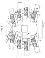
- the numeral 10 designates generally the main frame of the press. Rotatably supported on the main frame is a central impression cylinder 11. Disposed about the central impression cylinder 11 are a plurality of deck frames 12. Each deck frame 12 supports enclosures 13 for deck positioning motors (see FIG. 3 also), an anilox roll or cylinder generally designated 14 and a plate roll or cylinder generally designated 15. This much is conventional and can be seen in greater detail in co-owned patent No. 4,520,728.
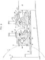
- the deck frame 12 includes a pair of spaced-apart, upwardly facing linear bearing rails 16, 17 -- see also FIG. 3. Slidably mounted on the rail 16 are linear bearing blocks 18, 19 (see FIG. 2) and their opposite counterparts 20, 21 on rail 17 -- see FIG. 3. The blocks 18, 20 carry the plate roll 15 while the blocks 19, 21 carry the anilox roll 14. Also seen in FIG. 2 is a ball screw means 22 which extends into the enclosures 13 and is used to position the rolls 14, 15 relative to each other and to the impression cylinder 11.
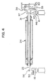
- the anilox roll will be described -- and in conjunction with FIG. 4.
- the numeral 23 designates an axially disposed, non-rotating mandrel, i.e., dead shaft or mandrel.
- a sleeve assembly generally designated 24.
- the elements of sleeve assembly 24 can be more readily appreciated from FIG. 5 where the sleeve assembly 24 is partially removed from the mandrel 23.
- the sleeve assembly includes an outer sleeve 25, end plates 26, 27 and an inner sleeve 28 -- this also being spaced radially from the mandrel 23, see especially the left hand end of FIG. 5 at 28.
- the sleeve assembly thus includes elements 25-28 and further roller bearings 29, 30 at the ends thereof. These are fixed to the sleeve assembly 24 and rotate on the mandrel 23.
- the numeral 31 designates a positioning hub located adjacent the bearing 29.
- the sleeve assembly 24 carries gearing 32 -- adjacent the bearing 30.
- the only element carried by the mandrel 23 is a stop 33 -- see the right hand end of FIG. 5.
- the mandrel 23 is fixed to a bracket 37 -- see the upper right hand portion of either FIG. 4 or FIG. 5.
- the bracket 37 in turn is slidably mounted on a vertically extending guide 38.
- the guide 38 is rigidly mounted on a subframe 39 carried by the block 21.
- the subframe 39 rigidly supports an air cylinder 40.
- the air cylinder 40 has a piston rod 41 which is connected to the bracket 37 by a horizontal arm 42 -- see also the right hand upper portion of FIG. 2.
- the mandrel 23 has been raised somewhat by the cylinder 40 but raised even further in FIG. 5 so as to clear the saddle 43 carried by the block 19 -- see the left hand portion of FIG. 5.
- a corresponding saddle is provided at the right hand end at 45. This is carried by the block 21 as is the holder 46 for positioning hub 31.
- the blocks 18-21 are carried on the rails 16, 17 which in turn are fixed to the deck frame 12 -- more especially the deck wings 12a, 12b as seen in FIG. 5. Also seen in FIG. 5 are two ball screws in each block 19, 21 so as to individually position the two rolls 14, 15. Further seen in FIG. 5 is a Sunday-drive gear 47 which permits the anilox roll to be turned over slowly to keep ink from setting therein -- as when the plate roll is being changed or other press stoppage occurs.
- both rolls 14, 15 are essentially the same -- having sleeve assemblies rotatably mounted on a dead shaft or stationary mandrel and with the mandrel liftable in cantilever fashion so as to permit unsleeving of the sleeve assembly therefrom.
- gears are located inside of deck frame 12a which is different from conventional practice and allows the gearing 48 to be changed with the sleeve assembly 51 on the plate roll 15.
- side register is developed by means provided inside the deck frame 12 -- this by the hub 52 and holder 53 which are inboard of the deck wing 12b -- and which corresponds generally to the hub 31 and holder 46 described in conjunction with the anilox roll.
Landscapes
- Engineering & Computer Science (AREA)
- Mechanical Engineering (AREA)
- Rotary Presses (AREA)
- Inking, Control Or Cleaning Of Printing Machines (AREA)
- Rolls And Other Rotary Bodies (AREA)
Claims (10)
- Druckwerk für eine Flexodruckmaschine mit einem Druckwerkrahmen (12), der in der Maschine (10) relativ zu einem zentralen Druckzylinder (11) bewegbar anordenbar ist, sowie einer Plattenrolle (15) und einer Aniloxrolle (14), die jeweils drehbar auf dem Druckwerkrahmen drehbar angeordnet sind, dadurch gekennzeichnet,
daß die beiden Rollen jeweils einen axial verlaufenden feststehenden Dorn (23, 58) und eine Hülsenanordnung (24, 51) aufweisen, die konzentrisch mit dem Dorn und auf diesem drehbar angeordnet ist, daß eine Zahnteilung (32, 34) auf den Hülsenanordnung angeordnet ist, um diese zu drehen, daß eine Auflagereinrichtung (43, 45) auf dem Rahmen jeden Dorn an jedem Dornende haltert und daß eine Hebeeinrichtung (37 - 40) auf dem Rahmen an einem der Ende jedes Dorns angeordnet ist, um jeden Dorn frei auskragend anzuheben und dabei sein anderes Ende vom Auflager (43) freizuheben, wodurch die zugehörige Hülsenanordnung sich zum Wechsel abnehmen läßt. - Druckwerk nach Anspruch 1, bei dem die Auflagereinrichtung (43) am anderen Ende mit einer Verschlußeinrichtung (54 - 60) versehen ist.
- Druckwerk nach Anspruch 1, bei dem jede Hülsenanordnung mit einer Stellnabeneinrichtung (31, 52) versehen ist und der Rahmen einen Nabenhalter (46, 53) aufweist, der die Nabeneinrichtung abnehmbar aufnimmt.
- Druckwerk nach Anspruch 1, bei dem die Hebeeinrichtung einen Druckmittelzylinder und eine Kolbenrolleneinheit (40, 61) aufweist, die eine an ihr festliegende Winkeleinrichtung (37) trägt, wobei der Dorn starr mit der Winkeleinrichtung gekoppelt ist.
- Druckwerk nach Anspruch 1, bei dem das Gestell ein Paar seitlicher Flügel (12a, 12b) aufweist, wobei auf jedem der seitlichen Flügel ein Auflager (43, 45) angeordnet ist und das Auflager (43) auf dem anderen seitlichen Flügel (12a) mit einer Verschlußeinrichtung (54, 55) versehen ist, die mit der Hebeeinrichtung zusammenwirkend den Dorn bei arbeitender Druckmaschine in der Solllage hält.
- Druckwerk nach Anspruch 1, bei dem die Hülsenanordnungen jeweils eine Innen- und eine Außenhülse (28 bzw. 25) sowie Endplatten (26, 27) aufweisen, die die Innen- mit der Außenhülse verbinden.
- Druckwerk nach Anspruch 6, bei dem die Innenhülse außerhab der Endplatten Lagereinrichtungen (29, 30) aufweist, die den Dorn aufnehmen.
- Verfahren zum Betreiben einer Flexodruckmaschine, bei dem man ein Maschinengestell mit einer Vielzahl von Druckwerkrahmen (12) vorsieht, die jeweils eine Plattenrolle (15) und eine Aniloxrolle (14) abnehmbar tragen, wobei jede Rolle eine Hülsenanordnung (24, 51) aufweist, die auf einem feststehenden Dorn (23) drehbar gelagert und an ihren Enden abgestützt ist, dadurch gekennzeichnet, daß manauf jedem Druckwerkrahmen an einem Ende jedes Dorns eine Hebeeinrichtung (37 - 40) vorsieht, mit der der Dorn jeweils frei auskragend an- und dabei sein anderes Ende vom Auflager abhebbar ist,eine der Rollen anhebt (61, 40), um sie an einem Ende vom Auflager freizuheben, unddie ersterwähnte durch eine andere Hülse ersetzt.
- Verfahren nach Anspruch 8, bei dem man einen Druckwerkrahmen sowie auf der Hülse einwärts des Rahmens Zahnteilungen vorsieht.
- Verfahren nach Anspruch 8, bei dem man die Hülsen beider Rollen auswechselt.
Applications Claiming Priority (2)
| Application Number | Priority Date | Filing Date | Title |
|---|---|---|---|
| US160575 | 1993-12-01 | ||
| US08/160,575 US5370047A (en) | 1993-12-01 | 1993-12-01 | Flexographic press adapted for short runs and method |
Publications (2)
| Publication Number | Publication Date |
|---|---|
| EP0656259A1 EP0656259A1 (de) | 1995-06-07 |
| EP0656259B1 true EP0656259B1 (de) | 1998-05-13 |
Family
ID=22577458
Family Applications (1)
| Application Number | Title | Priority Date | Filing Date |
|---|---|---|---|
| EP94118572A Expired - Lifetime EP0656259B1 (de) | 1993-12-01 | 1994-11-25 | Flexodruckmaschine angepasst zum Kurzlauf und Verfahren |
Country Status (6)
| Country | Link |
|---|---|
| US (1) | US5370047A (de) |
| EP (1) | EP0656259B1 (de) |
| JP (1) | JP3402808B2 (de) |
| CA (1) | CA2134298A1 (de) |
| DE (1) | DE69410218T2 (de) |
| ES (1) | ES2115136T3 (de) |
Families Citing this family (37)
| Publication number | Priority date | Publication date | Assignee | Title |
|---|---|---|---|---|
| US5584246A (en) * | 1995-06-09 | 1996-12-17 | Werner Kammann Maschinenfabrik Gmbh | Process and apparatus for printing on flat individual articles |
| ATE176194T1 (de) * | 1995-10-18 | 1999-02-15 | Fischer & Krecke Gmbh & Co | Vorrichtung zum wechseln von druckzylinderhülsen in druckmaschinen |
| US5778779A (en) * | 1996-01-04 | 1998-07-14 | Heidelberger Druckmaschinen Ag | Printing unit and register mechanism for mounting a printing sleeve |
| EP0881071A3 (de) * | 1996-06-12 | 1998-12-09 | Fischer & Krecke Gmbh & Co. | Druckmaschine |
| US6113346A (en) | 1996-07-31 | 2000-09-05 | Agfa Corporation | Method for loading and unloading a supply of plates in an automated plate handler |
| US5816154A (en) * | 1997-05-09 | 1998-10-06 | Bryce International, L.L.C. | Print cylinder support for axial removal of a cylindrical sleeve |
| IT1299666B1 (it) | 1998-05-05 | 2000-03-24 | Uteco Spa Roto Flexo & Convert | Macchina rotativa flessografica a tamburo centrale a piu' colori |
| US6176184B1 (en) | 1999-04-16 | 2001-01-23 | Paper Converting Machine Company | Dryer for flexographic and gravure printing |
| US6142073A (en) * | 1999-08-20 | 2000-11-07 | Paper Converting Maching Company | Method and apparatus for exchanging a roll of a printing press |
| US6176181B1 (en) | 1999-08-20 | 2001-01-23 | Paper Converting Machine Company | Deck configuration for a printing press |
| EP1090754B1 (de) * | 1999-10-06 | 2003-08-06 | Fischer & Krecke Gmbh & Co. | Vorrichtung zum Wechseln einer Druckzylinderhülse |
| DE50000183D1 (de) | 2000-02-10 | 2002-07-04 | Fischer & Krecke Gmbh & Co | Rasterwalze für Flexodruckmaschine |
| EP1221367B2 (de) * | 2001-01-04 | 2010-09-08 | Fischer & Krecke Gmbh & Co. | Verfahren zum Wechseln einer Druckzylinderhülse und Druckmaschine zur Durchführung des Verfahrens |
| DE10103632B4 (de) * | 2001-01-27 | 2013-08-22 | Manroland Web Systems Gmbh | Rollenrotationsdruckmaschine |
| US6892639B2 (en) | 2001-04-05 | 2005-05-17 | Paper Converting Machine Co. | Flexographic printing press with integrated dryer |
| EP1377453B2 (de) | 2001-04-09 | 2009-09-16 | Koenig & Bauer Aktiengesellschaft | Druckwerk einer druckmaschine |
| CN100446974C (zh) | 2001-04-09 | 2008-12-31 | 柯尼格及包尔公开股份有限公司 | 印刷机的印刷装置 |
| US6684783B2 (en) | 2001-08-17 | 2004-02-03 | Creo Inc. | Method for imaging a media sleeve on a computer-to-plate imaging machine |
| US7809253B2 (en) * | 2001-08-27 | 2010-10-05 | Flexair, Inc. | Compact air drying system |
| US7187856B2 (en) * | 2001-08-27 | 2007-03-06 | Flexair, Inc. | Compact integrated forced air drying system |
| US6931205B2 (en) * | 2001-08-27 | 2005-08-16 | Flexair, Inc. | Compact integrated forced air drying system |
| DE10220608C1 (de) * | 2002-05-08 | 2003-11-06 | Windmoeller & Hoelscher | Druckmaschine |
| US6840166B2 (en) * | 2002-06-12 | 2005-01-11 | Machine Engineering, Inc. | Mandrel trip apparatus |
| ES2242520B1 (es) * | 2004-01-14 | 2007-02-16 | Comexi, S.A. | Dispositivo automatico de manipulacion y transporte de camisas de impresion. |
| US20090069926A1 (en) * | 2007-09-11 | 2009-03-12 | Awea Mechantronic Co., Ltd. | CNC apparatus with mechanism for controlling length variation of lead screw due to thermal expansion and method therefor |
| ES2319952B1 (es) * | 2008-09-29 | 2010-07-13 | Neopack, S.L. | Maquina impresora y grupo impresor para offset de formato variable. |
| US20100122638A1 (en) * | 2008-11-18 | 2010-05-20 | C.G. Bretting Manufacturing Co., Inc. | Flexographic Printing Apparatus And Method |
| KR101203895B1 (ko) | 2010-05-04 | 2012-11-23 | 주식회사 에스에프에이 | 패턴 인쇄장치 |
| US9199446B2 (en) * | 2010-06-25 | 2015-12-01 | Global Web Finishing, Llc | Coating apparatus and method |
| IT1401510B1 (it) * | 2010-08-03 | 2013-07-26 | Nuova Gidue S R L | Gruppo di stampa perfezionato, particolarmente per stampe flessografiche con cilindro di stampa rimovibile. |
| ES2403133T3 (es) | 2010-11-05 | 2013-05-14 | Neopack, S.L. | Máquina impresora offset de formato variable dotada de un cilindro central de impresión |
| GB201200758D0 (en) * | 2012-01-17 | 2012-02-29 | H L North East Holdings Ltd | Flexographic printing apparatus and process |
| US8707866B2 (en) | 2012-03-21 | 2014-04-29 | James M. Jeter | Rail guide mounting assembly for mandrel trip apparatus |
| CN105807500B (zh) * | 2016-05-31 | 2019-03-12 | 京东方科技集团股份有限公司 | 转印装置和转印方法 |
| US11390067B2 (en) * | 2017-04-07 | 2022-07-19 | Bobst Firenze S.R.L. | Printing unit with interchangeable printing sleeve |
| CN108705851A (zh) * | 2018-05-16 | 2018-10-26 | 滁州市大茆皮革机械有限公司 | 一种合成革生产用印刷机 |
| CN109926809B (zh) * | 2019-04-22 | 2021-03-05 | 陕西北人印刷机械有限责任公司 | 一种夹具 |
Family Cites Families (11)
| Publication number | Priority date | Publication date | Assignee | Title |
|---|---|---|---|---|
| GB1581233A (en) * | 1976-06-02 | 1980-12-10 | Drg Uk Ltd | Printing press |
| FR2485990A1 (fr) * | 1980-07-03 | 1982-01-08 | Holweg Const Mec | Dispositif pour le changement automatique de cylindres d'une imprimeuse flexographique |
| US4386566A (en) * | 1980-10-06 | 1983-06-07 | Mosstype Corporation | Mandrel assembly for demountable printing cylinder |
| DE3401626A1 (de) * | 1984-01-18 | 1985-07-18 | Fischer & Krecke, 4800 Bielefeld | Flexodruckmaschine mit temperaturstabilisiertem druckmaschinengestell |
| DE3500319A1 (de) * | 1984-12-04 | 1986-06-05 | Windmöller & Hölscher, 4540 Lengerich | Lagerung fuer formatzylinder einer druckmaschine, vorzugsweise flexodruckmaschine, mit austauschbaren huelsenfoermigen formatzylindermaenteln |
| DE3543704A1 (de) * | 1985-12-11 | 1987-06-19 | Md Papierfabrik Pasing Nicolau | Vorrichtung und verfahren zum bedrucken einer bahn |
| GB8611722D0 (en) * | 1986-05-14 | 1986-06-25 | Drg Uk Ltd | Processing paper & other webs |
| IT1234647B (it) * | 1989-06-02 | 1992-05-26 | Uteco Flexo & Converting Machi | Macchina flexografica a piu' colori con dispositivo per il carico e lo scarico automatico dei cilindri portacliche' |
| DE4008501A1 (de) * | 1989-12-18 | 1991-06-20 | Windmoeller & Hoelscher | Druckmaschine mit presseurs mit austauschbaren huelsenfoermigen presseurmaenteln |
| US5140899A (en) * | 1991-08-30 | 1992-08-25 | Allied Gear & Machine Company | Anilox roll mounting means |
| US5289769A (en) * | 1992-08-17 | 1994-03-01 | W. O. Hickok Mfg., Co. | Method and apparatus for changing a printing sleeve |
-
1993
- 1993-12-01 US US08/160,575 patent/US5370047A/en not_active Expired - Fee Related
-
1994
- 1994-10-25 CA CA002134298A patent/CA2134298A1/en not_active Abandoned
- 1994-11-16 JP JP30681294A patent/JP3402808B2/ja not_active Expired - Fee Related
- 1994-11-25 ES ES94118572T patent/ES2115136T3/es not_active Expired - Lifetime
- 1994-11-25 EP EP94118572A patent/EP0656259B1/de not_active Expired - Lifetime
- 1994-11-25 DE DE69410218T patent/DE69410218T2/de not_active Expired - Fee Related
Also Published As
| Publication number | Publication date |
|---|---|
| DE69410218T2 (de) | 1998-09-03 |
| ES2115136T3 (es) | 1998-06-16 |
| US5370047A (en) | 1994-12-06 |
| DE69410218D1 (de) | 1998-06-18 |
| JP3402808B2 (ja) | 2003-05-06 |
| EP0656259A1 (de) | 1995-06-07 |
| JPH07195655A (ja) | 1995-08-01 |
| CA2134298A1 (en) | 1995-06-02 |
Similar Documents
| Publication | Publication Date | Title |
|---|---|---|
| EP0656259B1 (de) | Flexodruckmaschine angepasst zum Kurzlauf und Verfahren | |
| US3783780A (en) | Intaglio print machine with novel roll mounting mandrel and bushing assembly | |
| US4697516A (en) | Mounting means for plate cylinders of a printing machine having replaceable sleevelike plate cylinder shells | |
| US5188027A (en) | Printing apparatus with quickly changeable printing plate | |
| EP0955161B2 (de) | Flexographische Mehrfarben-Rotationsdruckmaschine mit einer Haupttrommel und getrennten, unabhängigen Farbdruckeinheiten | |
| JP3863953B2 (ja) | カウンターポイズ及びリフト装置 | |
| EP0956951B1 (de) | Einrichtung zur Verstellung von Druckwerkzylindern in Druckwerken von Rotationsdruckmaschine | |
| EP2407307B1 (de) | Druckeinheit und Druckverfahren mit variabler Drucklänge | |
| JPH0671845A (ja) | 異なるカットオフ寸法の印刷シリンダを有する多目的印刷機システム | |
| JP4406097B2 (ja) | 印刷機 | |
| RU2127196C1 (ru) | Печатающее устройство для ротационной печатной машины | |
| US20030019374A1 (en) | Flexographic printing machine | |
| EP0737569B1 (de) | Druckmaschine mit Vorrichtung zum schnellen Wechseln der Zylinderendhülsen des Farbwerkes | |
| EP1285753B1 (de) | Druckvorrichtung, insbesondere flexographische Druckmaschine | |
| US11279123B2 (en) | Application unit with positioning device | |
| JP2007176177A (ja) | ウェブ係合が改良された印刷機、及び対応するウェブ係合方法 | |
| JP3418944B2 (ja) | グラビア印刷機の版胴交換装置 | |
| EP0040183B1 (de) | Druckwerk innerhalb eines Bogenoffsetrotationsdruckmaschine | |
| WO2010059707A2 (en) | Flexographic printing apparatus and method | |
| CN1110412C (zh) | 用于照相凹版印刷机的印刷组件 | |
| EP0311217B1 (de) | Mehrfarbenrotationssiebdruckmaschine | |
| US4856429A (en) | Flexographic printing machine, especially for flexographic blank printing | |
| EP1863640B1 (de) | Hebemechanismus für einen freitragenden gummizylinder | |
| JP2626786B2 (ja) | グラビア輪転機の版胴交換着脱方法および装置 | |
| US11390068B2 (en) | Application unit with positioning device and magazine |
Legal Events
| Date | Code | Title | Description |
|---|---|---|---|
| PUAI | Public reference made under article 153(3) epc to a published international application that has entered the european phase |
Free format text: ORIGINAL CODE: 0009012 |
|
| AK | Designated contracting states |
Kind code of ref document: A1 Designated state(s): DE ES FR GB IT SE |
|
| 17P | Request for examination filed |
Effective date: 19951012 |
|
| 17Q | First examination report despatched |
Effective date: 19961126 |
|
| GRAG | Despatch of communication of intention to grant |
Free format text: ORIGINAL CODE: EPIDOS AGRA |
|
| GRAG | Despatch of communication of intention to grant |
Free format text: ORIGINAL CODE: EPIDOS AGRA |
|
| GRAH | Despatch of communication of intention to grant a patent |
Free format text: ORIGINAL CODE: EPIDOS IGRA |
|
| GRAH | Despatch of communication of intention to grant a patent |
Free format text: ORIGINAL CODE: EPIDOS IGRA |
|
| GRAA | (expected) grant |
Free format text: ORIGINAL CODE: 0009210 |
|
| AK | Designated contracting states |
Kind code of ref document: B1 Designated state(s): DE ES FR GB IT SE |
|
| REG | Reference to a national code |
Ref country code: ES Ref legal event code: FG2A Ref document number: 2115136 Country of ref document: ES Kind code of ref document: T3 |
|
| REF | Corresponds to: |
Ref document number: 69410218 Country of ref document: DE Date of ref document: 19980618 |
|
| ITF | It: translation for a ep patent filed | ||
| ET | Fr: translation filed | ||
| PLBE | No opposition filed within time limit |
Free format text: ORIGINAL CODE: 0009261 |
|
| STAA | Information on the status of an ep patent application or granted ep patent |
Free format text: STATUS: NO OPPOSITION FILED WITHIN TIME LIMIT |
|
| 26N | No opposition filed | ||
| PGFP | Annual fee paid to national office [announced via postgrant information from national office to epo] |
Ref country code: FR Payment date: 19991020 Year of fee payment: 6 |
|
| PGFP | Annual fee paid to national office [announced via postgrant information from national office to epo] |
Ref country code: SE Payment date: 19991022 Year of fee payment: 6 |
|
| PGFP | Annual fee paid to national office [announced via postgrant information from national office to epo] |
Ref country code: GB Payment date: 19991025 Year of fee payment: 6 |
|
| PG25 | Lapsed in a contracting state [announced via postgrant information from national office to epo] |
Ref country code: GB Free format text: LAPSE BECAUSE OF NON-PAYMENT OF DUE FEES Effective date: 20001125 |
|
| PG25 | Lapsed in a contracting state [announced via postgrant information from national office to epo] |
Ref country code: SE Free format text: THE PATENT HAS BEEN ANNULLED BY A DECISION OF A NATIONAL AUTHORITY Effective date: 20001129 |
|
| EUG | Se: european patent has lapsed |
Ref document number: 94118572.0 |
|
| GBPC | Gb: european patent ceased through non-payment of renewal fee |
Effective date: 20001125 |
|
| PG25 | Lapsed in a contracting state [announced via postgrant information from national office to epo] |
Ref country code: FR Free format text: LAPSE BECAUSE OF NON-PAYMENT OF DUE FEES Effective date: 20010731 |
|
| REG | Reference to a national code |
Ref country code: FR Ref legal event code: ST |
|
| PGFP | Annual fee paid to national office [announced via postgrant information from national office to epo] |
Ref country code: DE Payment date: 20041022 Year of fee payment: 11 |
|
| PGFP | Annual fee paid to national office [announced via postgrant information from national office to epo] |
Ref country code: ES Payment date: 20041129 Year of fee payment: 11 |
|
| PG25 | Lapsed in a contracting state [announced via postgrant information from national office to epo] |
Ref country code: IT Free format text: LAPSE BECAUSE OF NON-PAYMENT OF DUE FEES Effective date: 20051125 |
|
| PG25 | Lapsed in a contracting state [announced via postgrant information from national office to epo] |
Ref country code: ES Free format text: LAPSE BECAUSE OF NON-PAYMENT OF DUE FEES Effective date: 20051126 |
|
| PG25 | Lapsed in a contracting state [announced via postgrant information from national office to epo] |
Ref country code: DE Free format text: LAPSE BECAUSE OF NON-PAYMENT OF DUE FEES Effective date: 20060601 |
|
| REG | Reference to a national code |
Ref country code: ES Ref legal event code: FD2A Effective date: 20051126 |