EP0655772A2 - Method and apparatus for scrubbing substrate - Google Patents
Method and apparatus for scrubbing substrate Download PDFInfo
- Publication number
- EP0655772A2 EP0655772A2 EP94307442A EP94307442A EP0655772A2 EP 0655772 A2 EP0655772 A2 EP 0655772A2 EP 94307442 A EP94307442 A EP 94307442A EP 94307442 A EP94307442 A EP 94307442A EP 0655772 A2 EP0655772 A2 EP 0655772A2
- Authority
- EP
- European Patent Office
- Prior art keywords
- substrate
- scrubbing
- chuck
- face
- back pressure
- Prior art date
- Legal status (The legal status is an assumption and is not a legal conclusion. Google has not performed a legal analysis and makes no representation as to the accuracy of the status listed.)
- Withdrawn
Links
- 239000000758 substrate Substances 0.000 title claims abstract description 380
- 238000005201 scrubbing Methods 0.000 title claims abstract description 114
- 238000000034 method Methods 0.000 title claims abstract description 18
- 239000012530 fluid Substances 0.000 claims abstract description 56
- 230000007246 mechanism Effects 0.000 claims description 21
- 230000002093 peripheral effect Effects 0.000 claims description 7
- 238000001035 drying Methods 0.000 claims description 4
- 239000004065 semiconductor Substances 0.000 description 19
- 239000000428 dust Substances 0.000 description 12
- 239000002245 particle Substances 0.000 description 11
- 239000007788 liquid Substances 0.000 description 10
- 238000004519 manufacturing process Methods 0.000 description 10
- 238000006073 displacement reaction Methods 0.000 description 8
- 239000012498 ultrapure water Substances 0.000 description 7
- 239000007789 gas Substances 0.000 description 6
- QSHDDOUJBYECFT-UHFFFAOYSA-N mercury Chemical compound [Hg] QSHDDOUJBYECFT-UHFFFAOYSA-N 0.000 description 6
- 229910052753 mercury Inorganic materials 0.000 description 6
- 239000003570 air Substances 0.000 description 5
- 230000009467 reduction Effects 0.000 description 5
- IJGRMHOSHXDMSA-UHFFFAOYSA-N Atomic nitrogen Chemical compound N#N IJGRMHOSHXDMSA-UHFFFAOYSA-N 0.000 description 4
- 239000012080 ambient air Substances 0.000 description 3
- 238000004140 cleaning Methods 0.000 description 3
- 230000010354 integration Effects 0.000 description 3
- XLYOFNOQVPJJNP-UHFFFAOYSA-N water Substances O XLYOFNOQVPJJNP-UHFFFAOYSA-N 0.000 description 3
- XKRFYHLGVUSROY-UHFFFAOYSA-N Argon Chemical compound [Ar] XKRFYHLGVUSROY-UHFFFAOYSA-N 0.000 description 2
- CURLTUGMZLYLDI-UHFFFAOYSA-N Carbon dioxide Chemical compound O=C=O CURLTUGMZLYLDI-UHFFFAOYSA-N 0.000 description 2
- 238000011109 contamination Methods 0.000 description 2
- 238000010586 diagram Methods 0.000 description 2
- 229910001873 dinitrogen Inorganic materials 0.000 description 2
- 238000010981 drying operation Methods 0.000 description 2
- 239000011521 glass Substances 0.000 description 2
- 239000011261 inert gas Substances 0.000 description 2
- 230000004048 modification Effects 0.000 description 2
- 238000012986 modification Methods 0.000 description 2
- 230000032258 transport Effects 0.000 description 2
- YZCKVEUIGOORGS-OUBTZVSYSA-N Deuterium Chemical compound [2H] YZCKVEUIGOORGS-OUBTZVSYSA-N 0.000 description 1
- 230000009471 action Effects 0.000 description 1
- 150000001298 alcohols Chemical class 0.000 description 1
- XAGFODPZIPBFFR-UHFFFAOYSA-N aluminium Chemical compound [Al] XAGFODPZIPBFFR-UHFFFAOYSA-N 0.000 description 1
- 229910052782 aluminium Inorganic materials 0.000 description 1
- PNEYBMLMFCGWSK-UHFFFAOYSA-N aluminium oxide Inorganic materials [O-2].[O-2].[O-2].[Al+3].[Al+3] PNEYBMLMFCGWSK-UHFFFAOYSA-N 0.000 description 1
- 229910052786 argon Inorganic materials 0.000 description 1
- 230000004888 barrier function Effects 0.000 description 1
- 238000005452 bending Methods 0.000 description 1
- 229910002092 carbon dioxide Inorganic materials 0.000 description 1
- 239000001569 carbon dioxide Substances 0.000 description 1
- 239000000919 ceramic Substances 0.000 description 1
- 239000013078 crystal Substances 0.000 description 1
- 230000002950 deficient Effects 0.000 description 1
- 229910052805 deuterium Inorganic materials 0.000 description 1
- 230000005611 electricity Effects 0.000 description 1
- 238000010894 electron beam technology Methods 0.000 description 1
- 230000006872 improvement Effects 0.000 description 1
- 230000001678 irradiating effect Effects 0.000 description 1
- 238000002955 isolation Methods 0.000 description 1
- 229910052757 nitrogen Inorganic materials 0.000 description 1
- 238000003825 pressing Methods 0.000 description 1
- 230000002265 prevention Effects 0.000 description 1
- 230000004224 protection Effects 0.000 description 1
- 230000008844 regulatory mechanism Effects 0.000 description 1
- 229910052594 sapphire Inorganic materials 0.000 description 1
- 239000010980 sapphire Substances 0.000 description 1
- 230000003068 static effect Effects 0.000 description 1
Images


Classifications
-
- H—ELECTRICITY
- H01—ELECTRIC ELEMENTS
- H01L—SEMICONDUCTOR DEVICES NOT COVERED BY CLASS H10
- H01L21/00—Processes or apparatus adapted for the manufacture or treatment of semiconductor or solid state devices or of parts thereof
- H01L21/67—Apparatus specially adapted for handling semiconductor or electric solid state devices during manufacture or treatment thereof; Apparatus specially adapted for handling wafers during manufacture or treatment of semiconductor or electric solid state devices or components ; Apparatus not specifically provided for elsewhere
- H01L21/683—Apparatus specially adapted for handling semiconductor or electric solid state devices during manufacture or treatment thereof; Apparatus specially adapted for handling wafers during manufacture or treatment of semiconductor or electric solid state devices or components ; Apparatus not specifically provided for elsewhere for supporting or gripping
- H01L21/687—Apparatus specially adapted for handling semiconductor or electric solid state devices during manufacture or treatment thereof; Apparatus specially adapted for handling wafers during manufacture or treatment of semiconductor or electric solid state devices or components ; Apparatus not specifically provided for elsewhere for supporting or gripping using mechanical means, e.g. chucks, clamps or pinches
- H01L21/68714—Apparatus specially adapted for handling semiconductor or electric solid state devices during manufacture or treatment thereof; Apparatus specially adapted for handling wafers during manufacture or treatment of semiconductor or electric solid state devices or components ; Apparatus not specifically provided for elsewhere for supporting or gripping using mechanical means, e.g. chucks, clamps or pinches the wafers being placed on a susceptor, stage or support
- H01L21/68728—Apparatus specially adapted for handling semiconductor or electric solid state devices during manufacture or treatment thereof; Apparatus specially adapted for handling wafers during manufacture or treatment of semiconductor or electric solid state devices or components ; Apparatus not specifically provided for elsewhere for supporting or gripping using mechanical means, e.g. chucks, clamps or pinches the wafers being placed on a susceptor, stage or support characterised by a plurality of separate clamping members, e.g. clamping fingers
-
- B—PERFORMING OPERATIONS; TRANSPORTING
- B08—CLEANING
- B08B—CLEANING IN GENERAL; PREVENTION OF FOULING IN GENERAL
- B08B1/00—Cleaning by methods involving the use of tools
- B08B1/30—Cleaning by methods involving the use of tools by movement of cleaning members over a surface
- B08B1/32—Cleaning by methods involving the use of tools by movement of cleaning members over a surface using rotary cleaning members
-
- B—PERFORMING OPERATIONS; TRANSPORTING
- B08—CLEANING
- B08B—CLEANING IN GENERAL; PREVENTION OF FOULING IN GENERAL
- B08B11/00—Cleaning flexible or delicate articles by methods or apparatus specially adapted thereto
- B08B11/02—Devices for holding articles during cleaning
-
- B—PERFORMING OPERATIONS; TRANSPORTING
- B24—GRINDING; POLISHING
- B24B—MACHINES, DEVICES, OR PROCESSES FOR GRINDING OR POLISHING; DRESSING OR CONDITIONING OF ABRADING SURFACES; FEEDING OF GRINDING, POLISHING, OR LAPPING AGENTS
- B24B29/00—Machines or devices for polishing surfaces on work by means of tools made of soft or flexible material with or without the application of solid or liquid polishing agents
- B24B29/02—Machines or devices for polishing surfaces on work by means of tools made of soft or flexible material with or without the application of solid or liquid polishing agents designed for particular workpieces
-
- B—PERFORMING OPERATIONS; TRANSPORTING
- B24—GRINDING; POLISHING
- B24B—MACHINES, DEVICES, OR PROCESSES FOR GRINDING OR POLISHING; DRESSING OR CONDITIONING OF ABRADING SURFACES; FEEDING OF GRINDING, POLISHING, OR LAPPING AGENTS
- B24B37/00—Lapping machines or devices; Accessories
- B24B37/04—Lapping machines or devices; Accessories designed for working plane surfaces
-
- B—PERFORMING OPERATIONS; TRANSPORTING
- B24—GRINDING; POLISHING
- B24B—MACHINES, DEVICES, OR PROCESSES FOR GRINDING OR POLISHING; DRESSING OR CONDITIONING OF ABRADING SURFACES; FEEDING OF GRINDING, POLISHING, OR LAPPING AGENTS
- B24B37/00—Lapping machines or devices; Accessories
- B24B37/27—Work carriers
- B24B37/30—Work carriers for single side lapping of plane surfaces
-
- B—PERFORMING OPERATIONS; TRANSPORTING
- B24—GRINDING; POLISHING
- B24B—MACHINES, DEVICES, OR PROCESSES FOR GRINDING OR POLISHING; DRESSING OR CONDITIONING OF ABRADING SURFACES; FEEDING OF GRINDING, POLISHING, OR LAPPING AGENTS
- B24B41/00—Component parts such as frames, beds, carriages, headstocks
- B24B41/06—Work supports, e.g. adjustable steadies
-
- H—ELECTRICITY
- H01—ELECTRIC ELEMENTS
- H01L—SEMICONDUCTOR DEVICES NOT COVERED BY CLASS H10
- H01L21/00—Processes or apparatus adapted for the manufacture or treatment of semiconductor or solid state devices or of parts thereof
- H01L21/02—Manufacture or treatment of semiconductor devices or of parts thereof
- H01L21/02041—Cleaning
- H01L21/02043—Cleaning before device manufacture, i.e. Begin-Of-Line process
-
- H—ELECTRICITY
- H01—ELECTRIC ELEMENTS
- H01L—SEMICONDUCTOR DEVICES NOT COVERED BY CLASS H10
- H01L21/00—Processes or apparatus adapted for the manufacture or treatment of semiconductor or solid state devices or of parts thereof
- H01L21/02—Manufacture or treatment of semiconductor devices or of parts thereof
- H01L21/02041—Cleaning
- H01L21/02057—Cleaning during device manufacture
-
- H—ELECTRICITY
- H01—ELECTRIC ELEMENTS
- H01L—SEMICONDUCTOR DEVICES NOT COVERED BY CLASS H10
- H01L21/00—Processes or apparatus adapted for the manufacture or treatment of semiconductor or solid state devices or of parts thereof
- H01L21/02—Manufacture or treatment of semiconductor devices or of parts thereof
- H01L21/02041—Cleaning
- H01L21/02082—Cleaning product to be cleaned
- H01L21/0209—Cleaning of wafer backside
-
- H—ELECTRICITY
- H01—ELECTRIC ELEMENTS
- H01L—SEMICONDUCTOR DEVICES NOT COVERED BY CLASS H10
- H01L21/00—Processes or apparatus adapted for the manufacture or treatment of semiconductor or solid state devices or of parts thereof
- H01L21/02—Manufacture or treatment of semiconductor devices or of parts thereof
- H01L21/02041—Cleaning
- H01L21/02096—Cleaning only mechanical cleaning
-
- H—ELECTRICITY
- H01—ELECTRIC ELEMENTS
- H01L—SEMICONDUCTOR DEVICES NOT COVERED BY CLASS H10
- H01L21/00—Processes or apparatus adapted for the manufacture or treatment of semiconductor or solid state devices or of parts thereof
- H01L21/67—Apparatus specially adapted for handling semiconductor or electric solid state devices during manufacture or treatment thereof; Apparatus specially adapted for handling wafers during manufacture or treatment of semiconductor or electric solid state devices or components ; Apparatus not specifically provided for elsewhere
- H01L21/67005—Apparatus not specifically provided for elsewhere
- H01L21/67011—Apparatus for manufacture or treatment
- H01L21/67017—Apparatus for fluid treatment
- H01L21/67028—Apparatus for fluid treatment for cleaning followed by drying, rinsing, stripping, blasting or the like
- H01L21/67034—Apparatus for fluid treatment for cleaning followed by drying, rinsing, stripping, blasting or the like for drying
-
- H—ELECTRICITY
- H01—ELECTRIC ELEMENTS
- H01L—SEMICONDUCTOR DEVICES NOT COVERED BY CLASS H10
- H01L21/00—Processes or apparatus adapted for the manufacture or treatment of semiconductor or solid state devices or of parts thereof
- H01L21/67—Apparatus specially adapted for handling semiconductor or electric solid state devices during manufacture or treatment thereof; Apparatus specially adapted for handling wafers during manufacture or treatment of semiconductor or electric solid state devices or components ; Apparatus not specifically provided for elsewhere
- H01L21/67005—Apparatus not specifically provided for elsewhere
- H01L21/67011—Apparatus for manufacture or treatment
- H01L21/67017—Apparatus for fluid treatment
- H01L21/67028—Apparatus for fluid treatment for cleaning followed by drying, rinsing, stripping, blasting or the like
- H01L21/6704—Apparatus for fluid treatment for cleaning followed by drying, rinsing, stripping, blasting or the like for wet cleaning or washing
- H01L21/67046—Apparatus for fluid treatment for cleaning followed by drying, rinsing, stripping, blasting or the like for wet cleaning or washing using mainly scrubbing means, e.g. brushes
-
- H—ELECTRICITY
- H01—ELECTRIC ELEMENTS
- H01L—SEMICONDUCTOR DEVICES NOT COVERED BY CLASS H10
- H01L21/00—Processes or apparatus adapted for the manufacture or treatment of semiconductor or solid state devices or of parts thereof
- H01L21/67—Apparatus specially adapted for handling semiconductor or electric solid state devices during manufacture or treatment thereof; Apparatus specially adapted for handling wafers during manufacture or treatment of semiconductor or electric solid state devices or components ; Apparatus not specifically provided for elsewhere
- H01L21/67005—Apparatus not specifically provided for elsewhere
- H01L21/67011—Apparatus for manufacture or treatment
- H01L21/67017—Apparatus for fluid treatment
- H01L21/67028—Apparatus for fluid treatment for cleaning followed by drying, rinsing, stripping, blasting or the like
- H01L21/6704—Apparatus for fluid treatment for cleaning followed by drying, rinsing, stripping, blasting or the like for wet cleaning or washing
- H01L21/67051—Apparatus for fluid treatment for cleaning followed by drying, rinsing, stripping, blasting or the like for wet cleaning or washing using mainly spraying means, e.g. nozzles
-
- H—ELECTRICITY
- H01—ELECTRIC ELEMENTS
- H01L—SEMICONDUCTOR DEVICES NOT COVERED BY CLASS H10
- H01L21/00—Processes or apparatus adapted for the manufacture or treatment of semiconductor or solid state devices or of parts thereof
- H01L21/67—Apparatus specially adapted for handling semiconductor or electric solid state devices during manufacture or treatment thereof; Apparatus specially adapted for handling wafers during manufacture or treatment of semiconductor or electric solid state devices or components ; Apparatus not specifically provided for elsewhere
- H01L21/683—Apparatus specially adapted for handling semiconductor or electric solid state devices during manufacture or treatment thereof; Apparatus specially adapted for handling wafers during manufacture or treatment of semiconductor or electric solid state devices or components ; Apparatus not specifically provided for elsewhere for supporting or gripping
- H01L21/687—Apparatus specially adapted for handling semiconductor or electric solid state devices during manufacture or treatment thereof; Apparatus specially adapted for handling wafers during manufacture or treatment of semiconductor or electric solid state devices or components ; Apparatus not specifically provided for elsewhere for supporting or gripping using mechanical means, e.g. chucks, clamps or pinches
- H01L21/68714—Apparatus specially adapted for handling semiconductor or electric solid state devices during manufacture or treatment thereof; Apparatus specially adapted for handling wafers during manufacture or treatment of semiconductor or electric solid state devices or components ; Apparatus not specifically provided for elsewhere for supporting or gripping using mechanical means, e.g. chucks, clamps or pinches the wafers being placed on a susceptor, stage or support
- H01L21/68735—Apparatus specially adapted for handling semiconductor or electric solid state devices during manufacture or treatment thereof; Apparatus specially adapted for handling wafers during manufacture or treatment of semiconductor or electric solid state devices or components ; Apparatus not specifically provided for elsewhere for supporting or gripping using mechanical means, e.g. chucks, clamps or pinches the wafers being placed on a susceptor, stage or support characterised by edge profile or support profile
-
- H—ELECTRICITY
- H01—ELECTRIC ELEMENTS
- H01L—SEMICONDUCTOR DEVICES NOT COVERED BY CLASS H10
- H01L21/00—Processes or apparatus adapted for the manufacture or treatment of semiconductor or solid state devices or of parts thereof
- H01L21/67—Apparatus specially adapted for handling semiconductor or electric solid state devices during manufacture or treatment thereof; Apparatus specially adapted for handling wafers during manufacture or treatment of semiconductor or electric solid state devices or components ; Apparatus not specifically provided for elsewhere
- H01L21/683—Apparatus specially adapted for handling semiconductor or electric solid state devices during manufacture or treatment thereof; Apparatus specially adapted for handling wafers during manufacture or treatment of semiconductor or electric solid state devices or components ; Apparatus not specifically provided for elsewhere for supporting or gripping
- H01L21/687—Apparatus specially adapted for handling semiconductor or electric solid state devices during manufacture or treatment thereof; Apparatus specially adapted for handling wafers during manufacture or treatment of semiconductor or electric solid state devices or components ; Apparatus not specifically provided for elsewhere for supporting or gripping using mechanical means, e.g. chucks, clamps or pinches
- H01L21/68714—Apparatus specially adapted for handling semiconductor or electric solid state devices during manufacture or treatment thereof; Apparatus specially adapted for handling wafers during manufacture or treatment of semiconductor or electric solid state devices or components ; Apparatus not specifically provided for elsewhere for supporting or gripping using mechanical means, e.g. chucks, clamps or pinches the wafers being placed on a susceptor, stage or support
- H01L21/68785—Apparatus specially adapted for handling semiconductor or electric solid state devices during manufacture or treatment thereof; Apparatus specially adapted for handling wafers during manufacture or treatment of semiconductor or electric solid state devices or components ; Apparatus not specifically provided for elsewhere for supporting or gripping using mechanical means, e.g. chucks, clamps or pinches the wafers being placed on a susceptor, stage or support characterised by the mechanical construction of the susceptor, stage or support
Definitions
- the presentinvention relates to method and apparatus for scrubbing either face or both faces of a substrate with a cylindrical brush while chucking only the periphery of the substrate.
- VLSI very large scale integration
- ULSI ultra large scale integration
- VLSI very large scale integration
- ULSI ultra large scale integration
- On a surface of a semiconductor substrate very minute circuits are densely formed using a precision photolithographic technique.
- microscopic dust particles adhering on the surface of the semiconductor substrate will result in defective semiconductor circuits and reduce the production yield.
- the production cost steeply rises, as the degree of integration of semiconductor devices increases. Therefore, an improvement in the production yield will largely contribute to the cost reduction, and the removal of dust particles is a very important subject.
- the cleaning of the front face of a semiconductor substrate on which microcircuits are formed is strictly controlled, control on the cleaning of the back face is not so strict at present.
- the back face of the semiconductor substrate is brought into contact with suction bases of equipment and handling devices, and becomes contaminated.
- the contamination of the back face is found to be one of the causes of the contamination of the front face.
- Another problem associated with the production of semiconductor devices is dust particles suspended in the air.
- a production apparatus for semiconductor devices which is related to the present invention is used in a clean room and the amount of dust particles suspended in the air is significantly reduced, there exists a very small amount of suspended dust particles. After the scrubbing of the substrate, these dust particles will adhere onto the surfaces of the substrate charged by static electricity, and the scrubbed surface of the substrate will become contaminated.
- a method for scrubbing a substrate comprising the step of scrubbing one face of the substrate with a cylindrical rotary brush while applying back pressure to the substrate by jetting a fluid for generating back pressure against the other face of the substrate.
- a method for scrubbing a substrate comprising the step of scrubbing both faces of the substrate with cylindrical rotary brushes disposed on the both sides of the substrate symmetrically with respect to the substrate.
- the method according to the first or second aspect of the present invention further comprising the step of, after scrubbing the substrate, drying the substrate and then removing electrostatic charge from the substrate with a charge removal means.
- the substrate is brought into contact with a cylindrical rotary brush and a wash liquid when scrubbed, and then centrifugally dried by rotating the substrate at a high speed.
- the friction caused by the contact between the substrate and the cylindrical rotary brush and/or wash liquid (especially where the wash liquid is high purity water) and between the substrate and the ambient air sometimes generates electrostatic charge on the substrate.
- electrostatic charge can be effectively removed by the aforementioned charge removing means. This prevents dust particles suspended in the air from adhering onto the substrate and enables the substrate to be kept clean after the scrubbing.
- an apparatus for scrubbing a substrate comprising: a substrate chuck adapted to surround the substrate and having a clamp groove formed therein for receiving a periphery of the substrate: a cylindrical rotary brush adapted to contact a scrub face of the substrate for scrubbing the scrub face from one end to the other; a back pressure paddle for jetting fluid against an opposing face of the substrate to apply back pressure to the substrate; and a rotation mechanism for rotating one of the substrate chuck and the cylindrical rotary brush within a plane parallel to the substrate wherein said substrate chuck includes chucking jaws projecting inwardly from the clamp groove of the substrate chuck to support the substrate such that the entire scrub face is exposed to the cylindrical rotary brush, the jaws are not exposed to the brush, and the opposing face is exposed to the back pressure paddle.
- the substrate is scrubbed with only the periphery thereof being chucked while a high contact pressure is applied to a central portion of the substrate; thus, even the central portion which has been unable to be sufficiently scrubbed by a conventional apparatus can be effectively scrubbed.
- the chuck jaw for chucking the periphery of the substrate is adapted to be positioned inward relative to the face to be scrubbed of the substrate, the brush never contacts the chuck jaw. Therefore, the brush can be moved extensively even beyond the circumference of the substrate to scrub the substrate. This ensures an improved scrubbing efficiency and minimizes an unscrubbed portion remaining in the periphery of the substrate.
- an apparatus for scrubbing a substrate comprising: a substrate chuck adapted to surround the substrate and having a clamp groove formed therein for receiving a periphery of the substrate; upper and lower cylindrical rotary brushes provided on both sides of the substrate for contacting both faces of the substrate from one end to the other end thereof for scrubbing both faces of the substrate; and a rotation mechanism for rotating one of the substrate chuck and the upper and lower cylindrical rotary brushes within a plane parallel to the substrate, wherein said substrate chuck includes chucking jaws projecting inwardly from the clamp groove of the substrate chuck, such that the substrate is supported therein to expose each substrate face to the respective upper and lower cylindrical rotary brushes.
- the both faces of the substrate can be simultaneously scrubbed.
- an apparatus for scrubbing a substrate comprising: a substrate chuck adapted to surround the substrate and having a clamp groove formed therein for receiving generally entire peripheral portion of the substrate and fluid drain through-holes provided along the clamp groove and extending from the upper surface to the lower surface thereof; a back pressure paddle for jetting fluid for generating back pressure against the face opposite a face to be scrubbed of the substrate to apply back pressure to the substrate; a cylindrical rotary brush adapted to contact the face to be scrubbed of the substrate for scrubbing the same; and a rotation mechanism for rotating the substrate chuck or the cylindrical rotary brush within a plane parallel to the substrate.
- the fluid for generating back pressure discharged from the back pressure paddle onto the substrate is thrust away toward the circumference of the substrate by the centrifugal force generated by the rotation of the substrate chuck, and is effectively drained from the fluid drain through-holes provided along the clamp groove. Therefore, the upper surface of the substrate can be kept clean.
- an apparatus for scrubbing a substrate comprising: a substrate chuck adapted to surround the substrate and having a clamp groove formed therein for receiving generally entire peripheral portion of the substrate and fluid drain through-holes provided along the clamp groove and extending from the upper surface to the lower surface thereof; upper and lower cylindrical rotary brushes provided on both sides of the substrate and adapted to contact both faces of the substrate, respectively, for scrubbing the both surfaces of the substrate; and a rotation mechanism for rotating the substrate chuck or the upper and lower cylindrical rotary brushes within a plane parallel to the substrate.
- wash water will not remain on the upper face of the substrate but is smoothly drained even in a simultaneous two-face scrubbing operation, resulting in an effective simultaneous two-face scrubbing operation.
- the apparatus further comprises a charge removal means provided in a substrate scrubbing station and/or a substrate transporting path for removing electrostatic charge on the substrate after the completion of scrubbing.
- the electrostatic charge generated on the substrate during or after scrubbing is effectively removed with the charge removal means. Therefore, the substrate will not attract dust particles suspended in the air and can be kept clean after scrubbing.
- a scrubbing apparatus A includes a scrubbing station E for scrubbing a substrate 1, a transportation robot C for transporting the substrate 1 into and out of the scrubbing station E, a loader B for supplying the substrate 1 to the transportation robot C, an unloader D for storing a scrubbed substrate 1, a controller F for controlling the entire apparatus, and a main body G for accommodating these components.
- the loader B prepares an unscrubbed substrate 1 accommodated in a cassette 54, which is raised or lowered step by step in synchronization with the take-out operation of the transportation robot C to move the unscrubbed substrate 1 into a predetermined position.
- the unloader D prepares an empty cassette 54 for accommodating a scrubbed substrate 1 to be transported by the transportation robot C after the back-face scrubbing at the scrubbing station E.
- the cassette 54 is raised or lowered step by step in synchronization with the supply of the substrate 1.
- the transportation robot C takes the unscrubbed substrate 1 out of the loader B to supply the substrate 1 to the scrubbing station E. After the back-face scrubbing at the scrubbing station E, the transportation robot C removes the scrubbed substrate 1 from the scrubbing station E to transport the substrate 1 to the unloader D.
- an ultraviolet ray generating lamp 88 is provided as a dust removal means J.
- the operation of the ultraviolet ray generating lamp 88 will be described later.
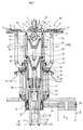
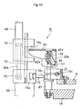
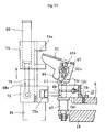
- FIGs. 2 and 3 are sectional views of the scrubbing station E in accordance with the present invention.
- a substrate chuck 6 is slidably mounted on a upper-rotary housing 10 by way of sliders 9.
- the substrate chuck 6 is of annular shape and divided into three pieces.
- the chuck diameter of the substrate chuck 6 is scalable, as can be seen from Figs. 4 and 5.
- the substrate chuck 6 has a self-centering clamp groove 4 formed along inner circumference thereof so as to chuck the entire periphery of the thin substrate 1.
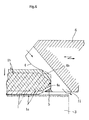
- Fig. 6 is a partially enlarged sectional view of the self-centering clamp groove 4 which is formed in the inner circumference of the substrate chuck 6.
- the self-centering clamp groove 4 is defined by the inside surface 4a abutting against the circumference of the substrate 1, a jaw 5 positioned at the lower end of the inside surface 4a for supporting the lower tapered surface of the substrate 1, and an upper slide oblique surface 4b positioned above the jaw 5.
- the upper slide oblique surface 4b is slightly curved to be followed by the inside surface 4a and has such sectional configuration as the surface line is slightly waved in S-shape.
- the periphery of the substrate 1 received in the self-centering clamp groove 4 slightly slides along the upper slide oblique surface 4b and fits within the inside surface 4a, and the tapered peripheral portion of the substrate 1 is supported by the jaw 5.
- the jaw 5 is slightly engaged with the lower tapered surface of the substrate 1, and does not project downwardly of the surface to be scrubbed 1a (the lower face) of the substrate 1.
- the surface to be scrubbed will hereinafter be called "scrub surface” for convenience.
- a plurality of fluid drain through-holes 11 are formed at certain intervals in the vicinity of the inner circumference of the substrate chuck 6, and the major axis of the elliptical through-hole 11 extends along the tangent line of the self-centering clamp groove 4.
- the fluid drain through-hole 11 extends downwardly obliquely from the inside surface to the lower surface of the substrate chuck 6. Fluid discharged onto the back pressure applied surface 1b of the substrate 1 is smoothly drained through the fluid drain through-holes 11 to the lower side of the substrate chuck 6.
- a slide member 12a of the scalable guide 12 is slidably held in a slide opening 71a formed in a roller mounting block 70a of the adjacent substrate chuck piece 6.
- the clearance between adjacent substrate chuck pieces 6 is expanded by inserting an expansion cylinder head 14 between expansion rollers 13 provided at the ends of the adjacent pair of the substrate chuck pieces 6.
- the slide member 12a is moved away from the slide opening 71a.
- the scalability of the substrate chuck 6 is slidably adjusted by sliders 9 provided on the lower side of the substrate chuck 6.
- the chuck diameter of the substrate chuck 6 is increased by the expansion cylinder heads 14 as described above, and is reduced by chuck diameter reduction cylinders 15 each provided in a position opposite the expansion cylinder head 14. That is, the substrate chuck 6 is pushed inward by the operation of the chuck diameter reduction cylinders 15, and the slide members 12a are pushed back into the slide openings 71a, whereby the entire substrate chuck 6 is closed as shown in Fig. 5. At this time, the expansion cylinder heads 14 are pulled back.
- the substrate chuck 6 When the substrate chuck 6 is closed to chuck the periphery of the substrate chuck 1 within the self-centering clamp groove 4, one of the scalable guides 12 is locked by a lock mechanism H. Therefore, the substrate chuck 6 does not open by centrifugal force generated by the rotation of the substrate chuck 6.
- the lock mechanism will be described later.
- the upper rotary housing 10 is connected to a rotary drum 17 by means of a rotary head cover 16.
- a coupled driving pulley 18 is mounted to the rotary drum 17 and connected to a driving pulley 20 of a motor 21 for rotating substrate by means of a driving belt 19. Accordingly, the torque of the motor 21 for rotating substrate is transmitted to the coupled driving pulley 18 to rotate the substrate chuck 6.
- a positioning cam 22 is mounted to the coupled driving pulley 18.
- a positioning cam follower 23 is adapted to be fitted into the groove of the positioning cam 22 so that the substrate chuck 6 can be forcibly stopped in a predetermined position at any time. To ensure that the positioning cam follower 23 is exactly received in the groove of the positioning cam 22 at any time, the stopping position is always monitored by a positioning sensor. This is well known in the art, and therefore will not be described in detail herein.
- a stationary housing 24 is fitted around the rotary drum 17, and rotatably supports the rotary drum 17 by means of a bearing.
- a stationary splash protect ion cover 25 is provided on top of the stationary housing 24.
- Posts 27 are erected upwardly of a base plate 26, and a stationary block 29 is fixed on top of the posts 27.
- a stationary head cover 28 is mounted on top of the stationary block 29, and covers the rotary head cover 16.
- a substrate support cylinder rod 30 is slidably inserted into the center of the stationary block 29, and is elevatably driven by a substrate support operation cylinder 31 disposed below the stationary block 29.
- a substrate support intermediate member 32 having a V-shaped cross section is mounted on top of the substrate support cylinder rod 30, and substrate support rods 33 are erected upwardly of the substrate support intermediate member 32.
- substrate support rods 33 are provided, and their tip portions are covered with support heads 35 with cushion members 34 being interposed.
- a fluid receiving member 36 having a V-shaped cross section is provided below a cylindrical brush 3.
- Brush elevation bars 37 are slidably inserted into the stationary block 29.
- a brush elevation cylinder 38 is disposed at the lower end of the brush elevation bars 37 to raise and lower the brush elevation bars 37.
- a brush mounting member 39 is mounted to rotatably support the cylindrical brush 3 thereon.
- the cylindrical brush 3 is rotatably supported around a rotary shaft 40, at one end of which a coupled brush driving pulley 41 is attached.
- a brush driving belt 42 is suspended on the coupled brush driving pulley 41, and is connected to a brush driving pulley 43 of a brush driving motor 44 to transmit the torque of the brush driving pulley 43 to the cylindrical brush 3.
- a highly water-absorptive buff is used as the cylindrical brush 3, but not limited thereto. Long-haired or short-haired brushes are also used, depending on applications.
- a drain pipe 45 is provided in the stationary block 29, and drains the fluid fallen onto the stationary block 29.
- a wash fluid jet nozzle 46 is connected to a wash fluid supply pipe 47 provided in the stationary block 29 to jet the wash fluid against the cylindrical brush 3 from the tip of the wash fluid jet nozzle 46.
- high purity water is used as the wash fluid, but not limited thereto.
- Liquid such as alcohols, and inert gases such as nitrogen and argon gases are also usable as the wash fluid.
- electrostatic charge may be built up in the substrate 1. Therefore, it is desirable to use high purity water with lower electric conductivity which contains carbon dioxide gas, in terms of the prevention of electrostatic charge.
- a gas is used as the wash fluid, it is also desirable to previously treat the gas by means of an ionizer.
- a back pressure paddle 7 disposed right above the cylindrical brush 3 is adapted to be moved upwardly and downwardly with respect to the substrate 1, and is formed with a fluid jet outlet 7a at the center thereof.
- the fluid jet outlet 7a may be formed as a single hole opposing to the center of the substrate 1 and positioned right above the cylindrical brush 3, as a plurality of holes provided in a line along the cylindrical brush 3, or as a slit.
- a slit-shaped fluid jet outlet 7a is formed in the lower surface of the back pressure paddle 7, and the back pressure fluid is discharged therefrom.
- an inert gas such as nitrogen gas or liquid such as high purity water is used as the back pressure fluid.
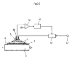
- a displacement sensor 49 is disposed within the back pressure paddle 7.
- the output from the displacement sensor 49 is input to one terminal of a comparator 50, and compared with a reference voltage.
- the output from the comparator 50 indicative of a displacement amount is input to a driver 51.
- the driver 51 drives a regulator 52 to regulate the jet pressure of the back pressure fluid 2 discharged from the fluid jet outlet 7a.
- a fluid supply source 53 supplies the fluid 2 to the regulator 52 at a constant pressure.
- FIG. 20 A block diagram illustrating the back pressure regulation mechanism is shown in Fig. 20.
- a lamp 86 such as deuterium lamp, mercury lamp, or barrier lamp is used as the charge removal means J, but not limited thereto. Electrostatic charge may be otherwise removed: (1) with an ionizer using corona discharge; (2) with isotopes; (3) with electron beam; (4) with plasma; and (5) with soft X-radiation.
- the use of lamp is the most convenient among these means, and does not generate harmful dust particles.
- This embodiment takes an example of dust-free charge removal mechanism using the aforementioned lamp for generating ultraviolet ray.
- the charge removal mechanism using lamps 88 and 89 will be briefly described herein.
- the lamps 88 and 89 generate ultraviolet ray.
- a short wavelength ultraviolet ray serves to electrically neutralize the surface 1a of the substrate 1 to be made dust-free by ionizing the ambient gas at the location of the irradiation.
- a long wavelength ultraviolet ray generates photoelectrons to remove electrostatic charge from the substrate 1. That is, the ultraviolet ray generates photoelectrons from its sealed glass tube to remove positive electric charge from the substrate 1, and impinges on a charged body (substrate 1) which itself generates photoelectrons to remove negative electric charge.
- the low pressure mercury lamp is suitable for the use of short wavelength ultraviolet ray.
- ultraviolet ray When ultraviolet ray is used for the charge removal, it is important to directly apply the ultraviolet ray onto the charged substrate 1. Since the generation of photoelectrons is enhanced with an increased energy, it is desirable to use short-wavelength and high-intensity ultraviolet ray.
- the lock mechanism H grips the guide lock 12c of the scalable guide 12 to prevent the substrate chuck 6 from being expanded by the centrifugal force generated by the rotation of the substrate chuck 6.
- a pair of roller mounting blocks 70a and 70b are provided at the juncture 6a of the substrate chuck pieces 6.
- a locking block 70c is integrally connected to the roller mounting block 70a, and an isolation gap 68 is formed between the roller mounting block 70a and locking block 70c.
- a locking shaft base 67 is erected on the top of the upper rotary housing 10, and extends through to the opening side of the locking block 70c.
- An operation lever 61 of a reversed U-shape is provided above the locking block 70c.
- a lock shaft 66 extends through a horizontal lock shaft 62 disposed parallel to the operation lever 61, and is height-adjustably fixed by an adjusting nut 62a.
- the lock shaft 66 and lock shaft base 67 are integrally formed.
- Lock lever mounting bars 62b are fixed to the horizontal lock shaft 62, and swivels with the pivotal movement of the horizontal lock shaft 62.
- Lock rollers 63 are rotatably fixed to roller mounting shafts 64 at the lower end of the lock lever mounting bars to press down the opening side of the locking block 70c.
- a stopping block 72 is mounted on a block mounting platform 65 provided on the periphery of the upper rotary housing 10, and provided with a stop recess 72a at its side wall to receive a stop bolt 73 projecting from the lower portion of the locking block 70c.
- An elevatable lever operation block 74 is provided above the stopping block 72.
- a lock cylinder 60 is fitted into the lever operation block 74.
- a cylinder rod 60a of the lock cylinder 60 is fit into the stopping block 72 to move the lever operation block 74 upwardly and downwardly.
- the lever operation block 74 is formed with a lever operation recess 74a to receive the operation lever 61.
- An elevation guide 75 is erected upwardly of the stopping block 72, and slidably fitted into the lever operation block 74 to guide the lever operation block 74 to be raised or lowered.
- a cassette 54 accommodating multiple substrates 1 is prepared at the loader B, and an empty cassette 54 is provided at the unloader D.
- the transportation robot C takes a substrate 1 out of the loader B, and supplies the substrate 1 to the scrubbing station E.
- the substrate chuck 6 is expanded by means of the expansion head 14 as shown in Fig. 4, and the substrate 1 clamped at its periphery by the transportation robot C is inserted into the expanded chuck 6.
- Fig. 6 is enlarged view illustrating the current structural relation between the substrate chuck 6 and substrate 1. As shown in phantom in Fig.
- the substrate 1 is supported within the inside surface 4a of the substrate chuck 6 in a position slightly upper than the self-centering clamp groove 4.
- the periphery of the substrate 1 is brought into contact with the upper slide oblique surface 4b of the self-centering clamp groove 4, and then moves downwardly along the upper slide oblique surface 4b so as to be exactly fitted into the inside surface 4a.
- the jaw 5 of the substrate chuck 6 abuts against the tapered lower face of the periphery of the substrate 1, and therefore the lower surface of the substrate chuck 6 does not project downwardly of the scrub surface 1a of the substrate 1.
- the substrate support rods 33 are further lowered by means of the substrate support operation cylinder 31 so as to be apart from the scrub surface 1a of the substrate 1.
- the transportation robot C returns to the home position, and stands by for the completion of the scrubbing of the substrate 1 to remove the substrate scrubbed from the scrubbing station E.
- the back pressure paddle 7 moves down and stops right above the back pressure surface 1b of the substrate 1.
- the back pressure paddle 7 jets the back pressure fluid 2 against the back pressure surface 1b of the substrate 1 to apply back pressure thereon.
- the cylindrical brush 3 standing by below the substrate 1 is moved upwardly by means of the brush elevation cylinder 38 so as to be brought into contact with the scrub surface 1a of the substrate 1.
- wash liquid is jetted from the wash fluid jet nozzle 46 toward the cylindrical brush 3 to wet the cylindrical brush 3.
- the cylindrical brush 3 rotated by means of the brush driving motor 44 scrubs the scrub surface 1a of the substrate 1.
- the upper rotary housing 10 is rotated by means of the substrate rotating motor 21 to rotate the substrate 1 chucked by the substrate chuck 6 within the plane of the substrate 1. Since the scrub surface 1a of the substrate 1 brought into line contact with the cylindrical brush 3 is rotated within the plane thereof, the entire scrub surface 1a of the substrate 1 is scrubbed by the cylindrical brush 3 at a high speed.
- the entire scrub surface can be scrubbed without leaving almost any unscrubbed surface portion.
- a gas such nitrogen gas or liquid such as high purity water is used as the back pressure fluid 2 jetted from the back pressure paddle 7.
- a liquid is used as the back pressure fluid 2
- a plurality of fluid drain through-holes 11 extending from the inside surface 4a to the lower surface of the substrate chuck 6 are provided along the self-centering clamp groove 4 and, therefore, during the rotation of the substrate chuck 6, the back pressure fluid on the substrate 1 is drained through the fluid drain through-holes 11 to the lower side of the substrate chuck 6, and no back pressure fluid remains undrained.
- the fluid drain through-holes 11 are of oval or elliptical configuration, and the major axis of the through-hole extends along the tangent line of the annular self-centering clamp groove 4.
- the lock mechanism H When the substrate chuck 6 is rotated during the scrubbing, the substrate chuck pieces 6 are to be radially moved by the centrifugal force so that the chuck diameter of the self-centering groove 4 will be increased. However, the chuck diameter reduction cylinder 15 reduces the chuck diameter of the substrate chuck 6. Thereafter, the lever operation block 74 is raised by means of the lock cylinder 60, and the operation lever 61 engaged with the lever operation recess 74a is pivoted upwardly.
- the lock lever mounting bars 62b are swiveled clockwise (in the figure) about the horizontal lock shaft 62 fixed to the operation lever 61.
- the lock roller 63 is forcibly pressed down on the surface of the locking block 70c to shrink the gap of the locking slit 69, whereby the guide lock 12c inserted into the locking through-hole 71c is firmly gripped.
- the lock roller 63 maintains the guide lock 12c in the locked state by the resilience, or the clicking action of the locking block 70c.
- the operation lever 61 and the stopping bolt 73 are disengaged respectively from the lever operation recess 74a and the stop recess 72a, and the substrate 1 is rotated with the substrate chuck 6 being kept in a locked state as shown in the figure. Therefore, the lock cylinder 60 and members mounted thereon do not rotate with the substrate chuck 6.
- the lock mechanism H is rotated with the substrate chuck 6 in the locked state. However, since only the members necessary for locking are mounted on the substrate chuck 6, the reduced weight of the substrate chuck 6 facilitates the rotation of the substrate chuck 6.
- the displacement sensor 49 provided on the back pressure paddle 7 always detects the distance between the substrate 1 and the displacement sensor 49.
- the flow rate of the back pressure fluid 2 jetted against the back pressure surface 1b from the back pressure paddle 7 is controlled so that the distance between the substrate 1 and the displacement sensor 49 is kept constant, based on the feedback from the displacement sensor 49. Therefore, the contact pressure of the cylindrical brush 3 is properly balanced with the back pressure on the central portion of the substrate 1, whereby the entire scrub surface 1a of the substrate 1 can be sufficiently scrubbed.
- the slit of the fluid jet outlet 7a of the back pressure paddle 7 extends along the cylindrical brush 3, so that the back pressure is linearly applied onto the substrate 1. Therefore, the scrub surface 1a of the substrate 1 kept afloat with its periphery being supported by the self-centering clamp groove 4 can be scrubbed with the cylindrical brush 3 by applying sufficient pressure thereto.
- the brush elevation cylinder 38 performs a reverse operation and moves downwardly, whereby the cylindrical brush 3 moves away from the scrub surface 1a of the substrate 1.
- the brush driving motor 44 is turned off to stop the rotation of the cylindrical brush 3.
- the discharge of the back pressure fluid 2 from the back pressure paddle 7 is stopped to cease applying the back pressure onto the substrate 1, and the back pressure paddle 7 is moved upwardly.
- the jetting of wash fluid from the wash fluid jet nozzle 46 is stopped.
- the revolution of the substrate rotating motor 21 is increased, thereby increasing the rotation speed of the upper rotary housing 10. Accordingly, the liquid adhering on the surface of the substrate 1 is blown off by the centrifugal force and drained through the fluid drain through-holes 11, and thus the substrate 1 is dried.
- Electrostatic charge may be generated on the substrate 1 by the friction caused by the contact between substrate 1 and rotating cylindrical brush 3 and/or the wash liquid such as high purity water during the scrubbing operation, and also by the friction caused by the contact between the substrate 1 and the ambient air during the drying operation by the high speed revolution.
- the electrostatic charge on the substrate 1 can be removed by the aforementioned charge removal mechanism, that is, by irradiating ultraviolet ray on the substrate 1 with the charge removal means J during and after the drying operation.
- the substrate chuck 6 After the drying and charge removal of the substrate 1, the substrate chuck 6 is stopped rotating at an exact position such that the operation lever 61 is aligned with the lever operation block 74.
- the positioning sensor 23 To precisely control the stop position of the operation lever 61, the positioning sensor 23 detects the rotational position of the upper-rotary housing 10 to fit the positioning cam follower 23 into the positioning cam 22.
- the lock cylinder 60 When the operation lever 61 is stopped at the position aligning with the lever operation block 74 and the operation lever 61 is received into the lever operation recess 74a, the lock cylinder 60 performs a reverse operation to lower the lever operation block 74, thereby pressing down the operation lever 61 fitted into the lever operation recess 74a. Further, the lock lever mounting bars 62b are swiveled counterclockwise (in the figure) about the horizontal lock shaft 62 fixed to the operation lever 61, so that the lock roller 63 is disengaged from the surface of the locking block 70c. Accordingly, the locking slit 69 is widened by the resilient force of the locking block 70c, and the guide lock 12c is released from the gripping of the locking through-hole 71c to become slidable.
- the expansion cylinder head 14 is inserted again between the pair of the expansion rollers to expand the clearance 6a as shown in Fig. 4. Accordingly, the diameter defined by the inside surface 4a of the substrate chuck 6 is increased, whereby the substrate 1 is released from the self-centering clamp groove 4.
- the substrate support operation cylinder 31 operates again to raise the substrate support rods 33, so that the cushion members 34 provided at the tips of the substrate support rods 33 are brought into contact with the scrub surface 1a of the substrate 1. At this time, the support heads 35 are slightly deformed by the spring force of the cushion members 34.
- the substrate chuck 6 After the scrub surface 1a of the substrate 1 is supported by the support heads 35, the substrate chuck 6 is expanded as described above, and the substrate 1 is released from the self-centering clamp groove 4 of the substrate chuck 6 and supported only by the support heads 35.
- the substrate support operation cylinder 31 is operated with this situation to eject the substrate 1 upwardly of the substrate chuck 6.
- the ejected substrate 1 is removed by the transportation robot C.
- the transportation robot C once returns to the home position, and then transports the substrate 1 to the unloader D. At this time, electrostatic charge generated by the friction between the substrate 1 and the ambient air is removed by the ultraviolet ray generating lamp 88 provided as a charge removal means at the home position of the transportation robot C.
- the substrate 1 is inserted into the empty cassette 54 mounted on the unloader D.
- the one-face scrubbing (or back-face scrubbing) of one substrate is completed.
- both-face scrubbing (or front- and back-face scrubbing) may be required depending on the types of substrates 1 or by a request from manufacturing sites.
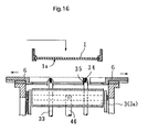
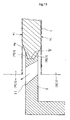
- a substrate chuck 6 for both-face scrubbing has a clamp portion, the width of which is less than the thickness of a substrate 1.
- a self-centering clamp groove 4 is formed on the inside circumference of the clamp portion, and the tapered periphery of the substrate 1 is chucked by the substrate supporting jaws 5a and 5b of a jaw member 5.
- Brushes 3a and 3b movable upwardly and downwardly are brought into contact with the both faces of the substrate 1 to simultaneously scrub the both faces of the substrate 1. Accordingly, the difference between the both-face scrubbing and one-face scrubbing shown in the first embodiment is that the back pressure paddle 7 is replaced by an upper side brush 3b.
- the scrubbed substrate 1 is removed from the scrubbing station E, transported to an unloader D, and inserted to an empty cassette 54 mounted on the unloader D by a transportation robot C.
- charge removal means J are disposed on the both sides of the substrate 1 to apply ultraviolet ray onto the both faces of the substrate 1.
- the method and apparatus for scrubbing substrate of the present invention present an excellent ability to scrub either face or both faces of a semiconductor substrate. Since the contact pressure of a brush is balanced with an appropriate back pressure or the contact pressure of another brush provided on the side of the front face of the substrate during the scrubbing operation, the warpage of the central portion of the substrate can be prevented, whereby even the central portion of the substrate can be sufficiently scrubbed. In addition, since chuck jaw does not project outwardly of the scrub surface and therefore the cylindrical brush can be applied onto the substrate over the chuck jaw, no portion of the substrate remains unscrubbed.
- fluid drains are provided along a clamp groove, fluid on the substrate can be smoothly drained from the fluid drains by centrifugal force generated by the rotation of the substrate chuck and the substrate, and no fluid on the substrate remains undrained. Therefore, the front face as well as the back face of the substrate can be always kept clean.
Landscapes
- Engineering & Computer Science (AREA)
- Physics & Mathematics (AREA)
- Condensed Matter Physics & Semiconductors (AREA)
- General Physics & Mathematics (AREA)
- Manufacturing & Machinery (AREA)
- Computer Hardware Design (AREA)
- Microelectronics & Electronic Packaging (AREA)
- Power Engineering (AREA)
- Mechanical Engineering (AREA)
- Cleaning Or Drying Semiconductors (AREA)
- Cleaning In General (AREA)
Abstract
Description
- The presentinvention relates to method and apparatus for scrubbing either face or both faces of a substrate with a cylindrical brush while chucking only the periphery of the substrate.
- Recently, semiconductor devices have been evolved from very large scale integration (VLSI) into ultra large scale integration (ULSI). On a surface of a semiconductor substrate, very minute circuits are densely formed using a precision photolithographic technique. In the production process, microscopic dust particles adhering on the surface of the semiconductor substrate will result in defective semiconductor circuits and reduce the production yield. The production cost steeply rises, as the degree of integration of semiconductor devices increases. Therefore, an improvement in the production yield will largely contribute to the cost reduction, and the removal of dust particles is a very important subject.
- At the production site of semiconductor devices, although the cleaning of the front face of a semiconductor substrate on which microcircuits are formed is strictly controlled, control on the cleaning of the back face is not so strict at present. During the production processes, the back face of the semiconductor substrate is brought into contact with suction bases of equipment and handling devices, and becomes contaminated. The contamination of the back face is found to be one of the causes of the contamination of the front face.
- Though sufficient cleaning of the back face of the semiconductor substrate has recently been added to the production process, there still exist problems as follows:
- (1) Since microcircuits are densely formed on the front face of a semiconductor substrate as previously mentioned, the substrate cannot be supported at the front face thereof for the scrubbing of the back face thereof. Accordingly, the semiconductor substrate has to be supported by chucking the periphery of the substrate with a chuck jaw without supporting a central portion of the front face of the substrate for the scrubbing of the back face. However, since a chuck jaw for chucking the periphery of the substrate slightly projects outwardly of the scrub face of the substrate, a disk brush as shown in Fig. 21 which has a small scrubbing area and hence is of an insufficient scrubbing ability is conventionally used for the scrubbing.
- (2) When the back face of the semiconductor substrate is scrubbed with a scrubbing means such as a brush with its periphery being chucked by the chuck jaw as described above, the thin semiconductor substrate is warped by the contact pressure of the brush, so that a central portion of the substrate cannot be sufficiently scrubbed.
- (3) Since the chuck jaw projects outwardly of the scrub surface of the semiconductor substrate as described above, peripheral portions of the substrate adjacent the projections of the chuck jaw cannot be sufficiently scrubbed, and some part of the scrub surface remains unscrubbed.
- Another problem associated with the production of semiconductor devices is dust particles suspended in the air. Although a production apparatus for semiconductor devices which is related to the present invention is used in a clean room and the amount of dust particles suspended in the air is significantly reduced, there exists a very small amount of suspended dust particles. After the scrubbing of the substrate, these dust particles will adhere onto the surfaces of the substrate charged by static electricity, and the scrubbed surface of the substrate will become contaminated.
- In view of the problems associated with the prior art, it is an object of the present invention to provide method and apparatus for scrubbing a substrate which present an enhanced scrubbing ability.
- It is another object of the present invention to provide method and apparatus for scrubbing a substrate which prevent a central port ion of the semiconductor substrate from being warped by the contact pressure of a brush during the scrubbing operation so as to sufficiently scrub even the central portion.
- It is still another object of the present invention to provide method and apparatus for scrubbing a substrate which are capable of scrubbing even peripheral portions of the substrate lying very close to the projections of a chuck jaw for chucking the substrate.
- It is a further object of the present invention to provide method and apparatus for scrubbing a substrate which prevent suspended dust particles from adhering onto the substrate by removing electrostatic charge after the scrubbing of the substrate.
- According to a first aspect of the present invention, there is provided a method for scrubbing a substrate comprising the step of scrubbing one face of the substrate with a cylindrical rotary brush while applying back pressure to the substrate by jetting a fluid for generating back pressure against the other face of the substrate.
- With this method, while only the periphery of the substrate is chucked, even a central portion of the substrate can forcibly be scrubbed by virtue of the back pressure applied thereto, and no port ion of the surface remains unscrubbed.
- According to a second aspect of the present invention, there is provided a method for scrubbing a substrate comprising the step of scrubbing both faces of the substrate with cylindrical rotary brushes disposed on the both sides of the substrate symmetrically with respect to the substrate.
- With this method, the pressure applied to one face of the substrate is balanced with the pressure applied to the other and, hence, even a central port ion which is difficult to scrub can be effectively scrubbed without warpage of the substrate.
- Preferably, the method according to the first or second aspect of the present invention further comprising the step of, after scrubbing the substrate, drying the substrate and then removing electrostatic charge from the substrate with a charge removal means.
- The substrate is brought into contact with a cylindrical rotary brush and a wash liquid when scrubbed, and then centrifugally dried by rotating the substrate at a high speed. At this time, the friction caused by the contact between the substrate and the cylindrical rotary brush and/or wash liquid (especially where the wash liquid is high purity water) and between the substrate and the ambient air sometimes generates electrostatic charge on the substrate. Such electrostatic charge can be effectively removed by the aforementioned charge removing means. This prevents dust particles suspended in the air from adhering onto the substrate and enables the substrate to be kept clean after the scrubbing.
- According to a third aspect of the present invention, there is provided an apparatus for scrubbing a substrate comprising: a substrate chuck adapted to surround the substrate and having a clamp groove formed therein for receiving a periphery of the substrate: a cylindrical rotary brush adapted to contact a scrub face of the substrate for scrubbing the scrub face from one end to the other; a back pressure paddle for jetting fluid against an opposing face of the substrate to apply back pressure to the substrate; and a rotation mechanism for rotating one of the substrate chuck and the cylindrical rotary brush within a plane parallel to the substrate wherein said substrate chuck includes chucking jaws projecting inwardly from the clamp groove of the substrate chuck to support the substrate such that the entire scrub face is exposed to the cylindrical rotary brush, the jaws are not exposed to the brush, and the opposing face is exposed to the back pressure paddle.
- With this apparatus, the substrate is scrubbed with only the periphery thereof being chucked while a high contact pressure is applied to a central portion of the substrate; thus, even the central portion which has been unable to be sufficiently scrubbed by a conventional apparatus can be effectively scrubbed. Since the chuck jaw for chucking the periphery of the substrate is adapted to be positioned inward relative to the face to be scrubbed of the substrate, the brush never contacts the chuck jaw. Therefore, the brush can be moved extensively even beyond the circumference of the substrate to scrub the substrate. This ensures an improved scrubbing efficiency and minimizes an unscrubbed portion remaining in the periphery of the substrate.
- According to a fourth aspect of the present invention, there is provided an apparatus for scrubbing a substrate comprising: a substrate chuck adapted to surround the substrate and having a clamp groove formed therein for receiving a periphery of the substrate; upper and lower cylindrical rotary brushes provided on both sides of the substrate for contacting both faces of the substrate from one end to the other end thereof for scrubbing both faces of the substrate; and a rotation mechanism for rotating one of the substrate chuck and the upper and lower cylindrical rotary brushes within a plane parallel to the substrate, wherein said substrate chuck includes chucking jaws projecting inwardly from the clamp groove of the substrate chuck, such that the substrate is supported therein to expose each substrate face to the respective upper and lower cylindrical rotary brushes.
- With this apparatus, in addition to the advantages of the foregoing apparatus according to the third aspect, the both faces of the substrate can be simultaneously scrubbed.
- According to a fifth aspect of the present invention, there is provided an apparatus for scrubbing a substrate comprising: a substrate chuck adapted to surround the substrate and having a clamp groove formed therein for receiving generally entire peripheral portion of the substrate and fluid drain through-holes provided along the clamp groove and extending from the upper surface to the lower surface thereof; a back pressure paddle for jetting fluid for generating back pressure against the face opposite a face to be scrubbed of the substrate to apply back pressure to the substrate; a cylindrical rotary brush adapted to contact the face to be scrubbed of the substrate for scrubbing the same; and a rotation mechanism for rotating the substrate chuck or the cylindrical rotary brush within a plane parallel to the substrate.
- The fluid for generating back pressure discharged from the back pressure paddle onto the substrate is thrust away toward the circumference of the substrate by the centrifugal force generated by the rotation of the substrate chuck, and is effectively drained from the fluid drain through-holes provided along the clamp groove. Therefore, the upper surface of the substrate can be kept clean.
- In addition, where the water adhering on the substrate is centrifugally removed by rotating the substrate at a high speed after the completion of scrubbing, the water removed is effectively drained from the fluid drain through-holes.
- According to a sixth aspect of the present invention, there is provided an apparatus for scrubbing a substrate comprising: a substrate chuck adapted to surround the substrate and having a clamp groove formed therein for receiving generally entire peripheral portion of the substrate and fluid drain through-holes provided along the clamp groove and extending from the upper surface to the lower surface thereof; upper and lower cylindrical rotary brushes provided on both sides of the substrate and adapted to contact both faces of the substrate, respectively, for scrubbing the both surfaces of the substrate; and a rotation mechanism for rotating the substrate chuck or the upper and lower cylindrical rotary brushes within a plane parallel to the substrate.
- With this apparatus, like the fifth case, wash water will not remain on the upper face of the substrate but is smoothly drained even in a simultaneous two-face scrubbing operation, resulting in an effective simultaneous two-face scrubbing operation.
- Preferably, the apparatus according to any one of the third to sixth aspects of the present invention further comprises a charge removal means provided in a substrate scrubbing station and/or a substrate transporting path for removing electrostatic charge on the substrate after the completion of scrubbing.
- As with the scrubbing methods stated above, the electrostatic charge generated on the substrate during or after scrubbing is effectively removed with the charge removal means. Therefore, the substrate will not attract dust particles suspended in the air and can be kept clean after scrubbing.
- For a more complete understanding of the above and other features and advantages of the invention, reference should be made to the following detailed description of preferred embodiments of the invention, and to the accompanying drawings.
- In the drawings:
- Fig. 1 is a plan view wholly showing a scrubbing apparatus in accordance with the present invention;
- Fig. 2 is a vertical sectional view of a scrubbing station of a scrubbing apparatus in accordance with the present invention;
- Fig. 3 is a vertical sectional view in an orthogonal relation to Fig. 2;
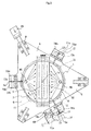
- Fig. 4 is a plan view of the scrubbing station in an opened state;
- Fig. 5 is a plan view of the scrubbing station in a closed state;
- Fig. 6 is an enlarged sectional view for illustrating the relation between a substrate and a clamp groove in accordance with the present invention;
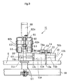
- Fig. 7 is a sectional view of the body portion of the scrubbing station;
- Fig. 8 is a partial plan view of a lock mechanism in accordance with the present invention;
- Fig. 9 is a front view of the lock mechanism shown in Fig. 8;
- Fig. 10 is a partial side elevational view illustrating the lock mechanism before operation;
- Fig. 11 is a partial side elevational view illustrating the lock mechanism after operation;
- Fig. 12 is a schematic sectional view illustrating the scrubbing station before supplying a substrate;
- Fig. 13 is a schematic sectional view illustrating the scrubbing station supplied with a substrate;
- Fig. 14 is a schematic sectional view illustrating the scrubbing station in scrubbing operation;
- Fig. 15 is a schematic sectional view illustrating the scrubbing station in both-face scrubbing operation;
- Fig. 16 is a schematic sectional view illustrating the scrubbing station before supplying a substrate in both-face scrubbing process;
- Fig. 17 is a schematic sectional view illustrating the scrubbing station after supplying the substrate in both-face scrubbing process;
- Fig. 18 is a schematic sectional view illustrating the scrubbing station in both-face scrubbing operation;
- Fig. 19 is an enlarged sectional view for showing the relation between the substrate and clamp groove in both-face scrubbing process;
- Fig. 20 is a block circuit diagram illustrating a displacement sensor used in the present invention; and
- Fig. 21 is a schematic representation of a conventional scrubbing apparatus.
- The present invention will now be described in detail by way of the embodiments illustrated in the attached drawings. In these embodiments is used a semiconductor wafer as an example of a substrate. However, the present invention is also applicable to other thin plates such as glass plate, alumina plate, crystal plate, ceramic plate, sapphire plate, aluminum disc and the like. Referring to Fig. 1, a scrubbing apparatus A includes a scrubbing station E for scrubbing a
substrate 1, a transportation robot C for transporting thesubstrate 1 into and out of the scrubbing station E, a loader B for supplying thesubstrate 1 to the transportation robot C, an unloader D for storing a scrubbedsubstrate 1, a controller F for controlling the entire apparatus, and a main body G for accommodating these components. - The loader B prepares an
unscrubbed substrate 1 accommodated in acassette 54, which is raised or lowered step by step in synchronization with the take-out operation of the transportation robot C to move theunscrubbed substrate 1 into a predetermined position. - The unloader D prepares an
empty cassette 54 for accommodating a scrubbedsubstrate 1 to be transported by the transportation robot C after the back-face scrubbing at the scrubbing station E. Thecassette 54 is raised or lowered step by step in synchronization with the supply of thesubstrate 1. - The transportation robot C takes the
unscrubbed substrate 1 out of the loader B to supply thesubstrate 1 to the scrubbing station E. After the back-face scrubbing at the scrubbing station E, the transportation robot C removes the scrubbedsubstrate 1 from the scrubbing station E to transport thesubstrate 1 to the unloader D. - At the location of the transportation robot C, an ultraviolet
ray generating lamp 88 is provided as a dust removal means J. The operation of the ultravioletray generating lamp 88 will be described later. - The structures of the loader B, unloader D, and transportation robot C are well known in the art, and therefore will not be described in detail herein.
- Figs. 2 and 3 are sectional views of the scrubbing station E in accordance with the present invention. A
substrate chuck 6 is slidably mounted on a upper-rotary housing 10 by way ofsliders 9. - The
substrate chuck 6 is of annular shape and divided into three pieces. The chuck diameter of thesubstrate chuck 6 is scalable, as can be seen from Figs. 4 and 5. Thesubstrate chuck 6 has a self-centeringclamp groove 4 formed along inner circumference thereof so as to chuck the entire periphery of thethin substrate 1. - Fig. 6 is a partially enlarged sectional view of the self-centering
clamp groove 4 which is formed in the inner circumference of thesubstrate chuck 6. The self-centeringclamp groove 4 is defined by theinside surface 4a abutting against the circumference of thesubstrate 1, ajaw 5 positioned at the lower end of theinside surface 4a for supporting the lower tapered surface of thesubstrate 1, and an upper slideoblique surface 4b positioned above thejaw 5. In the embodiment shown in Fig. 6, the upper slideoblique surface 4b is slightly curved to be followed by theinside surface 4a and has such sectional configuration as the surface line is slightly waved in S-shape. Therefore, the periphery of thesubstrate 1 received in the self-centeringclamp groove 4 slightly slides along the upper slideoblique surface 4b and fits within theinside surface 4a, and the tapered peripheral portion of thesubstrate 1 is supported by thejaw 5. Thejaw 5 is slightly engaged with the lower tapered surface of thesubstrate 1, and does not project downwardly of the surface to be scrubbed 1a (the lower face) of thesubstrate 1. The surface to be scrubbed will hereinafter be called "scrub surface" for convenience. - A plurality of fluid drain through-
holes 11 are formed at certain intervals in the vicinity of the inner circumference of thesubstrate chuck 6, and the major axis of the elliptical through-hole 11 extends along the tangent line of the self-centeringclamp groove 4. The fluid drain through-hole 11 extends downwardly obliquely from the inside surface to the lower surface of thesubstrate chuck 6. Fluid discharged onto the back pressure appliedsurface 1b of thesubstrate 1 is smoothly drained through the fluid drain through-holes 11 to the lower side of thesubstrate chuck 6. - Three pieces of the
substrate chuck 6 are connected by means ofscalable guides 12 fixed ontoroller mounting blocks 70b. Aslide member 12a of thescalable guide 12 is slidably held in aslide opening 71a formed in aroller mounting block 70a of the adjacentsubstrate chuck piece 6. As shown in Fig. 4, the clearance between adjacentsubstrate chuck pieces 6 is expanded by inserting anexpansion cylinder head 14 betweenexpansion rollers 13 provided at the ends of the adjacent pair of thesubstrate chuck pieces 6. At this time, theslide member 12a is moved away from theslide opening 71a. - The scalability of the
substrate chuck 6 is slidably adjusted bysliders 9 provided on the lower side of thesubstrate chuck 6. The chuck diameter of thesubstrate chuck 6 is increased by theexpansion cylinder heads 14 as described above, and is reduced by chuckdiameter reduction cylinders 15 each provided in a position opposite theexpansion cylinder head 14. That is, thesubstrate chuck 6 is pushed inward by the operation of the chuckdiameter reduction cylinders 15, and theslide members 12a are pushed back into theslide openings 71a, whereby theentire substrate chuck 6 is closed as shown in Fig. 5. At this time, theexpansion cylinder heads 14 are pulled back. - When the
substrate chuck 6 is closed to chuck the periphery of thesubstrate chuck 1 within the self-centeringclamp groove 4, one of thescalable guides 12 is locked by a lock mechanism H. Therefore, thesubstrate chuck 6 does not open by centrifugal force generated by the rotation of thesubstrate chuck 6. The lock mechanism will be described later. - The upper
rotary housing 10 is connected to arotary drum 17 by means of arotary head cover 16. A coupled drivingpulley 18 is mounted to therotary drum 17 and connected to a drivingpulley 20 of a motor 21 for rotating substrate by means of a drivingbelt 19. Accordingly, the torque of the motor 21 for rotating substrate is transmitted to the coupled drivingpulley 18 to rotate thesubstrate chuck 6. Apositioning cam 22 is mounted to the coupled drivingpulley 18. Apositioning cam follower 23 is adapted to be fitted into the groove of thepositioning cam 22 so that thesubstrate chuck 6 can be forcibly stopped in a predetermined position at any time. To ensure that thepositioning cam follower 23 is exactly received in the groove of thepositioning cam 22 at any time, the stopping position is always monitored by a positioning sensor. This is well known in the art, and therefore will not be described in detail herein. - A
stationary housing 24 is fitted around therotary drum 17, and rotatably supports therotary drum 17 by means of a bearing. - A stationary splash protect
ion cover 25 is provided on top of thestationary housing 24.Posts 27 are erected upwardly of abase plate 26, and astationary block 29 is fixed on top of theposts 27. - A
stationary head cover 28 is mounted on top of thestationary block 29, and covers therotary head cover 16. - A substrate
support cylinder rod 30 is slidably inserted into the center of thestationary block 29, and is elevatably driven by a substratesupport operation cylinder 31 disposed below thestationary block 29. - A substrate support
intermediate member 32 having a V-shaped cross section is mounted on top of the substratesupport cylinder rod 30, andsubstrate support rods 33 are erected upwardly of the substrate supportintermediate member 32. In this embodiment, foursubstrate support rods 33 are provided, and their tip portions are covered with support heads 35 withcushion members 34 being interposed. - A
fluid receiving member 36 having a V-shaped cross section is provided below acylindrical brush 3. - Brush elevation bars 37 are slidably inserted into the
stationary block 29. Abrush elevation cylinder 38 is disposed at the lower end of the brush elevation bars 37 to raise and lower the brush elevation bars 37. On top of the brush elevation bars 37, abrush mounting member 39 is mounted to rotatably support thecylindrical brush 3 thereon. - The
cylindrical brush 3 is rotatably supported around arotary shaft 40, at one end of which a coupledbrush driving pulley 41 is attached. Abrush driving belt 42 is suspended on the coupledbrush driving pulley 41, and is connected to abrush driving pulley 43 of abrush driving motor 44 to transmit the torque of thebrush driving pulley 43 to thecylindrical brush 3. In this embodiment, a highly water-absorptive buff is used as thecylindrical brush 3, but not limited thereto. Long-haired or short-haired brushes are also used, depending on applications. - A
drain pipe 45 is provided in thestationary block 29, and drains the fluid fallen onto thestationary block 29. A washfluid jet nozzle 46 is connected to a washfluid supply pipe 47 provided in thestationary block 29 to jet the wash fluid against thecylindrical brush 3 from the tip of the washfluid jet nozzle 46. In this embodiment, high purity water is used as the wash fluid, but not limited thereto. Liquid such as alcohols, and inert gases such as nitrogen and argon gases are also usable as the wash fluid. - If extremely high purity water is used as a
fluid 2 for generating back pressure, electrostatic charge may be built up in thesubstrate 1. Therefore, it is desirable to use high purity water with lower electric conductivity which contains carbon dioxide gas, in terms of the prevention of electrostatic charge. - If a gas is used as the wash fluid, it is also desirable to previously treat the gas by means of an ionizer.
- A
back pressure paddle 7 disposed right above thecylindrical brush 3 is adapted to be moved upwardly and downwardly with respect to thesubstrate 1, and is formed with afluid jet outlet 7a at the center thereof. Thefluid jet outlet 7a may be formed as a single hole opposing to the center of thesubstrate 1 and positioned right above thecylindrical brush 3, as a plurality of holes provided in a line along thecylindrical brush 3, or as a slit. In this embodiment, a slit-shapedfluid jet outlet 7a is formed in the lower surface of theback pressure paddle 7, and the back pressure fluid is discharged therefrom. - As described above, an inert gas such as nitrogen gas or liquid such as high purity water is used as the back pressure fluid.
- A
displacement sensor 49 is disposed within theback pressure paddle 7. The output from thedisplacement sensor 49 is input to one terminal of acomparator 50, and compared with a reference voltage. The output from thecomparator 50 indicative of a displacement amount is input to adriver 51. Based on the input, thedriver 51 drives aregulator 52 to regulate the jet pressure of theback pressure fluid 2 discharged from thefluid jet outlet 7a. Afluid supply source 53 supplies thefluid 2 to theregulator 52 at a constant pressure. A block diagram illustrating the back pressure regulation mechanism is shown in Fig. 20. - There is now described the charge removal means J disposed at the location of the scrubbing station E and transportation robot C. In this embodiment, a lamp 86 such as deuterium lamp, mercury lamp, or barrier lamp is used as the charge removal means J, but not limited thereto. Electrostatic charge may be otherwise removed: (1) with an ionizer using corona discharge; (2) with isotopes; (3) with electron beam; (4) with plasma; and (5) with soft X-radiation. The use of lamp is the most convenient among these means, and does not generate harmful dust particles. This embodiment takes an example of dust-free charge removal mechanism using the aforementioned lamp for generating ultraviolet ray.
- The charge removal
mechanism using lamps lamps substrate 1 to be made dust-free by ionizing the ambient gas at the location of the irradiation. A long wavelength ultraviolet ray generates photoelectrons to remove electrostatic charge from thesubstrate 1. That is, the ultraviolet ray generates photoelectrons from its sealed glass tube to remove positive electric charge from thesubstrate 1, and impinges on a charged body (substrate 1) which itself generates photoelectrons to remove negative electric charge. - There are three types of mercury lamps - extra-high pressure mercury lamp, high pressure mercury lamp, and low pressure mercury lamp. The low pressure mercury lamp is suitable for the use of short wavelength ultraviolet ray.
- When ultraviolet ray is used for the charge removal, it is important to directly apply the ultraviolet ray onto the charged
substrate 1. Since the generation of photoelectrons is enhanced with an increased energy, it is desirable to use short-wavelength and high-intensity ultraviolet ray. - There is now described the lock mechanism H. The lock mechanism H grips the
guide lock 12c of thescalable guide 12 to prevent thesubstrate chuck 6 from being expanded by the centrifugal force generated by the rotation of thesubstrate chuck 6. A pair ofroller mounting blocks juncture 6a of thesubstrate chuck pieces 6. A lockingblock 70c is integrally connected to theroller mounting block 70a, and anisolation gap 68 is formed between theroller mounting block 70a and lockingblock 70c. A lockingshaft base 67 is erected on the top of the upperrotary housing 10, and extends through to the opening side of thelocking block 70c. Anoperation lever 61 of a reversed U-shape is provided above the lockingblock 70c. Alock shaft 66 extends through ahorizontal lock shaft 62 disposed parallel to theoperation lever 61, and is height-adjustably fixed by an adjustingnut 62a. Thelock shaft 66 andlock shaft base 67 are integrally formed. - Lock
lever mounting bars 62b are fixed to thehorizontal lock shaft 62, and swivels with the pivotal movement of thehorizontal lock shaft 62.Lock rollers 63 are rotatably fixed toroller mounting shafts 64 at the lower end of the lock lever mounting bars to press down the opening side of thelocking block 70c. A stoppingblock 72 is mounted on ablock mounting platform 65 provided on the periphery of the upperrotary housing 10, and provided with astop recess 72a at its side wall to receive astop bolt 73 projecting from the lower portion of thelocking block 70c. An elevatablelever operation block 74 is provided above the stoppingblock 72. Alock cylinder 60 is fitted into thelever operation block 74. Acylinder rod 60a of thelock cylinder 60 is fit into the stoppingblock 72 to move thelever operation block 74 upwardly and downwardly. Thelever operation block 74 is formed with alever operation recess 74a to receive theoperation lever 61. Anelevation guide 75 is erected upwardly of the stoppingblock 72, and slidably fitted into thelever operation block 74 to guide thelever operation block 74 to be raised or lowered. - Referring to Fig. 1 and Figs. 12 to 14, the operation of the present invention will be hereinafter described. A
cassette 54 accommodatingmultiple substrates 1 is prepared at the loader B, and anempty cassette 54 is provided at the unloader D. By the operation of the controller F, the transportation robot C takes asubstrate 1 out of the loader B, and supplies thesubstrate 1 to the scrubbing station E. At this time, thesubstrate chuck 6 is expanded by means of theexpansion head 14 as shown in Fig. 4, and thesubstrate 1 clamped at its periphery by the transportation robot C is inserted into the expandedchuck 6. - At this time, the
substrate support rods 33 raised by means of the substratesupport operation cylinder 31 projects upper than the self-centeringclamp groove 4 of thesubstrate chuck 6 to abut against the scrub surface 1a of thesubstrate 1. When thesubstrate 1 is placed on the support heads 35 of thesubstrate support rods 33, the transportation robot C disengages from the periphery of thesubstrate 1 to release the substrate onto the support heads 35. In turn, the substratesupport operation cylinder 31 performs a reverse operation to move downwardly and stops at a position such that thesubstrate 1 is aligned with the self-centeringclamp groove 4. Fig. 6 is enlarged view illustrating the current structural relation between thesubstrate chuck 6 andsubstrate 1. As shown in phantom in Fig. 6, thesubstrate 1 is supported within theinside surface 4a of thesubstrate chuck 6 in a position slightly upper than the self-centeringclamp groove 4. When thesubstrate chuck 6 is closed by the means of the chuckdiameter reduction cylinder 15, the periphery of thesubstrate 1 is brought into contact with the upper slideoblique surface 4b of the self-centeringclamp groove 4, and then moves downwardly along the upper slideoblique surface 4b so as to be exactly fitted into theinside surface 4a. At this time, thejaw 5 of thesubstrate chuck 6 abuts against the tapered lower face of the periphery of thesubstrate 1, and therefore the lower surface of thesubstrate chuck 6 does not project downwardly of the scrub surface 1a of thesubstrate 1. - After the
substrate 1 is clamped by the self-centeringclamp groove 4 in a self-centering manner, thesubstrate support rods 33 are further lowered by means of the substratesupport operation cylinder 31 so as to be apart from the scrub surface 1a of thesubstrate 1. During this operation, the transportation robot C returns to the home position, and stands by for the completion of the scrubbing of thesubstrate 1 to remove the substrate scrubbed from the scrubbing station E. After the transportation robot C returns from a position above thesubstrate 1 to the home position, theback pressure paddle 7 moves down and stops right above theback pressure surface 1b of thesubstrate 1. On or after moving down, the back pressure paddle 7 jets theback pressure fluid 2 against theback pressure surface 1b of thesubstrate 1 to apply back pressure thereon. Thecylindrical brush 3 standing by below thesubstrate 1 is moved upwardly by means of thebrush elevation cylinder 38 so as to be brought into contact with the scrub surface 1a of thesubstrate 1. At the same time, wash liquid is jetted from the washfluid jet nozzle 46 toward thecylindrical brush 3 to wet thecylindrical brush 3. Thecylindrical brush 3 rotated by means of thebrush driving motor 44 scrubs the scrub surface 1a of thesubstrate 1. During the scrubbing operation by thecylindrical brush 3, the upperrotary housing 10 is rotated by means of the substrate rotating motor 21 to rotate thesubstrate 1 chucked by thesubstrate chuck 6 within the plane of thesubstrate 1. Since the scrub surface 1a of thesubstrate 1 brought into line contact with thecylindrical brush 3 is rotated within the plane thereof, the entire scrub surface 1a of thesubstrate 1 is scrubbed by thecylindrical brush 3 at a high speed. - In addition, since the
cylindrical brush 3 extends outwardly beyond the circumference of thesubstrate 1 toward thesubstrate chuck 6 and thejaw 5 does not project downwardly of the scrub surface 1a as shown in Fig. 6, the entire scrub surface can be scrubbed without leaving almost any unscrubbed surface portion. As described above, a gas such nitrogen gas or liquid such as high purity water is used as theback pressure fluid 2 jetted from theback pressure paddle 7. - If a liquid is used as the
back pressure fluid 2, a plurality of fluid drain through-holes 11 extending from theinside surface 4a to the lower surface of thesubstrate chuck 6 are provided along the self-centeringclamp groove 4 and, therefore, during the rotation of thesubstrate chuck 6, the back pressure fluid on thesubstrate 1 is drained through the fluid drain through-holes 11 to the lower side of thesubstrate chuck 6, and no back pressure fluid remains undrained. - The fluid drain through-
holes 11 are of oval or elliptical configuration, and the major axis of the through-hole extends along the tangent line of the annular self-centeringclamp groove 4. - There is now described the operation of the lock mechanism H. When the
substrate chuck 6 is rotated during the scrubbing, thesubstrate chuck pieces 6 are to be radially moved by the centrifugal force so that the chuck diameter of the self-centeringgroove 4 will be increased. However, the chuckdiameter reduction cylinder 15 reduces the chuck diameter of thesubstrate chuck 6. Thereafter, thelever operation block 74 is raised by means of thelock cylinder 60, and theoperation lever 61 engaged with thelever operation recess 74a is pivoted upwardly. The locklever mounting bars 62b are swiveled clockwise (in the figure) about thehorizontal lock shaft 62 fixed to theoperation lever 61. Thelock roller 63 is forcibly pressed down on the surface of thelocking block 70c to shrink the gap of the locking slit 69, whereby theguide lock 12c inserted into the locking through-hole 71c is firmly gripped. - In this operation, when the
lever operation block 74 is raised by means of thelock cylinder 60, a stoppingbolt 73 is engaged with the stoppingrecess 72a. Therefore, excessively large bending force is not exerted on thesubstrate chuck 6. - The
lock roller 63 maintains theguide lock 12c in the locked state by the resilience, or the clicking action of thelocking block 70c. When thesubstrate chuck 6 is rotated with this situation, theoperation lever 61 and the stoppingbolt 73 are disengaged respectively from thelever operation recess 74a and thestop recess 72a, and thesubstrate 1 is rotated with thesubstrate chuck 6 being kept in a locked state as shown in the figure. Therefore, thelock cylinder 60 and members mounted thereon do not rotate with thesubstrate chuck 6. The lock mechanism H is rotated with thesubstrate chuck 6 in the locked state. However, since only the members necessary for locking are mounted on thesubstrate chuck 6, the reduced weight of thesubstrate chuck 6 facilitates the rotation of thesubstrate chuck 6. - When the scrub surface 1a of the
substrate 1 is scrubbed by thecylindrical brush 3, thedisplacement sensor 49 provided on theback pressure paddle 7 always detects the distance between thesubstrate 1 and thedisplacement sensor 49. The flow rate of theback pressure fluid 2 jetted against theback pressure surface 1b from theback pressure paddle 7 is controlled so that the distance between thesubstrate 1 and thedisplacement sensor 49 is kept constant, based on the feedback from thedisplacement sensor 49. Therefore, the contact pressure of thecylindrical brush 3 is properly balanced with the back pressure on the central portion of thesubstrate 1, whereby the entire scrub surface 1a of thesubstrate 1 can be sufficiently scrubbed. - In view of the relation between the
back pressure paddle 7 and thecylindrical brush 3, the slit of thefluid jet outlet 7a of theback pressure paddle 7 extends along thecylindrical brush 3, so that the back pressure is linearly applied onto thesubstrate 1. Therefore, the scrub surface 1a of thesubstrate 1 kept afloat with its periphery being supported by the self-centeringclamp groove 4 can be scrubbed with thecylindrical brush 3 by applying sufficient pressure thereto. - When the scrubbing of the
substrate 1 is completed, thebrush elevation cylinder 38 performs a reverse operation and moves downwardly, whereby thecylindrical brush 3 moves away from the scrub surface 1a of thesubstrate 1. At the same time, thebrush driving motor 44 is turned off to stop the rotation of thecylindrical brush 3. - At this time, the discharge of the
back pressure fluid 2 from theback pressure paddle 7 is stopped to cease applying the back pressure onto thesubstrate 1, and theback pressure paddle 7 is moved upwardly. Of course, the jetting of wash fluid from the washfluid jet nozzle 46 is stopped. After thecylindrical brush 3 and theback pressure paddle 7 are moved away from thesubstrate 1, the revolution of the substrate rotating motor 21 is increased, thereby increasing the rotation speed of the upperrotary housing 10. Accordingly, the liquid adhering on the surface of thesubstrate 1 is blown off by the centrifugal force and drained through the fluid drain through-holes 11, and thus thesubstrate 1 is dried. - Electrostatic charge may be generated on the
substrate 1 by the friction caused by the contact betweensubstrate 1 and rotatingcylindrical brush 3 and/or the wash liquid such as high purity water during the scrubbing operation, and also by the friction caused by the contact between thesubstrate 1 and the ambient air during the drying operation by the high speed revolution. However, the electrostatic charge on thesubstrate 1 can be removed by the aforementioned charge removal mechanism, that is, by irradiating ultraviolet ray on thesubstrate 1 with the charge removal means J during and after the drying operation. - After the drying and charge removal of the
substrate 1, thesubstrate chuck 6 is stopped rotating at an exact position such that theoperation lever 61 is aligned with thelever operation block 74. To precisely control the stop position of theoperation lever 61, thepositioning sensor 23 detects the rotational position of the upper-rotary housing 10 to fit thepositioning cam follower 23 into thepositioning cam 22. - When the
operation lever 61 is stopped at the position aligning with thelever operation block 74 and theoperation lever 61 is received into thelever operation recess 74a, thelock cylinder 60 performs a reverse operation to lower thelever operation block 74, thereby pressing down theoperation lever 61 fitted into thelever operation recess 74a. Further, the locklever mounting bars 62b are swiveled counterclockwise (in the figure) about thehorizontal lock shaft 62 fixed to theoperation lever 61, so that thelock roller 63 is disengaged from the surface of thelocking block 70c. Accordingly, the locking slit 69 is widened by the resilient force of thelocking block 70c, and theguide lock 12c is released from the gripping of the locking through-hole 71c to become slidable. - Thereafter, the
expansion cylinder head 14 is inserted again between the pair of the expansion rollers to expand theclearance 6a as shown in Fig. 4. Accordingly, the diameter defined by theinside surface 4a of thesubstrate chuck 6 is increased, whereby thesubstrate 1 is released from the self-centeringclamp groove 4. - There is now described the operation after the upper-
rotary housing 10 is stopped. After the upper-rotary housing 10 is stopped, the substratesupport operation cylinder 31 operates again to raise thesubstrate support rods 33, so that thecushion members 34 provided at the tips of thesubstrate support rods 33 are brought into contact with the scrub surface 1a of thesubstrate 1. At this time, the support heads 35 are slightly deformed by the spring force of thecushion members 34. - After the scrub surface 1a of the
substrate 1 is supported by the support heads 35, thesubstrate chuck 6 is expanded as described above, and thesubstrate 1 is released from the self-centeringclamp groove 4 of thesubstrate chuck 6 and supported only by the support heads 35. The substratesupport operation cylinder 31 is operated with this situation to eject thesubstrate 1 upwardly of thesubstrate chuck 6. The ejectedsubstrate 1 is removed by the transportation robot C. - The transportation robot C once returns to the home position, and then transports the
substrate 1 to the unloader D. At this time, electrostatic charge generated by the friction between thesubstrate 1 and the ambient air is removed by the ultravioletray generating lamp 88 provided as a charge removal means at the home position of the transportation robot C. - After the
uncharged substrate 1 is transported to the unloader D by the transportation robot C, thesubstrate 1 is inserted into theempty cassette 54 mounted on the unloader D. Thus, the one-face scrubbing (or back-face scrubbing) of one substrate is completed. - In some cases, both-face scrubbing (or front- and back-face scrubbing) may be required depending on the types of
substrates 1 or by a request from manufacturing sites. There is now briefly described the both-face scrubbing. Asubstrate chuck 6 for both-face scrubbing has a clamp portion, the width of which is less than the thickness of asubstrate 1. A self-centeringclamp groove 4 is formed on the inside circumference of the clamp portion, and the tapered periphery of thesubstrate 1 is chucked by thesubstrate supporting jaws jaw member 5. -
Brushes substrate 1 to simultaneously scrub the both faces of thesubstrate 1. Accordingly, the difference between the both-face scrubbing and one-face scrubbing shown in the first embodiment is that theback pressure paddle 7 is replaced by anupper side brush 3b. - After the completion of the scrubbing, the scrubbed
substrate 1 is removed from the scrubbing station E, transported to an unloader D, and inserted to anempty cassette 54 mounted on the unloader D by a transportation robot C. Thus, the both-face scrubbing of thesubstrate 1 is completed. In this case, charge removal means J are disposed on the both sides of thesubstrate 1 to apply ultraviolet ray onto the both faces of thesubstrate 1. - The method and apparatus for scrubbing substrate of the present invention present an excellent ability to scrub either face or both faces of a semiconductor substrate. Since the contact pressure of a brush is balanced with an appropriate back pressure or the contact pressure of another brush provided on the side of the front face of the substrate during the scrubbing operation, the warpage of the central portion of the substrate can be prevented, whereby even the central portion of the substrate can be sufficiently scrubbed. In addition, since chuck jaw does not project outwardly of the scrub surface and therefore the cylindrical brush can be applied onto the substrate over the chuck jaw, no portion of the substrate remains unscrubbed. Further, since fluid drains are provided along a clamp groove, fluid on the substrate can be smoothly drained from the fluid drains by centrifugal force generated by the rotation of the substrate chuck and the substrate, and no fluid on the substrate remains undrained. Therefore, the front face as well as the back face of the substrate can be always kept clean.
- Still further, since a charge removal means is provided, electostatic charge can be removed even if the substrate is charged after scrubbing. Therefore, dust particles suspended in the air will not adhere on the scrubbed surface, and the substrate will be kept as clean as just after the scrubbing.
- Although the present invention has been described in detail with respect to specific preferred embodiments thereof, various changes and modifications may be suggested to one skilled in the art and it is intended that the present invention encompasses such changes and modifications as fall within the scope of the appended claims.
Claims (10)
- A method for scrubbing a substrate comprising the step of scrubbing one face of the substrate with a cylindrical rotary brush while applying back pressure to the substrate by jetting a fluid for generating back pressure against the other face of the substrate.
- A method for scrubbing a substrate comprising the step of scrubbing both faces of the substrate with cylindrical rotary brushes disposed on the both sides of the substrate symmetrically with respect to the substrate.
- A method according to claim 1, further comprising the step of, after scrubbing the substrate, drying the substrate and then removing electrostatic charge from the substrate with a charge removal means.
- A method according to claim 2, further comprising the step of, after scrubbing the substrate, drying the substrate and then removing electrostatic charge from the substrate with a charge removal means.
- An apparatus for scrubbing a substrate comprising:
a substrate chuck adapted to surround the substrate and having a clamp groove formed therein for receiving a periphery of the substrate;
a cylindrical rotary brush adapted to contact a scrub face of the substrate for scrubbing the scrub face from one end to the other;
a back pressure paddle for jetting fluid against an opposing face of the substrate to apply back pressure to the substrate; and
a rotation mechanism for rotating one of the substrate chuck and the cylindrical rotary brush within a plane parallel to the substrate,
wherein said substrate chuck includes chucking jaws projecting inwardly from the clamp groove of the substrate chuck to support the substrate such that the entire scrub face is exposed to the cylindrical rotary brush, the jaws are not exposed to the brush, and the opposing face is exposed to the back pressure paddle. - An apparatus for scrubbing a substrate comprising:
a substrate chuck adapted to surround the substrate and having a clamp groove formed therein for receiving a periphery of the substrate;
upper and lower cylindrical rotary brushes provided on both sides of the substrate for contacting both faces of the substrate from one end to the other end thereof for scrubbing both faces of the substrate; and
a rotation mechanism for rotating one of the substrate chuck and the upper and lower cylindrical rotary brushes within a plane parallel to the substrate,
wherein said substrate chuck includes chucking jaws projecting inwardly from the clamp groove of the substrate chuck, such that the substrate is supported therein to expose each entire substrate face to the respective upper and lower cylindrical rotary brushes and not to expose the jaws to the brushes. - An apparatus for scrubbing a substrate comprising:
a substrate chuck adapted to surround the substrate and having a clamp groove formed therein for receiving generally entire peripheral portion of the substrate and fluid drain through-holes provided along the clamp groove and extending from the upper surface to the lower surface thereof;
a back pressure paddle for jetting fluid for generating back pressure against the face opposite a face to be scrubbed of the substrate to apply back pressure to the substrate;
a cylindrical rotary brush adapted to contact the face to be scrubbed of the substrate for scrubbing the same; and
a rotation mechanism for rotating the substrate chuck or the cylindrical rotary brush within a plane parallel to the substrate. - An apparatus for scrubbing a substrate comprising:
a substrate chuck adapted to surround the substrate and having a clamp groove formed therein for receiving generally entire peripheral portion of the substrate and fluid drain through-holes provided along the clamp groove and extending from the upper surface to the lower surface thereof;
upper and lower cylindrical rotary brushes provided on both sides of the substrate and adapted to contact both faces of the substrate, respectively, for scrubbing the both surfaces of the substrate; and
a rotation mechanism for rotating the substrate chuck or the upper and lower cylindrical rotary brushes within a plane parallel to the substrate. - An apparatus according to claim 5, further comprising a charge removal means provided in a substrate scrubbing station and/or a substrate transporting path for removing electrostatic charge on the substrate after the completion of scrubbing.
- An apparatus according to any of claims 6 to 8, further comprising a charge removal means provided in a substrate scrubbing station and/or a substrate transporting path for removing electrostatic charge on the substrate after the completion of scrubbing.
Priority Applications (1)
| Application Number | Priority Date | Filing Date | Title |
|---|---|---|---|
| EP95202045A EP0677867A2 (en) | 1993-11-30 | 1994-10-11 | Method and apparatus for scrubbing substrate |
Applications Claiming Priority (4)
| Application Number | Priority Date | Filing Date | Title |
|---|---|---|---|
| JP329820/93 | 1993-11-30 | ||
| JP32982093 | 1993-11-30 | ||
| JP6114779A JPH07211677A (en) | 1993-11-30 | 1994-04-28 | Method and apparatus for scrubbing substrate |
| JP114779/94 | 1994-04-28 |
Related Child Applications (1)
| Application Number | Title | Priority Date | Filing Date |
|---|---|---|---|
| EP95202045.1 Division-Into | 1994-10-11 |
Publications (2)
| Publication Number | Publication Date |
|---|---|
| EP0655772A2 true EP0655772A2 (en) | 1995-05-31 |
| EP0655772A3 EP0655772A3 (en) | 1995-07-12 |
Family
ID=26453449
Family Applications (2)
| Application Number | Title | Priority Date | Filing Date |
|---|---|---|---|
| EP95202045A Withdrawn EP0677867A2 (en) | 1993-11-30 | 1994-10-11 | Method and apparatus for scrubbing substrate |
| EP94307442A Withdrawn EP0655772A3 (en) | 1993-11-30 | 1994-10-11 | Method and apparatus for scrubbing substrate. |
Family Applications Before (1)
| Application Number | Title | Priority Date | Filing Date |
|---|---|---|---|
| EP95202045A Withdrawn EP0677867A2 (en) | 1993-11-30 | 1994-10-11 | Method and apparatus for scrubbing substrate |
Country Status (4)
| Country | Link |
|---|---|
| US (2) | US5465447A (en) |
| EP (2) | EP0677867A2 (en) |
| JP (1) | JPH07211677A (en) |
| TW (1) | TW253977B (en) |
Cited By (5)
| Publication number | Priority date | Publication date | Assignee | Title |
|---|---|---|---|---|
| EP0953409A2 (en) * | 1998-04-27 | 1999-11-03 | Tokyo Seimitsu Co.,Ltd. | Wafer surface machining apparatus |
| EP1056122A2 (en) * | 1999-05-25 | 2000-11-29 | Ebara Corporation | Substrate treating apparatus and method of operating the same |
| EP1125587A1 (en) * | 2000-02-15 | 2001-08-22 | Ing. Knetsch | Apparatus for the mechanical cleaning and chemical disinfection of medical instruments |
| EP1170089A1 (en) * | 1996-02-28 | 2002-01-09 | Ebara Corporation | Polishing apparatus |
| CN107662161A (en) * | 2017-11-07 | 2018-02-06 | 佛山市南海富东机械设备有限公司 | A kind of sheet material polishing machine with dust reduction capability |
Families Citing this family (24)
| Publication number | Priority date | Publication date | Assignee | Title |
|---|---|---|---|---|
| US6200201B1 (en) * | 1996-08-29 | 2001-03-13 | Lam Research Corporation | Cleaning/buffer apparatus for use in a wafer processing device |
| US5967881A (en) * | 1997-05-29 | 1999-10-19 | Tucker; Thomas N. | Chemical mechanical planarization tool having a linear polishing roller |
| JP3333733B2 (en) * | 1998-02-20 | 2002-10-15 | 東京エレクトロン株式会社 | Cleaning equipment |
| TW393378B (en) * | 1998-04-08 | 2000-06-11 | Applied Materials Inc | Apparatus and methods for slurry removal in chemical mechanical polishing |
| US6864186B1 (en) * | 1998-07-28 | 2005-03-08 | Micron Technology, Inc. | Method of reducing surface contamination in semiconductor wet-processing vessels |
| US6672358B2 (en) | 1998-11-06 | 2004-01-06 | Canon Kabushiki Kaisha | Sample processing system |
| JP2000150836A (en) * | 1998-11-06 | 2000-05-30 | Canon Inc | Processing system for sample |
| TW484184B (en) * | 1998-11-06 | 2002-04-21 | Canon Kk | Sample separating apparatus and method, and substrate manufacturing method |
| US20020170574A1 (en) * | 2001-05-21 | 2002-11-21 | Speedfam-Ipec Corporation | Differential Cleaning for semiconductor wafers with copper circuitry |
| JP2002353423A (en) * | 2001-05-25 | 2002-12-06 | Canon Inc | Separation device and processing method of plate member |
| JP2002353081A (en) | 2001-05-25 | 2002-12-06 | Canon Inc | Device and method for separating plate member |
| JP3958539B2 (en) | 2001-08-02 | 2007-08-15 | 東京エレクトロン株式会社 | Substrate processing apparatus and substrate processing method |
| JP3944368B2 (en) * | 2001-09-05 | 2007-07-11 | 株式会社荏原製作所 | Substrate processing apparatus and substrate processing method |
| US6616516B1 (en) * | 2001-12-13 | 2003-09-09 | Lam Research Corporation | Method and apparatus for asymmetric processing of front side and back side of semiconductor substrates |
| US6703317B1 (en) * | 2003-01-30 | 2004-03-09 | Taiwan Semiconductor Manufacturing Co., Ltd | Method to neutralize charge imbalance following a wafer cleaning process |
| KR100963814B1 (en) * | 2005-10-07 | 2010-06-16 | 주식회사 코미코 | Method of removing particles on an object, apparatus for performing the removing method, method of measuring particles on an object and apparatus for performing the measuring method |
| KR100933431B1 (en) * | 2005-07-26 | 2009-12-23 | 주식회사 코미코 | Particle removal method and apparatus, and particle measurement method and apparatus comprising the same |
| US8578953B2 (en) * | 2006-12-20 | 2013-11-12 | Tokyo Electron Limited | Substrate cleaning apparatus, substrate cleaning method, and computer-readable storage medium |
| CN101346045B (en) * | 2007-07-13 | 2010-05-26 | 富葵精密组件(深圳)有限公司 | Circuit board cleaning device |
| JP6057334B2 (en) * | 2013-03-15 | 2017-01-11 | 株式会社Screenホールディングス | Substrate processing equipment |
| JP6403564B2 (en) * | 2014-12-12 | 2018-10-10 | 株式会社ディスコ | Cleaning device |
| CN104624539A (en) * | 2015-02-14 | 2015-05-20 | 济南大学 | Three-jaw chuck type steel wire rope descaling device |
| JP6770428B2 (en) | 2016-12-28 | 2020-10-14 | 株式会社Screenホールディングス | Static eliminator and static eliminator |
| JP6887280B2 (en) * | 2017-03-27 | 2021-06-16 | 株式会社Screenホールディングス | Substrate processing equipment, substrate processing method and program recording medium |
Family Cites Families (12)
| Publication number | Priority date | Publication date | Assignee | Title |
|---|---|---|---|---|
| US3479222A (en) * | 1966-06-22 | 1969-11-18 | Disc Pack Corp | Apparatus for and method of cleaning memory discs |
| US3748677A (en) * | 1970-09-18 | 1973-07-31 | Western Electric Co | Methods and apparatus for scrubbing thin, fragile slices of material |
| US4109337A (en) * | 1977-12-08 | 1978-08-29 | Machine Technology, Inc. | Automated two-sided cleaning apparatus |
| US4208760A (en) * | 1977-12-19 | 1980-06-24 | Huestis Machine Corp. | Apparatus and method for cleaning wafers |
| JPS59193029A (en) * | 1983-04-15 | 1984-11-01 | Hitachi Ltd | Cleaning and device thereof |
| JPS6080560A (en) * | 1983-10-12 | 1985-05-08 | Toppan Printing Co Ltd | Polishing method of mask reverse side |
| JPS62259447A (en) * | 1986-05-02 | 1987-11-11 | Nec Kyushu Ltd | Brush scrubber |
| JP2607479B2 (en) * | 1986-09-10 | 1997-05-07 | 株式会社日立製作所 | Scrubber for recycling mirror-surface wafers for foreign substance inspection |
| KR0134962B1 (en) * | 1989-07-13 | 1998-04-22 | 나까다 구스오 | Disk washing apparatus |
| US5317778A (en) * | 1991-07-31 | 1994-06-07 | Shin-Etsu Handotai Co., Ltd. | Automatic cleaning apparatus for wafers |
| US5345639A (en) * | 1992-05-28 | 1994-09-13 | Tokyo Electron Limited | Device and method for scrubbing and cleaning substrate |
| JPH1184831A (en) * | 1997-09-08 | 1999-03-30 | Ricoh Co Ltd | Image forming device |
-
1994
- 1994-04-28 JP JP6114779A patent/JPH07211677A/en active Pending
- 1994-08-10 TW TW083107313A patent/TW253977B/zh active
- 1994-09-07 US US08/301,562 patent/US5465447A/en not_active Expired - Lifetime
- 1994-10-11 EP EP95202045A patent/EP0677867A2/en not_active Withdrawn
- 1994-10-11 EP EP94307442A patent/EP0655772A3/en not_active Withdrawn
-
1996
- 1996-10-10 US US08/729,077 patent/US5795401A/en not_active Expired - Fee Related
Non-Patent Citations (1)
| Title |
|---|
| None |
Cited By (9)
| Publication number | Priority date | Publication date | Assignee | Title |
|---|---|---|---|---|
| EP1170089A1 (en) * | 1996-02-28 | 2002-01-09 | Ebara Corporation | Polishing apparatus |
| EP0953409A2 (en) * | 1998-04-27 | 1999-11-03 | Tokyo Seimitsu Co.,Ltd. | Wafer surface machining apparatus |
| EP0953409A3 (en) * | 1998-04-27 | 2002-01-09 | Tokyo Seimitsu Co.,Ltd. | Wafer surface machining apparatus |
| US6517420B2 (en) | 1998-04-27 | 2003-02-11 | Tokyo Seimitsu Co., Ltd. | Wafer surface machining apparatus |
| EP1056122A2 (en) * | 1999-05-25 | 2000-11-29 | Ebara Corporation | Substrate treating apparatus and method of operating the same |
| EP1056122A3 (en) * | 1999-05-25 | 2001-05-30 | Ebara Corporation | Substrate treating apparatus and method of operating the same |
| US6321463B1 (en) | 1999-05-25 | 2001-11-27 | Ebara Corporation | Substrate treating apparatus and method of operating the same |
| EP1125587A1 (en) * | 2000-02-15 | 2001-08-22 | Ing. Knetsch | Apparatus for the mechanical cleaning and chemical disinfection of medical instruments |
| CN107662161A (en) * | 2017-11-07 | 2018-02-06 | 佛山市南海富东机械设备有限公司 | A kind of sheet material polishing machine with dust reduction capability |
Also Published As
| Publication number | Publication date |
|---|---|
| TW253977B (en) | 1995-08-11 |
| EP0655772A3 (en) | 1995-07-12 |
| US5795401A (en) | 1998-08-18 |
| EP0677867A3 (en) | 1995-11-22 |
| JPH07211677A (en) | 1995-08-11 |
| US5465447A (en) | 1995-11-14 |
| EP0677867A2 (en) | 1995-10-18 |
Similar Documents
| Publication | Publication Date | Title |
|---|---|---|
| US5465447A (en) | Apparatus for scrubbing substrate | |
| US7743449B2 (en) | System and method for a combined contact and non-contact wafer cleaning module | |
| US6352623B1 (en) | Vertically configured chamber used for multiple processes | |
| JP4621055B2 (en) | Interface between the substrate and the meniscus and the handling method thereof | |
| KR100987537B1 (en) | Substrate processing apparatus | |
| TW544772B (en) | Apparatus and method for substrate preparation implementing a surface tension reducing process | |
| US20140083468A1 (en) | Substrate processing apparatus | |
| EP1582269A1 (en) | Proximity meniscus manifold | |
| TW201811454A (en) | Substrate processing apparatus | |
| US20070056608A1 (en) | Spindle chuck cleaner | |
| US11721563B2 (en) | Non-contact clean module | |
| JP2001510940A (en) | Method and apparatus for processing flat substrates, especially silicon thin sheets (wafers), for producing microelectronic components | |
| KR20140116542A (en) | Cleaning module and process for particle reduction | |
| KR20150013063A (en) | Double sided buff module for post cmp cleaning | |
| US7007333B1 (en) | System and method for a combined contact and non-contact wafer cleaning module | |
| US10331049B2 (en) | Substrate cleaning device and substrate processing apparatus including the same | |
| US6824622B2 (en) | Cleaner and method for removing fluid from an object | |
| JPH08139062A (en) | Device for scrubbing substrate | |
| TW202308032A (en) | Wafer processing method | |
| JPH07272993A (en) | Dry scrubber | |
| US20030136431A1 (en) | Method and apparatus for cleaning of microelectronic workpieces after chemical-mechanical planarization | |
| JP2007258636A (en) | Dry-etching method and its device | |
| US20090217950A1 (en) | Method and apparatus for foam-assisted wafer cleaning | |
| JP3452422B2 (en) | Vacuum processing equipment | |
| JPH06236843A (en) | Treatment solution feeding device |
Legal Events
| Date | Code | Title | Description |
|---|---|---|---|
| PUAI | Public reference made under article 153(3) epc to a published international application that has entered the european phase |
Free format text: ORIGINAL CODE: 0009012 |
|
| PUAL | Search report despatched |
Free format text: ORIGINAL CODE: 0009013 |
|
| AK | Designated contracting states |
Kind code of ref document: A2 Designated state(s): CH DE FR GB IT LI NL |
|
| AK | Designated contracting states |
Kind code of ref document: A3 Designated state(s): CH DE FR GB IT LI NL |
|
| 17P | Request for examination filed |
Effective date: 19950720 |
|
| 17Q | First examination report despatched |
Effective date: 19970131 |
|
| STAA | Information on the status of an ep patent application or granted ep patent |
Free format text: STATUS: THE APPLICATION IS DEEMED TO BE WITHDRAWN |
|
| 18D | Application deemed to be withdrawn |
Effective date: 19980430 |