EP0655284B1 - Vorrichtung zum axialen Spannen/Lösen der Einbaustücke der Walzen in einem Walzgerüst - Google Patents
Vorrichtung zum axialen Spannen/Lösen der Einbaustücke der Walzen in einem Walzgerüst Download PDFInfo
- Publication number
- EP0655284B1 EP0655284B1 EP94118184A EP94118184A EP0655284B1 EP 0655284 B1 EP0655284 B1 EP 0655284B1 EP 94118184 A EP94118184 A EP 94118184A EP 94118184 A EP94118184 A EP 94118184A EP 0655284 B1 EP0655284 B1 EP 0655284B1
- Authority
- EP
- European Patent Office
- Prior art keywords
- clamping
- chock
- connectors
- sliding block
- relative
- Prior art date
- Legal status (The legal status is an assumption and is not a legal conclusion. Google has not performed a legal analysis and makes no representation as to the accuracy of the status listed.)
- Expired - Lifetime
Links
- 238000005096 rolling process Methods 0.000 title claims abstract description 37
- 230000003534 oscillatory effect Effects 0.000 claims abstract description 11
- 238000005461 lubrication Methods 0.000 description 9
- 238000006073 displacement reaction Methods 0.000 description 8
- 238000009434 installation Methods 0.000 description 8
- 230000001050 lubricating effect Effects 0.000 description 8
- 238000003780 insertion Methods 0.000 description 7
- 230000037431 insertion Effects 0.000 description 7
- 239000012530 fluid Substances 0.000 description 4
- 239000004519 grease Substances 0.000 description 4
- 230000008878 coupling Effects 0.000 description 3
- 238000010168 coupling process Methods 0.000 description 3
- 238000005859 coupling reaction Methods 0.000 description 3
- 238000012423 maintenance Methods 0.000 description 2
- 230000013011 mating Effects 0.000 description 2
- 229910000906 Bronze Inorganic materials 0.000 description 1
- 230000000712 assembly Effects 0.000 description 1
- 238000000429 assembly Methods 0.000 description 1
- 239000010974 bronze Substances 0.000 description 1
- 238000004140 cleaning Methods 0.000 description 1
- KUNSUQLRTQLHQQ-UHFFFAOYSA-N copper tin Chemical compound [Cu].[Sn] KUNSUQLRTQLHQQ-UHFFFAOYSA-N 0.000 description 1
- 230000001419 dependent effect Effects 0.000 description 1
- 238000009826 distribution Methods 0.000 description 1
- 238000000034 method Methods 0.000 description 1
Images

Classifications
-
- B—PERFORMING OPERATIONS; TRANSPORTING
- B21—MECHANICAL METAL-WORKING WITHOUT ESSENTIALLY REMOVING MATERIAL; PUNCHING METAL
- B21B—ROLLING OF METAL
- B21B31/00—Rolling stand structures; Mounting, adjusting, or interchanging rolls, roll mountings, or stand frames
- B21B31/16—Adjusting or positioning rolls
- B21B31/18—Adjusting or positioning rolls by moving rolls axially
-
- B—PERFORMING OPERATIONS; TRANSPORTING
- B21—MECHANICAL METAL-WORKING WITHOUT ESSENTIALLY REMOVING MATERIAL; PUNCHING METAL
- B21B—ROLLING OF METAL
- B21B31/00—Rolling stand structures; Mounting, adjusting, or interchanging rolls, roll mountings, or stand frames
- B21B31/08—Interchanging rolls, roll mountings, or stand frames, e.g. using C-hooks; Replacing roll chocks on roll shafts
- B21B31/10—Interchanging rolls, roll mountings, or stand frames, e.g. using C-hooks; Replacing roll chocks on roll shafts by horizontally displacing, i.e. horizontal roll changing
-
- B—PERFORMING OPERATIONS; TRANSPORTING
- B21—MECHANICAL METAL-WORKING WITHOUT ESSENTIALLY REMOVING MATERIAL; PUNCHING METAL
- B21B—ROLLING OF METAL
- B21B35/00—Drives for metal-rolling mills, e.g. hydraulic drives
- B21B2035/005—Hydraulic drive motors
-
- B—PERFORMING OPERATIONS; TRANSPORTING
- B21—MECHANICAL METAL-WORKING WITHOUT ESSENTIALLY REMOVING MATERIAL; PUNCHING METAL
- B21B—ROLLING OF METAL
- B21B31/00—Rolling stand structures; Mounting, adjusting, or interchanging rolls, roll mountings, or stand frames
-
- B—PERFORMING OPERATIONS; TRANSPORTING
- B21—MECHANICAL METAL-WORKING WITHOUT ESSENTIALLY REMOVING MATERIAL; PUNCHING METAL
- B21B—ROLLING OF METAL
- B21B31/00—Rolling stand structures; Mounting, adjusting, or interchanging rolls, roll mountings, or stand frames
- B21B31/07—Adaptation of roll neck bearings
- B21B31/076—Cooling; Lubricating roller bearings
Definitions
- This invention concerns a device for the axial clamping/release of the chocks of the rolls in a rolling mill stand, as set forth in the main claim.
- the subject of this invention is embodied with a device which makes possible the quick and easy clamping and release, both on the working side and on the actuation side of the rolling mill stand, of the chocks bearing the working rolls to and from the relative sliding blocks providing axial displacement.
- the device according to the invention makes possible a quick, easy and accurate connection and disconnection of the connectors feeding lubrication fluid to the bearings of the working rolls during the steps of changing the rolls.
- the invention is applied advantageously, but not only, to rolling mill stands which process wide flat products and which require not only the normal reciprocal vertical positioning of the rolls but also a reciprocal axial displacement of the rolls so as to prevent hollows developing at given points in the circumference of the rolls owing to continuous wear.
- Rolling mill stands have been disclosed which have their working rolls installed on chocks, which during working are secured axially to sliding blocks positioned between the chocks themselves and the stationary housings of the rolling mill stands.
- Stationary blocks arranged axially to the rolls are generally included between the sliding blocks and the housings of the rolling mill stands.
- Displacement means act on the sliding blocks and enable the working rolls to be displaced axially during the working steps.
- the state of the art discloses various examples of systems of installation of the rolls on the relative chocks and of the chocks on the relative sliding blocks both on the actuation side and on the working side of the rolling mill stand, these systems ensuring a correct positioning of the rolls and the ability to obtain an accurate axial movement thereof.
- JP-A-61-37307 discloses, for instance, a rolling mill stand in which the working rolls are associated with axial displacement means and in which an auxiliary thrust device is included which enables all the plays to be eliminated which are caused between the elements in reciprocal movement.
- This auxiliary device acts on the relative sliding block so as to ensure in an extremely accurate manner and under all operational conditions the correct desired axial displacement of the working rolls, thus obviating inaccuracies due to such plays.
- SU-A-1.667.969 and SU-A-1.502.146 disclose a system for axial clamping of a chock to a relative sliding block, this system comprising an oscillatory lever element which can be momentarily disactivated during the step of changing the roll.
- EP-A-483.599 discloses another example in which clamping lever means are included and are actuated, when the chock has been put in position, so as to clamp the chock axially to the sliding blocks.
- the sensors when they are included, are positioned within the sliding blocks, with resulting problems during the step of acting on the sensors for cleaning, maintenance or replacement.
- a further problem is the fact that the chock during working has to be free to move also transversely to the sliding blocks, and this fact means also that the connectors included on the machine have to be able to follow the chock in its transverse movement.
- the changing of the rolls has to be carried out in as short a time as possible so as not to involve long machine downtimes which could impair the output of the plant.
- the bearings of the working rolls are filled with lubricating grease when the rolls are dismantled.
- This lubricating system makes it possible not to have flexible connections on the machine and thus to eliminate the additional times and the alignment problems during installation which are due to the disconnection and successive re-connection of the hydraulic feeding connectors.
- the purpose of the invention is to provide a device for the quick axial clamping/release, both on the actuation side and working side of the rolling mill stand, of the chocks bearing the working rolls to/from the relative sliding blocks.
- the working side of the rolling mill stand is the side from which the chocks are normally withdrawn from the rolling mill stand, for instance during the step of changing the working rolls.
- the actuation side of the rolling mill stand is instead the side on which are arranged the electrical and hydraulic feeding assemblies and also all the service units which are used for the working of the rolling mill stand itself.
- the invention also provides, on the actuation side, means for the quick connection/disconnection of the hydraulic connectors associated with the means performing the axial clamping/release of the chocks to/from the sliding blocks.
- the means performing the axial clamping/release of the chocks are positioned in a position external to the relative sliding blocks.
- the sensors therefore, which monitor the position of occurrence of the axial clamping/release may also themselves be positioned at an external position, thus making possible an easy access for maintenance or replacement.
- the rolling mill stand to which the device according to the invention is applied is associated with a centralised lubrication system, for instance of an air-oil type.
- This centralised lubrication system includes first connector means applied frontally to the terminal surface of the chock on the actuation side of the rolling mill stand, these first connector means being connected to second connector means included on the machine.
- the second connector means are connected by hoses to the centralised assembly feeding the lubricating fluid.
- the hoses enable these second connectors on the machine to follow the chocks, which are secured axially to the relative sliding blocks, in the axial movements of the chocks during the working step.
- These second connector means can also move in a direction transverse to the axis of the working rolls so as to follow the chocks in this transverse movement.
- the device according to the invention is embodied, on the actuation side of the rolling mill stand, with an oscillatory lever element which has a first clamping position and a second release position.
- the oscillatory lever element frees the chock from axial clamping to the relative sliding block and enables the chock to be withdrawn towards the working side of the rolling mill stand so as to enable the working rolls to be replaced or maintained.
- the oscillatory lever element in its second release position also clamps transversely the second connector means on the machine, which, as they are no longer secured to the relative chock, could be displaced transversely and therefore be misaligned in relation to the correct installation position.
- the first connector means positioned terminally and frontally on the chock are connected easily and quickly to the second connector means, which have remained clamped transversely in position.
- the oscillatory lever element When the coupling has taken place, the oscillatory lever element is brought to the first clamping position in which it secures the chock axially to the relative sliding block.
- the oscillatory lever element in the first clamping position frees from constraint the second connector means, which are now solidly coupled to the chock and can follow the movements of the chock in an axial direction and in a direction transverse to the axis of the working rolls.
- a clamping element of a rotary sleeve type is fitted on the front terminal part of the sliding blocks in a position external to the relative sliding block; this rotary sleeve is associated with actuator means and can be rotated in relation to the cylindrical end of the sliding block to which it is axially secured.
- the rotary sleeve bears on its circumference in a position at a determined angle at least one first clamping projection.
- This first clamping projection cooperates, in a first angular position of the rotary sleeve, with a hollow or abutment present on the stationary block so as to secure the sliding block axially to the stationary block.
- the first clamping projection cooperates with abutment means or with hollow means included on the chock so as to secure the sliding block axially to the chock.
- the clamping positions of the rotary sleeve are coordinated with respective longitudinally defined positions of the sliding block, on the one hand in relation to the relative chock and on the other hand in relation to the relative stationary block.
- the rotary sleeve bears on its circumference at positions defined at an angle to each other at least one first clamping projection and one second clamping projection which are offset from each other by a desired angle.
- the first clamping projection cooperates with a hollow or abutment included on the stationary block of the rolling mill stand, thus securing the sliding block axially to the stationary block, while the chock remains axially released.
- the second clamping projection secures the chock axially to the sliding block, while the sliding block is released from the relative stationary block.
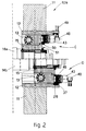
- a rolling mill stand the actuation side 10a of which is shown in Fig.1 while the working side 10b of which is shown in Fig. 2, comprises housings 11 to which are fitted stationary supporting blocks 12, one block per each of two working rolls 14.
- These jacks 38 have the purpose of performing axial displacement of the working rolls 14 during the rolling steps; this axial displacement is carried out during the rolling to displace the working rolls 14 in relation to each other and thus to change the relative working surfaces involved in the rolling action and thereby to make possible a more even distribution of the wear on the surfaces of the rolls 14.
- the working rolls 14 are installed on relative chocks 15, which during installation are secured axially to the relative sliding blocks 13 so as to follow those sliding blocks 13 in the axial movement imparted thereto by the jacks 38.
- the rolling mill stand includes a centralised system to lubricate the bearings of the working rolls 14 by means of female feeder connectors 17 which are included terminally on the front of the chocks 15 and which are connected to mating male connectors 22 on the machine (Fig.5).
- the chocks 15 include a first terminal frontal plate 16, which is fitted to the relative chock 15 by means of a pair of pins 18 provided with footstep bearings 19 and thrust springs 20.
- the footstep bearings 19 and thrust springs 20 have the purpose of compensating any small misalignments which might occur during installation.
- the first plate 16 includes a pair of insertion and alignment pins 21 and a pair of the female connectors 17 to feed the lubricating fluid.
- the male connectors 22 are connected to the centralised lubrication system by means of feeder hoses 23 and hydraulic conduits 36.
- the male connectors 22 are fitted to a second plate 24, which has an overturned-T shaped section and can move transversely to the axis of the working rolls 14 within a groove 25, which has a mating shape and is machined in the sliding block 13.
- the second overturned-T shaped plate 24 is provided with a pair of holes 35, which are shown with their axes drawn with lines of dashes (Fig.5) and within which the insertion and alignment pins 21 are inserted and clamped pneumatically during installation of the chocks 15.
- microswitches are included (but not shown) and give warning of the clamping and release of the insertion and alignment pins 21.
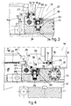
- the clamping/release device on the actuation side 10a consists substantially of a lever 27 that can oscillate about a pivot 29 owing to the action of a hydraulic cylinder/piston actuator 28.
- the oscillatory lever 27 is lodged in a hollow 33 machined in the sliding block 13 and is equipped in this case with a tooth 30 on one side and is conformed as a hook 32 on its other side.
- the lever 27 has a first closed clamping position (Fig. 3) to clamp the chock 15 and a second open position (Fig. 4) to release the chock 15. In its first closed clamping position the lever 27 secures the chock 15 axially to the relative sliding block 13.
- the tooth 30 of the lever 27 in its first closed clamping position is located within a hollow 31 contained in a longitudinally defined position in the chock 15.
- the axial constraint provided by the tooth 30 enables the chock 15 to follow the relative sliding block 13 in the axial movement imparted to the latter 13 by the jack 38.
- the female connectors 17 are connected to the relative male connectors 22, which in turn can follow the axial movement of the chocks 15 since the overturned-T shaped second plate 24 too is secured axially to the sliding block 13 owing to the presence of the insertion and alignment pins 21 within the holes 35.
- the male connectors 22 can follow the chocks 15 in the movement of the latter 15 transversely to the lengthwise axis of the sliding blocks 13 inasmuch as the overturned-T shaped second plate 24 can slide transversely within the groove 25 contained in the sliding blocks 13.
- This hydraulic cylinder/piston actuator 28 has the end 34 of its rod spherical, and a block 39 advantageously made of bronze and inserted into a groove 40 in the lever 27 is associated with that end 34.
- Actuation of the hydraulic cylinder/piston actuator 28 causes rotation of the lever 27 about its pivot 29, sliding of the block 39 in the groove 40 and partial rotation of the block 39 itself about the end 34 of the rod.
- hook-shaped end 32 acts on the ends of the base of the overturned-T shaped second plate 24, and those ends leave the groove 25 in the sliding block 13 (Fig.4).
- This tooth 30 secures the chock 15 axially to the sliding block 13 and at the same time frees from constraint the male connectors 22, which can thus follow the axial and/or transverse movements of the chocks 15.
- a coordinated axial clamping device is included on the working side 10b and makes possible, in a first position, the securing of the chock 15 axially to the relative sliding block 13 and, in a second position, the release of the chock 15 from the sliding block 13, at the same time clamping the sliding block 13 to the relative stationary block 12.
- Fig.2 shows a situation in which the chock 15 of the upper roll 14a is clamped axially to the relative sliding block 13 and is therefore in the working step.
- the chock 15 of the lower roll 14b is axially free from the relative sliding block 13 and can be withdrawn for replacement of the roll 14 for instance, while the relative sliding block 13 is secured axially to the stationary block 12.
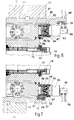
- cylindrical end 41 of the sliding block 13 contains a space for lodgement of a grooved shaft 42 of an actuator 43, which in this instance is of a hydraulic type.
- This cylindrical end 41 moreover, includes holes for fixture of a flange 44 by means of screws 52; this flange 44 acts as an abutment on a bearing 45 of a rotary sleeve 46 and clamps the rotary sleeve 46 axially in relation to the sliding block 13.
- the rotary sleeve 46 is solidly fixed by means of screws 47 to the hydraulic actuator 43, which can rotate since it is provided with a rotary joint 48 associated with hydraulic feeder conduits 49.
- the rotary sleeve 46 comprises in a circumferential position defined at an angle a first clamping projection 50 jutting out circumferentially and a second clamping projection 37 jutting out circumferentially.
- the rotary sleeve 46 includes only one clamping projection.
- clamping projections 50 and 37 are offset from each other at an angle by an angle less than 180° for obvious reasons of non-contact; this angle is advantageously 90°.
- the rotary sleeve 46 has a first position defined at an angle, in which it clamps the chock 15 axially to the relative sliding block 13 for the normal working of the rolling cycle (Fig.6); in this position the sliding block 13 is released from the stationary block 12.
- the rotary sleeve 46 has also a second position, in which it secures the sliding block 13 axially to the relative stationary block 12 and at the same time releases the chock 15, which can be withdrawn axially from the relative sliding block 13.
- the two clamping positions of the rotary sleeve 46 are coordinated with as many longitudinally defined positions of the sliding block 13, one of these positions in relation to the chock 15 and the other position in relation to the stationary block 12.
- this second position of the rotary sleeve 46 obtained by rotation of the hydraulic actuator 43 releases the chock 15 axially from the relative sliding block 13 and at the same time secures the sliding block 13 to the relative stationary block 12.
- the stationary block 12 includes a grooved insertion hollow 26 with which the second clamping projection 37 cooperates in the second position of the rotary sleeve 46 (Fig.7).
Landscapes
- Engineering & Computer Science (AREA)
- Mechanical Engineering (AREA)
- Jigs For Machine Tools (AREA)
- Forklifts And Lifting Vehicles (AREA)
- Coating With Molten Metal (AREA)
- Treatment Of Fiber Materials (AREA)
- Rolling Contact Bearings (AREA)
- Machine Tool Units (AREA)
Claims (6)
- Vorrichtung zum axialen Festspannen/Lösen von Zapfenlagern (15) von Arbeitswalzen (14) an einem Walzgestell, das eine Betätigungsseite (10a) und eine Bearbeitungsseite (10b) aufweist, wobei stationären Blöcken (12) zugeordnete stationäre Gehäuse (11) an den Seiten vorhanden sind, wobei jedem der stationären Blöcke (12) ein jeweiliger Gleitbewegungsblock (13) zugeordnet ist, der in einer Richtung axial zu den Arbeitswalzen (14) positioniert ist, wobei jeder Gleitbewegungsblock (13) eine Lagerung für ein Zapfenlager (15) bildet, wobei die Lager der Arbeitswalzen (14) durch ein zentralisiertes Luft-Öl-System geschmiert werden, das einen ersten Teil von Verbindern (22), die an der Maschine liegen und an einer Trägereinrichtung (24) befestigt sind, und einen zweiten Teil von Verbindern (17) aufweist, die an der Vorderseite des jeweiligen Zapfenlagers (15) vorhanden sind, dadurch gekennzeichnet, dass den Gleitbewegungsblöcken (13) auf der Betätigungsseite (10a) eine schwingende Einrichtung (27) zugeordnet ist, die die Gleitbewegungsblöcke (13) an/von den jeweiligen Zapfenlagern (15) festspannt/löst, wobei sich diese schwingende Festspann/Löse-Einrichtung (27) von einer zweiten Stellung des Lösens des Zapfenlagers (15) vom jeweiligen Gleitbewegungsblock (13) in eine erste Festspannstellung bewegen kann, wobei diese Festspann/Löse-Einrichtung (27) in ihrer zweiten Lösestellung auf diejenige Einrichtung (24) einwirkt, die den ersten Teil der Verbinder (22) trägt, um den ersten Teil der Verbinder (22) an einer vorbestimmten Stellung festzuspannen, die axial mit der Position des zweiten Teils der Verbinder (17) koordiniert ist.
- Vorrichtung nach Anspruch 1, bei der die Festspann/Löse-Einrichtung (17) in ihrer ersten Festspannposition mit einer im Zapfenlager (15) enthaltenen Queraussparung (31) zusammenwirkt.
- Vorrichtung nach Anspruch, bei der auf der Bearbeitungsseite (10b) eine sich drehende Büchse (46) endseitigt an mindestens einem Ende (41) des Gleitbewegungsblocks (13) vorhanden ist, deren Achse im Wesentlichen parallel zur Achse der jeweiligen Walze (14) verläuft, wobei sie unter einem Winkel positioniert werden kann und wobei diese sich drehende Büchse (46) mindestens einen ersten Festspannvorsprung (50), der in Umfangsrichtung unter einem festgelegten Winkel positioniert ist und der mindestens eine erste Winkelstellung aufweist, in der er mit einer Anschlagseinrichtung (51) oder einer Aussparungseinrichtung, die auf der Seite des Zapfenlagers (15) liegt, zusammenwirkt, und mindestens eine zweite Winkelstellung aufweist, in der sie mit einer Anschlagseinrichtung oder mit einer Aussparungseinrichtung (26) zusammenwirkt, die seitens des stationären Blocks (12) vorliegt.
- Vorrichtung nach Anspruch 3, bei der die Anschlagseinrichtung (51) oder die Aussparungseinrichtung (26) dem ersten Festspannvorsprung (50) in einer definierten Längsstellung des Gleitbewegungsblocks (13) zuordenbar ist.
- Vorrichtung nach Anspruch 3 oder 4, bei der die sich drehende Büchse (46) mindestens einen zweiten Festspannvorsprung (37) aufweist, der auf dem Umfang unter einem Winkel in Bezug auf den ersten Festspannvorsprung (50) positioniert ist.
- Vorrichtung nach Anspruch 3, 4 oder 5, bei der die sich drehende Büchse (46) einem Winkelstellglied (43) zugeordnet ist.
Applications Claiming Priority (5)
| Application Number | Priority Date | Filing Date | Title |
|---|---|---|---|
| ITUD930238A IT1262241B (it) | 1993-11-29 | 1993-11-29 | Dispositivo di bloccaggio/sbloccaggio assiale delle guarniture dei cilindri in una gabbia di laminazione |
| ITUD930237A IT1262240B (it) | 1993-11-29 | 1993-11-29 | Dispositivo di bloccaggio/sbloccaggio assiale delle guarniture in una gabbia di laminazione |
| ITUD930237 | 1993-11-29 | ||
| ITUS930237 | 1993-11-29 | ||
| ITUD930238 | 1993-11-29 |
Publications (2)
| Publication Number | Publication Date |
|---|---|
| EP0655284A1 EP0655284A1 (de) | 1995-05-31 |
| EP0655284B1 true EP0655284B1 (de) | 1998-01-21 |
Family
ID=26332505
Family Applications (1)
| Application Number | Title | Priority Date | Filing Date |
|---|---|---|---|
| EP94118184A Expired - Lifetime EP0655284B1 (de) | 1993-11-29 | 1994-11-18 | Vorrichtung zum axialen Spannen/Lösen der Einbaustücke der Walzen in einem Walzgerüst |
Country Status (5)
| Country | Link |
|---|---|
| US (1) | US5596898A (de) |
| EP (1) | EP0655284B1 (de) |
| AT (1) | ATE162436T1 (de) |
| DE (1) | DE69408103T2 (de) |
| ES (1) | ES2111235T3 (de) |
Families Citing this family (10)
| Publication number | Priority date | Publication date | Assignee | Title |
|---|---|---|---|---|
| IT1288878B1 (it) * | 1996-04-19 | 1998-09-25 | Danieli Off Mecc | Dispositivo di movimentazione cilindri in una gabbia di laminazione a quarto per lamiere e/o larghi piatti |
| US6041636A (en) * | 1998-02-20 | 2000-03-28 | T. Sendzimir, Inc. | Side supported 6-high rolling mill |
| US5970771A (en) * | 1998-07-10 | 1999-10-26 | Danieli United | Continuous spiral motion system for rolling mills |
| US6250120B1 (en) | 2000-06-27 | 2001-06-26 | Morgan Construction Company | Apparatus for rotatably supporting the neck of a roll in a rolling mill |
| IT1315121B1 (it) * | 2000-09-25 | 2003-02-03 | Danieli Off Mecc | Dispositivo per assorbire i carichi assiali generati sui cilindri diuna gabbia di laminazione |
| DE10334727A1 (de) * | 2003-07-30 | 2005-02-24 | Sms Demag Ag | Walzvorrichtung |
| CN103949477B (zh) * | 2014-04-25 | 2015-12-23 | 无锡市桥联冶金机械有限公司 | 轧机换辊装置 |
| CN105834221B (zh) * | 2016-05-13 | 2017-08-25 | 中冶华天工程技术有限公司 | 卡盘式防轴窜装置 |
| CN111607928A (zh) * | 2020-06-03 | 2020-09-01 | 金溪县金三龙服饰有限公司 | 一种透气服装面料热定型装置中压辊与机架的连接机构 |
| CN116351884B (zh) * | 2023-03-10 | 2024-07-02 | 中国机械总院集团北京机电研究所有限公司 | 轧辊夹紧机构及楔横轧机 |
Family Cites Families (10)
| Publication number | Priority date | Publication date | Assignee | Title |
|---|---|---|---|---|
| SU806182A1 (ru) * | 1975-07-25 | 1981-02-28 | Предприятие П/Я А-7697 | Узел валков прокатной клети |
| JPH0753285B2 (ja) * | 1984-03-30 | 1995-06-07 | 株式会社日立製作所 | 作業ロール軸受箱を備えた圧延機 |
| JPS6114008A (ja) * | 1984-06-29 | 1986-01-22 | Yokohama Eirokuitsupu Kk | 配管継手の自動接続方法とその装置 |
| JPS6137307A (ja) * | 1984-07-27 | 1986-02-22 | Hitachi Ltd | 圧延機のロ−ル移動装置 |
| EP0313610B1 (de) * | 1987-05-05 | 1992-07-01 | DAVY McKEE (SHEFFIELD) LIMITED | Walzgerüst |
| DE3720545A1 (de) * | 1987-06-22 | 1989-01-05 | Schloemann Siemag Ag | Vorrichtung zur axialen positionierverschiebung von in staenderfenstern der staender von mehrwalzengeruesten gefuehrten walzenlagertraegern |
| SU1502146A1 (ru) * | 1988-02-29 | 1989-08-23 | Производственное Объединение "Ново-Краматорский Машиностроительный Завод" | Устройство осевого перемещени рабочих валков прокатной клети |
| JPH01266907A (ja) * | 1988-04-15 | 1989-10-24 | Hitachi Ltd | 圧延機のワークロール軸受保持装置 |
| SU1667969A1 (ru) * | 1989-06-02 | 1991-08-07 | Производственное объединение "Новокраматорский машиностроительный завод" | Лини клети прокатного стана |
| DE4034436A1 (de) * | 1990-10-29 | 1992-04-30 | Schloemann Siemag Ag | Walzgeruest mit anordnung zur distanzierten abstuetzung der oberen arbeitswalze |
-
1994
- 1994-11-18 AT AT94118184T patent/ATE162436T1/de not_active IP Right Cessation
- 1994-11-18 EP EP94118184A patent/EP0655284B1/de not_active Expired - Lifetime
- 1994-11-18 ES ES94118184T patent/ES2111235T3/es not_active Expired - Lifetime
- 1994-11-18 DE DE69408103T patent/DE69408103T2/de not_active Expired - Fee Related
- 1994-11-28 US US08/348,219 patent/US5596898A/en not_active Expired - Lifetime
Also Published As
| Publication number | Publication date |
|---|---|
| EP0655284A1 (de) | 1995-05-31 |
| US5596898A (en) | 1997-01-28 |
| ES2111235T3 (es) | 1998-03-01 |
| DE69408103D1 (de) | 1998-02-26 |
| ATE162436T1 (de) | 1998-02-15 |
| DE69408103T2 (de) | 1998-09-03 |
Similar Documents
| Publication | Publication Date | Title |
|---|---|---|
| EP0655284B1 (de) | Vorrichtung zum axialen Spannen/Lösen der Einbaustücke der Walzen in einem Walzgerüst | |
| US6041636A (en) | Side supported 6-high rolling mill | |
| US4003219A (en) | Hydraulically operated retractable spindle | |
| EP0557874B1 (de) | Universalwalzgerüst | |
| US2911804A (en) | Rolling mill coupling | |
| AU708596B2 (en) | Compact rolling block | |
| US3878703A (en) | Rolling mills | |
| CN221063988U (zh) | 一种可偏心径向调整的支撑辊轴承组元 | |
| EP0692321B1 (de) | System zur Montage von Walzringen auf einer Walze | |
| US6217081B1 (en) | Device for coupling and uncoupling the media supply lines at bearing chocks of rolls, particularly back-up rolls, mounted in roll housings | |
| JP3501863B2 (ja) | 自動管継手用配管 | |
| EP0815964B1 (de) | Walzenkreuzvorrichtung für Walzwerk | |
| AU708567B2 (en) | Compact rolling block | |
| US3699791A (en) | Work roll bearing lubrication arrangement | |
| EP0815963B1 (de) | Walzenkreuzvorrichtung für Walzwerk | |
| EP1042083B1 (de) | Biegeblock für ein quartowalzgerüst | |
| US6202464B1 (en) | Universal rolling mill | |
| SU995929A1 (ru) | Нажимное устройство стана холодной прокатки труб | |
| CN120920517A (zh) | 一种快速响应高精度预应力轧机和控制方法 | |
| EP0925853B1 (de) | Druckeinheit für oszillierende Walze | |
| GB2117296A (en) | Cold roll tool changing | |
| Mundt | Double universal rolling mill with integral edging mills | |
| JPH05308A (ja) | 幅可変圧延ロール |
Legal Events
| Date | Code | Title | Description |
|---|---|---|---|
| PUAI | Public reference made under article 153(3) epc to a published international application that has entered the european phase |
Free format text: ORIGINAL CODE: 0009012 |
|
| AK | Designated contracting states |
Kind code of ref document: A1 Designated state(s): AT BE DE ES FR GB IT SE |
|
| 17P | Request for examination filed |
Effective date: 19951031 |
|
| GRAG | Despatch of communication of intention to grant |
Free format text: ORIGINAL CODE: EPIDOS AGRA |
|
| 17Q | First examination report despatched |
Effective date: 19970314 |
|
| GRAH | Despatch of communication of intention to grant a patent |
Free format text: ORIGINAL CODE: EPIDOS IGRA |
|
| GRAH | Despatch of communication of intention to grant a patent |
Free format text: ORIGINAL CODE: EPIDOS IGRA |
|
| GRAA | (expected) grant |
Free format text: ORIGINAL CODE: 0009210 |
|
| ITF | It: translation for a ep patent filed | ||
| AK | Designated contracting states |
Kind code of ref document: B1 Designated state(s): AT BE DE ES FR GB IT SE |
|
| REF | Corresponds to: |
Ref document number: 162436 Country of ref document: AT Date of ref document: 19980215 Kind code of ref document: T |
|
| ET | Fr: translation filed | ||
| REF | Corresponds to: |
Ref document number: 69408103 Country of ref document: DE Date of ref document: 19980226 |
|
| REG | Reference to a national code |
Ref country code: ES Ref legal event code: FG2A Ref document number: 2111235 Country of ref document: ES Kind code of ref document: T3 |
|
| PLBE | No opposition filed within time limit |
Free format text: ORIGINAL CODE: 0009261 |
|
| STAA | Information on the status of an ep patent application or granted ep patent |
Free format text: STATUS: NO OPPOSITION FILED WITHIN TIME LIMIT |
|
| 26N | No opposition filed | ||
| REG | Reference to a national code |
Ref country code: GB Ref legal event code: IF02 |
|
| PGFP | Annual fee paid to national office [announced via postgrant information from national office to epo] |
Ref country code: GB Payment date: 20031029 Year of fee payment: 10 Ref country code: SE Payment date: 20031029 Year of fee payment: 10 |
|
| PGFP | Annual fee paid to national office [announced via postgrant information from national office to epo] |
Ref country code: BE Payment date: 20031031 Year of fee payment: 10 |
|
| PGFP | Annual fee paid to national office [announced via postgrant information from national office to epo] |
Ref country code: ES Payment date: 20031112 Year of fee payment: 10 |
|
| PG25 | Lapsed in a contracting state [announced via postgrant information from national office to epo] |
Ref country code: GB Free format text: LAPSE BECAUSE OF NON-PAYMENT OF DUE FEES Effective date: 20041118 |
|
| PG25 | Lapsed in a contracting state [announced via postgrant information from national office to epo] |
Ref country code: SE Free format text: LAPSE BECAUSE OF NON-PAYMENT OF DUE FEES Effective date: 20041119 Ref country code: ES Free format text: LAPSE BECAUSE OF NON-PAYMENT OF DUE FEES Effective date: 20041119 |
|
| PG25 | Lapsed in a contracting state [announced via postgrant information from national office to epo] |
Ref country code: BE Free format text: LAPSE BECAUSE OF NON-PAYMENT OF DUE FEES Effective date: 20041130 |
|
| BERE | Be: lapsed |
Owner name: *DANIELI & C. OFFICINE MECCANICHE S.P.A. Effective date: 20041130 |
|
| EUG | Se: european patent has lapsed | ||
| GBPC | Gb: european patent ceased through non-payment of renewal fee |
Effective date: 20041118 |
|
| REG | Reference to a national code |
Ref country code: ES Ref legal event code: FD2A Effective date: 20041119 |
|
| BERE | Be: lapsed |
Owner name: *DANIELI & C. OFFICINE MECCANICHE S.P.A. Effective date: 20041130 |
|
| PGFP | Annual fee paid to national office [announced via postgrant information from national office to epo] |
Ref country code: DE Payment date: 20081126 Year of fee payment: 15 |
|
| PGFP | Annual fee paid to national office [announced via postgrant information from national office to epo] |
Ref country code: AT Payment date: 20081023 Year of fee payment: 15 |
|
| PGFP | Annual fee paid to national office [announced via postgrant information from national office to epo] |
Ref country code: IT Payment date: 20081117 Year of fee payment: 15 |
|
| PGFP | Annual fee paid to national office [announced via postgrant information from national office to epo] |
Ref country code: FR Payment date: 20081126 Year of fee payment: 15 |
|
| REG | Reference to a national code |
Ref country code: FR Ref legal event code: ST Effective date: 20100730 |
|
| PG25 | Lapsed in a contracting state [announced via postgrant information from national office to epo] |
Ref country code: AT Free format text: LAPSE BECAUSE OF NON-PAYMENT OF DUE FEES Effective date: 20091118 |
|
| PG25 | Lapsed in a contracting state [announced via postgrant information from national office to epo] |
Ref country code: FR Free format text: LAPSE BECAUSE OF NON-PAYMENT OF DUE FEES Effective date: 20091130 |
|
| PG25 | Lapsed in a contracting state [announced via postgrant information from national office to epo] |
Ref country code: DE Free format text: LAPSE BECAUSE OF NON-PAYMENT OF DUE FEES Effective date: 20100601 |
|
| PG25 | Lapsed in a contracting state [announced via postgrant information from national office to epo] |
Ref country code: IT Free format text: LAPSE BECAUSE OF NON-PAYMENT OF DUE FEES Effective date: 20091118 |