EP0653852B1 - Leitungsungebundene optische Kommunikationssysteme - Google Patents
Leitungsungebundene optische Kommunikationssysteme Download PDFInfo
- Publication number
- EP0653852B1 EP0653852B1 EP94118016A EP94118016A EP0653852B1 EP 0653852 B1 EP0653852 B1 EP 0653852B1 EP 94118016 A EP94118016 A EP 94118016A EP 94118016 A EP94118016 A EP 94118016A EP 0653852 B1 EP0653852 B1 EP 0653852B1
- Authority
- EP
- European Patent Office
- Prior art keywords
- light
- signal
- optical
- pilot signal
- expanse
- Prior art date
- Legal status (The legal status is an assumption and is not a legal conclusion. Google has not performed a legal analysis and makes no representation as to the accuracy of the status listed.)
- Expired - Lifetime
Links
Images

Classifications
-
- H—ELECTRICITY
- H04—ELECTRIC COMMUNICATION TECHNIQUE
- H04B—TRANSMISSION
- H04B10/00—Transmission systems employing electromagnetic waves other than radio-waves, e.g. infrared, visible or ultraviolet light, or employing corpuscular radiation, e.g. quantum communication
- H04B10/11—Arrangements specific to free-space transmission, i.e. transmission through air or vacuum
- H04B10/112—Line-of-sight transmission over an extended range
- H04B10/1123—Bidirectional transmission
- H04B10/1125—Bidirectional transmission using a single common optical path
Definitions
- This invention relates to an optical space communication apparatus for converting an optical signal modulated by a transmission signal into a beam of light and propagating the beam of light through the atmosphere to thereby effect communication between remote points.
- optical space communication using free space as a transmission path has an advantage that it abounds in portability as compared with wire communication as by optical fiber and its communication paths can be simply set up.
- the correction i.e., auto tracking, of the angle of a beam of light in the direction of emergence thereof is effected so that optical signals may not come off the apparatus.
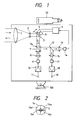
- FIG. 1 of the accompanying drawings shows the construction of an example of the prior art which is an optical space communication apparatus having the tracking function.
- a lens 1 for transmission/reception there are disposed a lens 2 and a movable mirror 3, and two actuators 4 and 5 for changing the angle of the movable mirror 3 are mounted on the movable mirror 3.
- These actuators 4 and 5 are adapted to be driven by the output of a tracking control circuit 6.
- a polarizing beam splitter 7 transmitting therethrough a polarized plane component parallel to the plane of the drawing sheet and reflecting a polarized plane component perpendicular to the plane of the drawing sheet by a cemented surface 7a, a lens 8, and a light emitting element 9 comprising a semiconductor laser or the like, and the outputs of an amplifier 10 and a transmission signal input end 11 are successively connected to the light emitting element 9.
- a beam dividing mirror 12 On the optical path in the direction of reflection of the polarizing beam splitter 7, there are disposed a beam dividing mirror 12, a lens 13 and a light receiving element 14 having four light receiving elements 14a - 14d as shown in Figure 2 of the accompanying drawings.
- the output of the light receiving element 14 is connected to the tracking control circuit 6.
- a lens 15 and a light receiving element 17 comprising an avalanche photodiode, a PIN photodiode or the like, and the outputs of an amplifier 18 and a reception signal output end 19 are successively connected to the light receiving element 17.
- a collimation scope 20 made substantially parallel to the optical axis of the lens 1 and for an operator to visually confirm a partner apparatus.
- a transmission signal is inputted from the transmission signal input end 11, it is amplified by the amplifier 10, and thereafter is outputted to the light emitting element 9.
- the light emitting element 9 intensity-modulates oscillated light in accordance with the input signal and converts it into an optical signal.
- the oscillated light from the light emitting element 9 passes through the lens 8 to the polarizing beam splitter 7, but this light is polarized in parallelism to the plane of the drawing sheet and therefore is intactly transmitted through the polarizing beam splitter 7, and is reflected leftwardly by the movable mirror 3, and is converted into a beam of light via the lenses 2 and 1, and emerges toward the partner apparatus.
- the beam of light from the partner apparatus enters the lens 1 from left, is downwardly reflected by the movable mirror 3 and passes to the polarizing beam splitter 7. Since this beam of light is polarized in a direction perpendicular to the plane of the drawing sheet, it is rightwardly reflected by the cemented surface 7a of the polarizing beam splitter 7, and is divided into two directions by the beam dividing mirror 12.
- the beam of light reflected by the beam dividing mirror 12 is received by the light receiving element 17 and is converted into an electrical signal thereby, whereafter the electrical signal is amplified to a suitable level by the amplifier 18 and is outputted from the reception signal output end 19.
- the beam of light transmitted through the beam dividing mirror 12 is condensed by the lens 13, and is received as a spot image S comprising a small circle as shown in Figure 2 by the light receiving element 14.
- the outputs of the four light receiving elements 14a - 14d are compared with one another to thereby find the position of the spot image S, which is outputted as a position signal to the tracking control circuit 6.
- the tracking control circuit 6 calculates the angle the beam of light from the partner apparatus forms with respect to the optical path of the host apparatus, and makes a driving signal for the actuators 4 and 5.
- the actuators 4 and 5 adjust the angle of the movable mirror 3 so that the spot image S may be received by the center of the light receiving element 14.
- the position of the light emitting element 9 is also adjusted and thus, the optical paths of the emergent beam of light and the incident beam of light coincide with each other, that is, the beam of light is accurately transmitted toward the partner apparatus.
- the apparatus is inclined and the optical path of the received light deviates and the position of the spot image S on the light receiving element 14 deviates from the center, the movable mirror 3 is immediately moved and the optical path for the incidence of the beam of light is sequentially modified so that the spot image S may be received by the center of the light receiving element 14, thereby preventing the incident beam of light from deviating from the apparatus.
- the above-described tracking function will not operate unless the beam of light from the partner apparatus arrives at a receivable level and the spot image S is received by a portion of the light receiving element 14. Accordingly, in the initial adjustment during the installation of the apparatus, the operator fixes the movable mirror 3 at an initial position near the midpoint, and manually effects the adjustment of the angle of a base 100 to thereby effect the adjustment of the direction of the entire apparatus while observing the partner apparatus by means of the collimation scope 20.
- the beam of light is used in the state of a parallel beam of light.
- the angle of expanse of the beam of light on the transmitting side is set to the order of 0.2° for a transmission distance of 500 m, and is set to a small angle of expanse of the order of 0.06° for a transmission distance of 2,000 m.
- whether the light receiving element 14 is receiving the spot image S can be confirmed by monitoring the light reception signal of the light receiving element 14, but whether the beam of light from the host apparatus is being received by the light receiving element of the partner apparatus cannot be confirmed from the host apparatus side.
- a value including the error of the angle of emergence of the beam of light and the visual confirmation error of the collimation scope 20 be suppressed to a small level.
- both terminals point to predetermined positions within the opposite terminal's uncertainty area, wherein one of the terminals emits a wide beam illuminating the entire uncertainty area of the other terminal, which emits a beam of small aperture.
- the widened beam is zoomed to a small divergence.
- main and pilot signals are used, wherein the pilot signal is used for the acquisition sequence.
- Fig. 1 shows the construction of an example of the prior art.
- Fig. 2 is a front view of a photodiode.
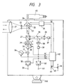
- Figs. 3 and 4 show the construction of a first embodiment of the optical space communication apparatus of the present invention.
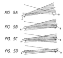
- Figs. 5A to 5D illustrate a variation in a beam of light resulting from the adjustment of the direction of emergence.
- a lens 22 and a movable mirror 23 are disposed on the optical path behind a lens 21 which is the entrance and exit of the apparatus.
- Actuators 24 and 25 are mounted on the movable mirror 23, and the output of a tracking control circuit 26 is connected to these actuators.
- a polarizing beam splitter 27 transmitting therethrough a polarized wave parallel to the plane of the drawing sheet and reflecting a polarized wave orthogonal to the plane of the drawing sheet, a collimator lens 29 movable along the optical path by driving means 28, and a light emitting element 30 comprising a semiconductor laser or the like are successively arranged on the optical path in the direction of reflection of the movable mirror 23, the outputs of a wave combiner 31, an amplifier 32 and a transmission signal input end 33 are successively connected to the light emitting element 30, and the output of a pilot signal oscillator 34 is connected to the wave combiner 31.
- a beam dividing mirror 35, a lens 36 and a PIN photodiode 37 having four light receiving elements similarly to the light receiving element 14 in the example of the prior art are disposed on the optical path in the direction of reflection of the polarizing beam splitter 27, and the output of the PIN photodiode 37 is connected to the tracking control circuit 26.
- a lens 38 and a light receiving element 39 are disposed on the optical path in the direction of reflection of the beam dividing mirror 35, and the output of the light receiving element 39 is connected to an amplifier 40 and a reception signal output end 41.
- a system control circuit 42 is provided to control the entire apparatus, the output of the system control circuit 42 is connected to the tracking control circuit 26, the driving means 28, the amplifier 32 and the pilot signal oscillator 34, and a tracking start switch 43 and the output of a distance setting device 44 for setting the transmission distance are connected to the system control circuit 42. Also, a collimation scope 45 is provided outside the apparatus. A base 200 for manually effecting the adjustment of the angle of the entire apparatus is also provided outside the apparatus.
- the wave combiner 31 In case of transmission, information is inputted as a main signal from the transmission signal input end 33 and is amplified by the amplifier 32, and thereafter is outputted to the wave combiner 31.
- the wave combiner 31 superposes the main signal and a pilot signal for tracking from the pilot signal oscillator 34 one upon the other, and thereafter outputs them to the light emitting element 30.
- the semiconductor laser in the light emitting element 30 modulates oscillated light on the basis of an input signal and converts it into an optical signal.
- the oscillated light from the light emitting element 30 is polarized in parallelism to the plane of the drawing sheet, passes through the polarizing beam splitter 27, is reflected by the movable mirror 23, is converted into a beam of light via the lenses 22 and 21 and emerges into space.
- the transmitted optical signal comprises a main signal including information and a pilot signal for tracking.
- the main signal is a high band signal including also a high frequency component
- the pilot signal is a narrow band signal comprising a low frequency component which does not overlap the frequency band of the main signal. Accordingly, the pilot signal can be received in a narrow band and therefore, a high S/N ratio is obtained even at a low level and thus, during ordinary communication, the level distribution ratio of the pilot signal is set lower than that of the main signal in order to make the influence imparted to the main signal small.
- such an optical signal comprising the main signal including information and the pilot signal for tracking enters from the lens 21 and is condensed, and is made into parallel light by the lens 22 and the parallel light is reflected by the movable mirror 23. Thereafter, this light, which is a polarized wave orthogonal to the plane of the drawing sheet, is reflected by the polarizing beam splitter 27 and is divided into two directions by the beam dividing mirror 35.
- the beam of light transmitted through the beam dividing mirror 35 passes through the lens 36 and is received as a spot image S comprising a small circle by the PIN photodiode 37.
- the beam of light reflected by the beam dividing mirror 35 passes through the lens 38 and is received by the light receiving element 39.
- the light receiving element 39 which is high in response speed, receives the main signal of a high frequency band and converts it into an electrical signal. This signal is amplified by the amplifier 40, and thereafter is outputted from the reception signal output end 41.
- the PIN photodiode 37 which is low in response speed, receives the pilot signal of a low frequency band of the optical signal and converts it into an electrical signal, and outputs it to the tracking control circuit 26. On the basis of this signal, the tracking control circuit 26 calculates the position of the spot image S on the PIN photodiode 37, and monitors the direction of reception of the optical signal.
- Figs. 5A to 5D assuming that two apparatuses for effecting communication therebetween are apparatus A and apparatus B, the users of the two apparatuses A and B render the apparatuses into a transmission state (Fig. 5A), and manually effect the adjustment of the directions of the two apparatus while looking into the collimation scope 45 and observing the incident beam of light (Fig. 5A ⁇ Fig. 5B).
- the system control circuit 42 outputs a command signal FL to the driving means 28.
- the collimator lens 29 is moved along the optical path by the driving means 28, thereby making the angle of expanse of the beam of light great as shown in Fig. 5A.
- the beam of light from the host apparatus can be caused to enter the other apparatus by a simple operation.
- the transmitted optical signal is attenuated by the beam of light being expanded and therefore, the system control circuit 42 outputs a command signal PL to the pilot signal oscillator 34 in synchronism with outputting the command signal FL to the driving means 28.
- the pilot signal oscillator 34 outputs to the wave combiner 31 a pilot signal of a higher level than during ordinary communication to ensure the pilot signal to be reliably received by the partner apparatus.
- the system control circuit 42 may be designed to output a command signal SL to the amplifier 32 to make the level of the main signal lower than during communication. As a result, in the amplifier 32, the level of the main signal becomes nearly zero. In this case, the level of the pilot signal may be increased correspondingly to the decrease in the level of the main signal.
- the system control circuit 42 of the apparatus A confirms that the reception level of the pilot signal from the apparatus B is sufficient, and connects the tracking start switch 43 to thereby input the start of tracking to the system control circuit 42.
- the system control circuit outputs a command signal TR to the tracking control circuit 26.
- the tracking control circuit 26 compares the reception signals from the four light receiving elements of the PIN photodiode 37 with one another to thereby find the position of the spot image S and make a driving signal for the actuators 24 and 25.
- the actuators 24 and 25 adjust the angle of the movable mirror 23 so that the spot image S may be received by the center of the PIN photodiode 37, and the optical path of the beam of light from the apparatus A and the optical path of the beam of light from the apparatus B are made coincident with each other as shown in Fig. 5C.
- the system control circuit 42 When in the apparatus A, the direction of emergence of the beam of light is determined, the system control circuit 42 outputs the command signal FL to the driving means 28 and also outputs the command signal PL to the pilot signal oscillator 34.
- the driving means 28 moves the collimator lens 29 to thereby make the angle of expanse of the beam of light smaller as shown in Fig. 5D.
- the pilot signal oscillator 34 reduces the output level of the signal to the wave combiner 31, and drops the level of the pilot signal to the level during ordinary communication.
- the system control circuit 42 controls the amplifier 32 by a command signal SL to thereby amplify the level of the input signal from the transmission signal input end 33 to a communicable level.
- the tracking control circuit 26 sequentially monitors the position of the spot image S on the PIN photodiode 37, adjusts the movable mirror 23 by the actuators 24 and 25 and effects the tracking of the transmission/reception beam of light.
- the above-described tracking is particularly effective when the communication distance is long.
- the adjustment of the direction of emergence in the apparatus B is started after the termination of the adjustment of the direction of emergence in the apparatus A, but in the state of Fig. 5B, the tracking start switch 43 may be connected in the apparatus A and apparatus B at a time to thereby effect the adjustment of the directions of emergence, the angles of expanse and the output levels of the beams of light.
- the system control circuit 42 sets the angle of expanse of the beam of light and the amplification factor of the level of the pilot signal in conformity with the transmission distance. For example, when the adjustment of the direction of emergence of the beam of light is to be made, the beam diameter at the receiving point is set to the order of 10 m. In such case, for a transmission distance of 500 m, the angle of expanse of the beam of light on the transmission side is expanded to the order of 1°, and for a transmission distance of 2,000 m, this angle is expanded to the order of 0.3°.
- the beam diameter at the receiving point is set to the order of 2 m.
- the angle of expanse of the beam of light on the transmission side is narrowed to the order of 0.2°, and for a transmission distance of 2,000 m, this angle is narrowed to the order of 0.06°.
- the distance setting device 44 is comprised of a potentiometer or the like provided with distance divisions, but alternatively may be comprised of a digital switch.
- the pilot signal is superposed upon the main signal to detect the direction of incidence of the beam of light, but it is also possible to use the main signal as a signal for detecting the direction of incidence of the beam of light.
- the PIN photodiode 37 is designed to receive the DC component of the main signal. In this method, the detection accuracy of the PIN photodiode 37 is reduced, but there is an advantage that the mechanism can be simplified. Further, instead of the PIN photodiode 37, use may be made of only an element of high response speed which can also detect the high frequency component of the main signal. In such case, the beam dividing mirror 35 and the light receiving element 39 may be eliminated, and the main signal can be received by said element so that tracking and communication may be effected.
- the pilot signal and the main signal are superposed one upon the other by the difference in frequency band, but use can also be made of a method such as wavelength multiplexing, time division multiplexing or code multiplexing.
- the pilot signal is converted into an optical signal by a light emitting element oscillating a light emission wavelength differing from the main signal, whereafter the optical signal is combined with an optical signal derived from the main signal and the combined optical signal is transmitted as a beam of light.
- the pilot signal and the main signal are divided in the beam dividing mirror 35 by wavelength.
- the pilot signal is transmitted through the beam dividing mirror 35 and is received by the PIN photodiode 37, and the main signal is reflected by the beam dividing mirror 35 and is received by the light receiving element 39.
- two light emitting elements differing in wavelength from each other are used and therefore the construction becomes complicated, but the main signal will not be affected even if the output level of the pilot signal is made great.
- the optical space communication apparatus is designed to detect an optical signal of a great angle of expanse and a great output level for adjusting the direction of emergence of the beam of light, and correct the direction of emergence of the beam of light and therefore, even during long distance communication, the adjustment of the direction of the apparatus can be made easily and highly accurately. Also, the manufacturing accuracy of the optical members is alleviated and thus, lower costs can be achieved.
Landscapes
- Physics & Mathematics (AREA)
- Electromagnetism (AREA)
- Engineering & Computer Science (AREA)
- Computer Networks & Wireless Communication (AREA)
- Signal Processing (AREA)
- Optical Communication System (AREA)
Claims (4)
- Optische, leitungsungebundene Kommunikationsvorrichtung zum Übertragen eines Lichtstrahlbündels durch den freien Raum zwecks Kommunikation, umfassend:dadurch gekennzeichnet, daß die Vorrichtung außerdem aufweist:eine Sendeeinrichtung (30, 27, 23, 22, 21) zum Senden eines Hauptsignals und eines Pilotsignals, die in Lichtstrahlbündel umgewandelt wurden;eine Aufweitwinkel-Änderungseinrichtung (29) zum Variieren der Aufweitwinkel der Lichtstrahlbündel, in welche das Hauptsignal und das Pilotsignal umgewandelt wurden;eine Steuereinrichtung (42) zum Steuern der Aufweitwinkel-Änderungseinrichtung (29); undeine Empfangseinrichtung (39) zum Empfangen eines in ein Lichtstrahlbündel umgewandelten optischen Signals;
eine Pegeländerungseinrichtung (42) zum Variieren der Ausgangspegel des Hauptsignals und des Pilotsignals, wobei die Steuereinrichtung (42) die Pegeländerungseinrichtung (42) in der Weise steuert, daß der Ausgangspegel des Pilotsignals angehoben und der Ausgangspegel des Hauptsignals abgesenkt wird, wenn die Aufweitwinkel der Strahlbündel vergrößert werden. - Vorrichtung nach Anspruch 1, bei der die Steuereinrichtung (42) den Ausgangspegel des Pilotsignals klein macht, wenn der Ausgangspegel des Hauptsignals groß gemacht wird, und den Ausgangspegel des Pilotsignals groß macht, wenn der Ausgangspegel des Hauptsignals klein gemacht wird.
- Vorrichtung nach Anspruch 1, bei der das Pilotsignal sich im Frequenzband oder der Wellenlänge von dem Hauptsignal unterscheidet.
- Verfahren zum Einjustieren der Austrittsrichtung eines Lichtstrahlbündels in einem optischen, leitungsungebundenen Kommunikationssystem zum Übertragen eines Lichtstrahlbündels durch den freien Raum zwecks Kommunikation, umfassend die Schritte:dadurch gekennzeichnet, daßSenden eines ersten optischen Signals, welches in ein erstes Lichtstrahlbündel umgewandelt wurde, aus einer ersten optischen, leitungsungebundenen Kommunikationsvorrichtung in eine zweite optische, leitungsungebundene Kommunikationsvorrichtung;Ändern des Aufweitwinkels des ersten Lichtstrahlbündels, in welches das erste optische Signal umgewandelt wurde;Senden eines zweiten optischen Signals, welches in ein zweites Lichtstrahlbündel umgewandelt wurde, von der zweiten optischen, leitungsungebundenen Kommunikationsvorrichtung zu der ersten optischen, leitungsungebundenen Kommunikationsvorrichtung;Ändern des Aufweitwinkels des zweiten Lichtstrahlbündels, in welches das zweite optische Signal umgewandelt wurde; undEinjustieren der Austrittsrichtungen des ersten Lichtstrahlbündels und des zweiten Lichtstrahlbündels,
das erste und das zweite optische Signal jeweils ein Hauptsignal und ein Pilotsignal aufweisen, die in optische Signale umgewandelt wurden, wobei der Ausgangspegel jedes Pilotsignals angehoben und der Ausgangspegel des entsprechenden Hauptsignals abgesenkt wird, wenn die Aufweitwinkel der betreffenden Strahlbündel vergrößert werden.
Applications Claiming Priority (3)
| Application Number | Priority Date | Filing Date | Title |
|---|---|---|---|
| JP309734/93 | 1993-11-16 | ||
| JP30973493A JP3302141B2 (ja) | 1993-11-16 | 1993-11-16 | 光空間通信方法 |
| JP30973493 | 1993-11-16 |
Publications (2)
| Publication Number | Publication Date |
|---|---|
| EP0653852A1 EP0653852A1 (de) | 1995-05-17 |
| EP0653852B1 true EP0653852B1 (de) | 2002-03-20 |
Family
ID=17996659
Family Applications (1)
| Application Number | Title | Priority Date | Filing Date |
|---|---|---|---|
| EP94118016A Expired - Lifetime EP0653852B1 (de) | 1993-11-16 | 1994-11-15 | Leitungsungebundene optische Kommunikationssysteme |
Country Status (4)
| Country | Link |
|---|---|
| US (1) | US5594580A (de) |
| EP (1) | EP0653852B1 (de) |
| JP (1) | JP3302141B2 (de) |
| DE (1) | DE69430167T2 (de) |
Families Citing this family (62)
| Publication number | Priority date | Publication date | Assignee | Title |
|---|---|---|---|---|
| US5801866A (en) * | 1992-08-27 | 1998-09-01 | Trex Communications Corporation | Laser communication device |
| JP3323651B2 (ja) * | 1993-09-24 | 2002-09-09 | キヤノン株式会社 | 光空間通信装置 |
| JP3311187B2 (ja) * | 1995-01-26 | 2002-08-05 | キヤノン株式会社 | 双方向光空間伝送装置 |
| JP3311197B2 (ja) * | 1995-03-22 | 2002-08-05 | キヤノン株式会社 | 双方向光空間伝送装置 |
| US6931183B2 (en) | 1996-03-29 | 2005-08-16 | Dominion Lasercom, Inc. | Hybrid electro-optic cable for free space laser antennas |
| US6348986B1 (en) | 1996-03-29 | 2002-02-19 | Dominion Lasercom. Inc. | Wireless fiber-coupled telecommunication systems based on atmospheric transmission of laser signals |
| JP3859335B2 (ja) * | 1996-12-17 | 2006-12-20 | Nec東芝スペースシステム株式会社 | 光通信装置および光通信システム |
| US5953146A (en) * | 1997-01-30 | 1999-09-14 | At&T Corp. | Method and apparatus for tracking alignment in wireless optical communications |
| US6154297A (en) * | 1997-03-19 | 2000-11-28 | At&T Corp | Optical transceiver using common optical path for transmission and reception |
| DE19715636A1 (de) * | 1997-04-15 | 1998-10-22 | Renfer Robert O | Vorrichtung zur drahtlosen optischen Übertragung |
| JPH10301056A (ja) * | 1997-04-30 | 1998-11-13 | Canon Inc | 投・受光装置 |
| US6016212A (en) * | 1997-04-30 | 2000-01-18 | At&T Corp | Optical receiver and demultiplexer for free-space wavelength division multiplexing communications systems |
| AU9300798A (en) * | 1997-09-02 | 1999-03-22 | Trex Communications Corporation | Laser communication transceiver |
| JPH11122179A (ja) * | 1997-10-09 | 1999-04-30 | Seiko Epson Corp | 空間光伝送装置及び空間光伝送方法 |
| JPH11136190A (ja) * | 1997-10-24 | 1999-05-21 | Canon Inc | 光空間通信装置 |
| DE19756935C2 (de) * | 1997-12-20 | 2001-12-06 | Deutsch Zentr Luft & Raumfahrt | Verfahren zur Änderung des Öffnungswinkels eines optischen Teleskops und optische Freiraum-Kommunikationsterminals zur Durchführung des Verfahrens |
| US6268944B1 (en) | 1998-02-19 | 2001-07-31 | Com Dev Limited | Free-space optical lasercom system |
| US6285476B1 (en) * | 1998-06-10 | 2001-09-04 | Lsa, Inc. | Laser communication system and methods |
| TR200100102T2 (tr) * | 1998-07-16 | 2001-05-21 | Terabeam Corporation | Boşluktan veri alan ve ileten optik iletişim sistemi |
| JP2000101515A (ja) * | 1998-07-21 | 2000-04-07 | Asahi Precision Co Ltd | 送受信一体型光通信装置 |
| WO2000025452A1 (de) * | 1998-10-22 | 2000-05-04 | Renfer Robert O | Vorrichtung und verfahren zur drahtlosen optischen übertragung |
| NL1010404C2 (nl) * | 1998-10-27 | 2000-04-28 | Hollandse Signaalapparaten Bv | Sein- en ontvanginrichting en seinsysteem. |
| JP2001326608A (ja) * | 2000-05-15 | 2001-11-22 | Canon Inc | 光空間通信装置 |
| US6867889B1 (en) * | 2000-07-28 | 2005-03-15 | Terabeam Corporation | Transceiver for a wireless optical telecommunication system |
| US6483621B1 (en) * | 2000-07-28 | 2002-11-19 | Terabeam Corporation | Method and apparatus for tone tracking in wireless optical communication systems |
| US6768876B1 (en) * | 2000-07-28 | 2004-07-27 | Terabeam Corporation | Method and apparatus for tracking an optical communications system |
| US6643467B1 (en) * | 2000-10-05 | 2003-11-04 | Lucent Technologies Inc. | Method and apparatus for controlling received power levels within a free space optical communication system |
| CA2365804A1 (en) * | 2000-12-22 | 2002-06-22 | Mitsuru Yamamoto | Optical path control apparatus with mirror section, and manufacturing method for the same |
| RU2178954C1 (ru) | 2001-03-01 | 2002-01-27 | Септре Коммуникейшинс Лимитед | Беспроводная дуплексная оптическая система связи |
| US6510401B2 (en) | 2001-05-11 | 2003-01-21 | The United States Of America As Represented By The Director Of The National Security Agency | Method of authenticating beacon |
| US6721510B2 (en) * | 2001-06-26 | 2004-04-13 | Aoptix Technologies, Inc. | Atmospheric optical data transmission system |
| JP3817451B2 (ja) * | 2001-09-03 | 2006-09-06 | キヤノン株式会社 | 空間光通信装置および空間光通信システム |
| US20040208598A1 (en) * | 2002-07-30 | 2004-10-21 | Wittenberger John C. | Optical wireless transceiver |
| US20040042797A1 (en) * | 2002-08-30 | 2004-03-04 | Nicholas Bratt | Low profile FSO transceiver and apparatus for mounting same to a window |
| US7289736B1 (en) | 2003-01-13 | 2007-10-30 | Aoptix Technologies | Adaptive optics imaging system with object acquisition capability |
| US7286766B2 (en) | 2003-01-16 | 2007-10-23 | Aoptix Technologies, Inc. | Free space optical communication system with power level management |
| JP4137678B2 (ja) * | 2003-03-27 | 2008-08-20 | オリンパス株式会社 | 光偏向装置と、光スイッチと、光偏向装置の制御方法 |
| JP4393094B2 (ja) * | 2003-04-10 | 2010-01-06 | キヤノン株式会社 | 光学系 |
| US20040258415A1 (en) * | 2003-06-18 | 2004-12-23 | Boone Bradley G. | Techniques for secure free space laser communications |
| US20050013616A1 (en) * | 2003-07-14 | 2005-01-20 | Kelson Yen | Optical antenna system for free-space optical communication system |
| US7272322B2 (en) * | 2003-09-29 | 2007-09-18 | Harris Corporation | Modular free space optical (FSO) device and related methods |
| US7689127B1 (en) * | 2004-04-15 | 2010-03-30 | Lockheed Martin Corporation | Deformable mirrors for multi-access laser communications terminal |
| JP4371910B2 (ja) * | 2004-05-31 | 2009-11-25 | キヤノン株式会社 | 光空間伝送装置 |
| US7587141B2 (en) * | 2005-08-02 | 2009-09-08 | Itt Manufacturing Enterprises, Inc. | Communication transceiver architecture |
| JP4616119B2 (ja) * | 2005-08-05 | 2011-01-19 | オリンパス株式会社 | マルチビーム生成器、それを用いたマルチビーム光源および空間光伝送装置 |
| JP4702223B2 (ja) * | 2006-08-18 | 2011-06-15 | コニカミノルタオプト株式会社 | レーザ光学装置 |
| US8139944B2 (en) * | 2007-05-08 | 2012-03-20 | The Boeing Company | Method and apparatus for clearing an optical channel |
| JP5278890B2 (ja) * | 2007-11-15 | 2013-09-04 | 独立行政法人情報通信研究機構 | 光捕捉追尾装置 |
| US8200094B1 (en) * | 2009-04-11 | 2012-06-12 | Applied Micro Circuits Corporation | System and method for free space optical connector alignment |
| US9252876B2 (en) * | 2009-05-06 | 2016-02-02 | Synopta Gmbh | Hybrid communication apparatus for high-rate data transmission between moving and/or stationary platforms |
| US8315525B2 (en) | 2010-05-07 | 2012-11-20 | Exelis Inc. | Amplification of interleaved optical signals |
| CN102624447B (zh) * | 2012-03-29 | 2014-10-01 | 中国科学院上海光学精密机械研究所 | 双光路实时控制差分干涉接收装置 |
| JP5991697B2 (ja) * | 2013-12-19 | 2016-09-14 | インターナショナル・ビジネス・マシーンズ・コーポレーションInternational Business Machines Corporation | 光接続装置、情報処理装置及びデータ伝送方法 |
| EA201600542A1 (ru) * | 2014-01-10 | 2017-03-31 | Палмер Лэбс, Ллк | Система связи с расходящимся лучом |
| WO2017169911A1 (ja) * | 2016-03-29 | 2017-10-05 | 日本電気株式会社 | 移動体間通信システム、移動体間通信方法およびプログラム記録媒体 |
| US10039103B2 (en) | 2016-05-17 | 2018-07-31 | X Development Llc | Acquisition and tracking apparatus for free space optical communications |
| US11716140B2 (en) * | 2019-01-24 | 2023-08-01 | X Development Llc | Two-mirror tracking system for free-space optical communication |
| US10841007B1 (en) * | 2019-12-19 | 2020-11-17 | Bae Systems Information And Electronic Systems Integration Inc. | Full duplex laser communication terminal architecture without dedicated beacon laser |
| JP2021197567A (ja) * | 2020-06-09 | 2021-12-27 | 株式会社タムロン | 通信装置、光軸方向調整方法、及び、通信システム |
| US11307367B2 (en) * | 2020-08-17 | 2022-04-19 | X Development Llc | Method of precision beam collimation using fiber-optic circulator and wavelength tunable source |
| US11009595B1 (en) | 2020-11-13 | 2021-05-18 | Bae Systems Information And Electronic Systems Integration Inc. | Continuously variable optical beam splitter |
| US11002956B1 (en) | 2020-11-19 | 2021-05-11 | Bae Systems Information And Electronic Systems Integration Inc. | Refractive laser communication beam director with dispersion compensation |
Family Cites Families (9)
| Publication number | Priority date | Publication date | Assignee | Title |
|---|---|---|---|---|
| US3566128A (en) * | 1968-06-17 | 1971-02-23 | Bell Telephone Labor Inc | Optical communication arrangement utilizing a multimode optical regenerative amplifier for pilot frequency amplification |
| US4662004A (en) * | 1984-12-17 | 1987-04-28 | Fmw Corporation | Laser communication system |
| JPH01241930A (ja) * | 1988-03-23 | 1989-09-26 | Sony Corp | 光空間伝送装置 |
| JP2705104B2 (ja) * | 1988-05-20 | 1998-01-26 | ソニー株式会社 | 送信装置 |
| GB8816277D0 (en) * | 1988-07-08 | 1988-08-10 | Univ London | Optical transmission arrangement |
| US5060304A (en) * | 1989-12-26 | 1991-10-22 | Cubic Corporation | Alignment acquiring, optical beam communication link |
| US5142400A (en) * | 1989-12-26 | 1992-08-25 | Cubic Corporation | Method and apparatus for automatic acquisition and alignment of an optical beam communication link |
| JP3187495B2 (ja) * | 1991-12-28 | 2001-07-11 | ソニー株式会社 | 光空間伝送装置 |
| US5347387A (en) * | 1992-03-24 | 1994-09-13 | Rice Robert C | Self-aligning optical transceiver |
-
1993
- 1993-11-16 JP JP30973493A patent/JP3302141B2/ja not_active Expired - Fee Related
-
1994
- 1994-11-14 US US08/340,301 patent/US5594580A/en not_active Expired - Lifetime
- 1994-11-15 DE DE69430167T patent/DE69430167T2/de not_active Expired - Lifetime
- 1994-11-15 EP EP94118016A patent/EP0653852B1/de not_active Expired - Lifetime
Also Published As
| Publication number | Publication date |
|---|---|
| DE69430167T2 (de) | 2002-08-14 |
| US5594580A (en) | 1997-01-14 |
| JP3302141B2 (ja) | 2002-07-15 |
| DE69430167D1 (de) | 2002-04-25 |
| EP0653852A1 (de) | 1995-05-17 |
| JPH07143064A (ja) | 1995-06-02 |
Similar Documents
| Publication | Publication Date | Title |
|---|---|---|
| EP0653852B1 (de) | Leitungsungebundene optische Kommunikationssysteme | |
| US5627669A (en) | Optical transmitter-receiver | |
| US5142400A (en) | Method and apparatus for automatic acquisition and alignment of an optical beam communication link | |
| US11405106B2 (en) | Setup for receiving an optical data signal | |
| EP0977070B1 (de) | Teleskop mit gemeinsamem optischem Weg für ein optisches Kommunikationsendgerät | |
| CN109450532B (zh) | 带指向矫正的无线光通信跟踪系统及指向矫正方法 | |
| US11005565B1 (en) | Free space optical communication terminal with wavelength dependent optic | |
| JP2011239380A (ja) | 広い光ビーコン信号および狭い光ビーコン信号を同時に送信するための技術 | |
| US6968133B2 (en) | Optical free-space communication apparatus | |
| EP0911996B1 (de) | Gerät zur optischen Übertragung im freien Raum | |
| CN1348265A (zh) | 用于校准自由空间光通信系统中的望远镜的方法和装置 | |
| EP1130808B1 (de) | Verfahren und Vorrichtung zur automatischen Spurnachführung eines optischen Signals in einem drahtlosen optischen Übertragungssystem | |
| US6618177B1 (en) | Light space-transmission device | |
| US20040208597A1 (en) | Free-Space optical transceiver link | |
| US6751422B2 (en) | Spatial light communication equipment comprising angle error detection and alignment units | |
| US6909850B2 (en) | Method and arrangement for establishing a connection between satellites | |
| CN112994884B (zh) | 用于量子通信的发射端、接收端和系统 | |
| JPH05133716A (ja) | 双方向空間光通信装置 | |
| JP3206993B2 (ja) | 双方向光空間伝送装置 | |
| JP2004159032A (ja) | 空間光通信システム | |
| CN115987391A (zh) | 自由空间光通信方法及其装置 | |
| US20040208598A1 (en) | Optical wireless transceiver | |
| JP3263263B2 (ja) | 光空間通信装置 | |
| EP0880242A2 (de) | Bidirektionelle optische räumliche Übertragungsvorrichtung | |
| JP3093237B2 (ja) | 光通信用端末装置 |
Legal Events
| Date | Code | Title | Description |
|---|---|---|---|
| PUAI | Public reference made under article 153(3) epc to a published international application that has entered the european phase |
Free format text: ORIGINAL CODE: 0009012 |
|
| AK | Designated contracting states |
Kind code of ref document: A1 Designated state(s): DE FR GB NL |
|
| 17P | Request for examination filed |
Effective date: 19951116 |
|
| 17Q | First examination report despatched |
Effective date: 19990903 |
|
| GRAG | Despatch of communication of intention to grant |
Free format text: ORIGINAL CODE: EPIDOS AGRA |
|
| GRAG | Despatch of communication of intention to grant |
Free format text: ORIGINAL CODE: EPIDOS AGRA |
|
| GRAH | Despatch of communication of intention to grant a patent |
Free format text: ORIGINAL CODE: EPIDOS IGRA |
|
| GRAH | Despatch of communication of intention to grant a patent |
Free format text: ORIGINAL CODE: EPIDOS IGRA |
|
| REG | Reference to a national code |
Ref country code: GB Ref legal event code: IF02 |
|
| GRAA | (expected) grant |
Free format text: ORIGINAL CODE: 0009210 |
|
| AK | Designated contracting states |
Kind code of ref document: B1 Designated state(s): DE FR GB NL |
|
| PG25 | Lapsed in a contracting state [announced via postgrant information from national office to epo] |
Ref country code: NL Free format text: LAPSE BECAUSE OF FAILURE TO SUBMIT A TRANSLATION OF THE DESCRIPTION OR TO PAY THE FEE WITHIN THE PRESCRIBED TIME-LIMIT Effective date: 20020320 |
|
| REF | Corresponds to: |
Ref document number: 69430167 Country of ref document: DE Date of ref document: 20020425 |
|
| ET | Fr: translation filed | ||
| NLV1 | Nl: lapsed or annulled due to failure to fulfill the requirements of art. 29p and 29m of the patents act | ||
| PLBE | No opposition filed within time limit |
Free format text: ORIGINAL CODE: 0009261 |
|
| STAA | Information on the status of an ep patent application or granted ep patent |
Free format text: STATUS: NO OPPOSITION FILED WITHIN TIME LIMIT |
|
| 26N | No opposition filed |
Effective date: 20021223 |
|
| PGFP | Annual fee paid to national office [announced via postgrant information from national office to epo] |
Ref country code: FR Payment date: 20081124 Year of fee payment: 15 |
|
| REG | Reference to a national code |
Ref country code: FR Ref legal event code: ST Effective date: 20100730 |
|
| PG25 | Lapsed in a contracting state [announced via postgrant information from national office to epo] |
Ref country code: FR Free format text: LAPSE BECAUSE OF NON-PAYMENT OF DUE FEES Effective date: 20091130 |
|
| PGFP | Annual fee paid to national office [announced via postgrant information from national office to epo] |
Ref country code: DE Payment date: 20121130 Year of fee payment: 19 |
|
| PGFP | Annual fee paid to national office [announced via postgrant information from national office to epo] |
Ref country code: GB Payment date: 20121128 Year of fee payment: 19 |
|
| REG | Reference to a national code |
Ref country code: DE Ref legal event code: R119 Ref document number: 69430167 Country of ref document: DE |
|
| REG | Reference to a national code |
Ref country code: DE Ref legal event code: R079 Ref document number: 69430167 Country of ref document: DE Free format text: PREVIOUS MAIN CLASS: H04B0010100000 Ipc: H04B0010110000 |
|
| GBPC | Gb: european patent ceased through non-payment of renewal fee |
Effective date: 20131115 |
|
| REG | Reference to a national code |
Ref country code: DE Ref legal event code: R119 Ref document number: 69430167 Country of ref document: DE Effective date: 20140603 Ref country code: DE Ref legal event code: R079 Ref document number: 69430167 Country of ref document: DE Free format text: PREVIOUS MAIN CLASS: H04B0010100000 Ipc: H04B0010110000 Effective date: 20140722 |
|
| PG25 | Lapsed in a contracting state [announced via postgrant information from national office to epo] |
Ref country code: DE Free format text: LAPSE BECAUSE OF NON-PAYMENT OF DUE FEES Effective date: 20140603 |
|
| PG25 | Lapsed in a contracting state [announced via postgrant information from national office to epo] |
Ref country code: GB Free format text: LAPSE BECAUSE OF NON-PAYMENT OF DUE FEES Effective date: 20131115 |