EP0652091A1 - Hermetisch abgeschlossener kneter - Google Patents
Hermetisch abgeschlossener kneter Download PDFInfo
- Publication number
- EP0652091A1 EP0652091A1 EP94910591A EP94910591A EP0652091A1 EP 0652091 A1 EP0652091 A1 EP 0652091A1 EP 94910591 A EP94910591 A EP 94910591A EP 94910591 A EP94910591 A EP 94910591A EP 0652091 A1 EP0652091 A1 EP 0652091A1
- Authority
- EP
- European Patent Office
- Prior art keywords
- rotors
- wings
- chamber
- rotor
- center
- Prior art date
- Legal status (The legal status is an assumption and is not a legal conclusion. Google has not performed a legal analysis and makes no representation as to the accuracy of the status listed.)
- Granted
Links
- 239000000463 material Substances 0.000 claims abstract description 187
- 230000000669 biting effect Effects 0.000 claims description 36
- 238000002156 mixing Methods 0.000 description 85
- 238000010008 shearing Methods 0.000 description 33
- OKTJSMMVPCPJKN-UHFFFAOYSA-N Carbon Chemical compound [C] OKTJSMMVPCPJKN-UHFFFAOYSA-N 0.000 description 10
- 229910052799 carbon Inorganic materials 0.000 description 10
- 238000010276 construction Methods 0.000 description 8
- 230000009471 action Effects 0.000 description 7
- 239000003795 chemical substances by application Substances 0.000 description 7
- 238000013329 compounding Methods 0.000 description 7
- 230000000052 comparative effect Effects 0.000 description 5
- 230000007423 decrease Effects 0.000 description 5
- 230000004323 axial length Effects 0.000 description 4
- 239000006185 dispersion Substances 0.000 description 4
- 238000000034 method Methods 0.000 description 4
- 239000004594 Masterbatch (MB) Substances 0.000 description 3
- 230000000704 physical effect Effects 0.000 description 3
- 230000008569 process Effects 0.000 description 3
- 239000000126 substance Substances 0.000 description 3
- 241001441571 Hiodontidae Species 0.000 description 2
- 238000010923 batch production Methods 0.000 description 2
- 230000008859 change Effects 0.000 description 2
- 238000001816 cooling Methods 0.000 description 2
- 230000000694 effects Effects 0.000 description 2
- 230000006872 improvement Effects 0.000 description 2
- 230000002159 abnormal effect Effects 0.000 description 1
- 230000002542 deteriorative effect Effects 0.000 description 1
- 238000009826 distribution Methods 0.000 description 1
- -1 e.g. Substances 0.000 description 1
- 238000005265 energy consumption Methods 0.000 description 1
- 230000001771 impaired effect Effects 0.000 description 1
- 230000000977 initiatory effect Effects 0.000 description 1
- 238000004898 kneading Methods 0.000 description 1
- 238000003825 pressing Methods 0.000 description 1
- 239000002994 raw material Substances 0.000 description 1
- 238000009877 rendering Methods 0.000 description 1
- 230000004044 response Effects 0.000 description 1
- 230000001360 synchronised effect Effects 0.000 description 1
Images


Classifications
-
- B—PERFORMING OPERATIONS; TRANSPORTING
- B29—WORKING OF PLASTICS; WORKING OF SUBSTANCES IN A PLASTIC STATE IN GENERAL
- B29B—PREPARATION OR PRETREATMENT OF THE MATERIAL TO BE SHAPED; MAKING GRANULES OR PREFORMS; RECOVERY OF PLASTICS OR OTHER CONSTITUENTS OF WASTE MATERIAL CONTAINING PLASTICS
- B29B7/00—Mixing; Kneading
- B29B7/02—Mixing; Kneading non-continuous, with mechanical mixing or kneading devices, i.e. batch type
- B29B7/06—Mixing; Kneading non-continuous, with mechanical mixing or kneading devices, i.e. batch type with movable mixing or kneading devices
- B29B7/10—Mixing; Kneading non-continuous, with mechanical mixing or kneading devices, i.e. batch type with movable mixing or kneading devices rotary
- B29B7/18—Mixing; Kneading non-continuous, with mechanical mixing or kneading devices, i.e. batch type with movable mixing or kneading devices rotary with more than one shaft
- B29B7/183—Mixing; Kneading non-continuous, with mechanical mixing or kneading devices, i.e. batch type with movable mixing or kneading devices rotary with more than one shaft having a casing closely surrounding the rotors, e.g. of Banbury type
- B29B7/186—Rotors therefor
-
- B—PERFORMING OPERATIONS; TRANSPORTING
- B29—WORKING OF PLASTICS; WORKING OF SUBSTANCES IN A PLASTIC STATE IN GENERAL
- B29B—PREPARATION OR PRETREATMENT OF THE MATERIAL TO BE SHAPED; MAKING GRANULES OR PREFORMS; RECOVERY OF PLASTICS OR OTHER CONSTITUENTS OF WASTE MATERIAL CONTAINING PLASTICS
- B29B7/00—Mixing; Kneading
- B29B7/02—Mixing; Kneading non-continuous, with mechanical mixing or kneading devices, i.e. batch type
- B29B7/22—Component parts, details or accessories; Auxiliary operations
- B29B7/26—Component parts, details or accessories; Auxiliary operations for discharging, e.g. doors
- B29B7/263—Component parts, details or accessories; Auxiliary operations for discharging, e.g. doors from the underside in mixers having more than one rotor and a a casing closely surrounding the rotors
-
- B—PERFORMING OPERATIONS; TRANSPORTING
- B29—WORKING OF PLASTICS; WORKING OF SUBSTANCES IN A PLASTIC STATE IN GENERAL
- B29B—PREPARATION OR PRETREATMENT OF THE MATERIAL TO BE SHAPED; MAKING GRANULES OR PREFORMS; RECOVERY OF PLASTICS OR OTHER CONSTITUENTS OF WASTE MATERIAL CONTAINING PLASTICS
- B29B7/00—Mixing; Kneading
- B29B7/74—Mixing; Kneading using other mixers or combinations of mixers, e.g. of dissimilar mixers ; Plant
- B29B7/7476—Systems, i.e. flow charts or diagrams; Plants
- B29B7/7495—Systems, i.e. flow charts or diagrams; Plants for mixing rubber
Definitions
- This invention relates to a meshing blade type batch kneader used in mixing polymeric materials, e.g., rubber materials.
- a batch type kneader is generally used in a so-called master batch process for making the physical properties of different types of materials even, in which compounding agents such as carbon, and oil are mixed with polymeric materials which are raw materials of tire products and general industrial products.
- Tangential type kneaders and meshing type kneaders are known as this type of batch kneader.
- a kneader shown in Fig. 19 will be hereinafter referred to as a first conventional example.
- This first conventional example is disclosed in unexamined Japanese utility Model Publication No. SHO 63-136908.
- a kneading chamber 22 is formed in a closed interior enclosed by a casing 21 and an end frame, not shown.
- a pair of wing rotors 23 are disposed in the chamber 22 parallel to each other in such a way as to rotate in opposite directions.
- a communicating path 24 is formed between the rotors 23 so as to extend over almost the entire length of the chamber 22.
- a hopper 25 for feeding materials is formed at an upper part of the chamber 22 along the center line of the chamber 22 that corresponds to the communicating path 24.
- a ram 26 for forcing materials is removably fitted to an upper part of the hopper 25, and an exhaust port 27 for mixed materials is formed at a lower part of the chamber 22.
- a door 28 is removably fitted to the exhaust port 27.
- a main wing and an aileron, neither shown, are attached to each of the rotors 23, and the aileron is arranged in such a manner as to be synchronized with the main wing of the respective rotor at the center of the rotor.
- a kneader shown in Fig. 20 (a second conventional example) is disclosed in Unexamined Japanese Patent Publication No. SHO 63-306006.
- the main construction of this kneader is the same as that of the first example shown in Fig. 19, but a plurality of pins 29 are provided around barrel wings of both rotors 28. This increases the capacity for taking materials into the chamber 22.
- a kneader (a third conventional example) shown in Figs. 21 and 22 is disclosed in Examined Japanese Patent Publication No. SHO 63-1093.
- the main construction of this kneader is the same as that of the first conventional example shown in Fig. 19.
- a ratio of the length L of the rotor 23 to an inner diameter D of the chamber is set to 1.25 ⁇ 0.1; a ratio l/L of the length l of a main wing 30 to the length L of the rotor is set to 0.5-0.7; a ratio a/L of a length a of a part of the rotor without the wing to the length L of the rotor is set to 0.15-0.35; an angle ⁇ of torsion is set to 55° ⁇ 5°; and a ratio S/D of a tip clearance S to the inner diameter D of the chamber is set to 0.0275 ⁇ 0.0075.
- the object of this kneader is to make the distribution of temperatures even so as to speed up the transfer of heat by increasing the speed of movement of the materials.
- the meshing type batch kneader is inferior in productivity to the tangential type kneader.
- the meshing type batch kneader is designed on the basis of the ratio S/D of the tip clearance S to the inner diameter D of the chamber, and hence, materials shearing force between the rotors 23 is limited by the ratio S/D.
- the rotors have only a few teeth which rotate with clearance, and hence the capacity for fractionization between the rotors is poor.
- the first conventional example requires about 15 % more time compared with the tangential type kneader.
- the pins 29 are attached to the rotors, and hence, the capability of biting materials can be increased to a certain extent.
- the pins 29 hinder the axial flow of material and the flow of material to the corresponding rotor during the processes for fractionizing the material into small pieces and dispersing carbon over the material after the material has been bitten, as a result of which a residual part is formed. For this reason, there is a substantial possibility of uneven mixing of material caused by the generation of localized interior heat.
- the present invention is made in view of the above descriptions, and a first object of the present invention is to provide a batch type kneader that has improved mixing performance by affording material appropriate shearing force between wings of rotors and a chamber and speeding up the fractionization of material and, also, makes it possible to prevent uneven mixing of material by effecting appropriate flow of the material in the axial direction and between the right and left portions of a chamber.
- a second object of the present invention is to provide a batch type kneader which can realize the fractionization of material and sufficient mixing action by affording the material optimum shearing force between a pair of rotors and, also, improve a biting capability when material is introduced.
- a third object of the present invention is to provide a batch kneader rotor that makes it possible to improve by virtue of the property of biting material at the initial stage of mixing and effective shearing action with respect to the material.
- the present invention provides a batch type kneader comprising a chamber having a material supply port which can be sealed, a pair of rotors which are disposed in the chamber so as to be rotatable in opposite directions, and wings attached to the outer circumferential surfaces of both rotors so as to mesh with each other, wherein a ratio S/D of a clearance S between the outer circumferential surface of the wing of the rotor and an interior wall surface of the chamber to an inner diameter D of the chamber is set in the range of 0.01-0.02.
- This numerical limitation is intended to afford material to be mixed an appropriate shearing force and to obtain a mixing capability.
- an excessive shearing force acts on the material, which in turn increases the required electric power and the temperature.
- the shearing force becomes less likely to act on the material, and hence, it takes a longer time to mix the material.
- an appropriate shearing force acts on material between the interior wall surface of the chamber and land surfaces of the rotor wings, and hence the fractionization of material is speeded up, and the capability of biting the material is increased. Therefore, it becomes possible to mix the material in a short time without the abnormal generation of heat, and to improve mixing performance.
- a torsional angle ⁇ with respect to the wings of the rotors should preferably be set to less than 50°.
- the wings of the rotors are provided with center wings disposed at the axial center of the rotor. It is desirable that a ratio l/L of an axial length l of the center wing to an axial length L in the chamber be set to more than 0.6, and also that a ratio a/L of an axial length a between the end of the center wing and the end of the rotor to the axial length L in the chamber be set to not greater than 0.2.
- the flow of material in the chamber will be smoothly bifurcated at the ends of the rotors in the axial direction thereof. Namely, it will be possible to ensure effective mixing action by means of the center wings as well as to bifurcate the flow of material at cavities formed at the ends of the center wings in the axial direction thereof in an optimum way. Thereby, it becomes possible to eliminate uneven mixing and to achieve an improved material push-in capability and improved mixing performance.
- the wings of the rotors are provided with the center wings positioned at the axial center of the rotor, and end wings positioned at both axial ends of the rotor. It is desirable that one of the end wings positioned at one end should have the same torsional angel as that of the center wing, and also that the other end wing positioned at the other end should have a torsional angle which is opposite to that of the center wing.
- the wings of the rotors be made up of one center wing positioned at the axial center of the rotor, one end wing positioned at one axial end of the rotor, and two end wings positioned at the opposite end.
- the wings of the rotors are arranged in such a way that opposite acting surfaces of the wings, when they mesh with each other, are held by a predetermined distance apart from each other along the line between the axial centers of both rotors.
- a constant optimum shearing force acts on material even in between both rotors, and hence the performance of mixing material will be improved.
- the material which is located at a lower part of a material supply port of the chamber and is not yet drawn into the chamber, is sequentially drawn and appropriately fractionized into small pieces by means of the meshing portions of both rotors, a compounding agent, other than the main body of material, more rapidly adheres to the surface of the fractionized main body of the material, which speeds up mixing. This results in a substantially improved capability of biting the material, and a shorter material drawing time.
- the time required for simultaneously mixing the total amount of introduced material within the chamber becomes longer than the time required for one mixing process. In other words, the time during which material is drawn into the chamber becomes shorter, and a mixing state for each bath (one process) becomes even, and therefore mixing performance is improved.
- a ratio d/A of a distance d , between the outer circumferential surface of the wing of one rotor and the outer circumferential surface of a barrel of the other rotor to a distance A between both rotors is set in the range of 0.01-0.04.
- This numeral limitation is intended to provide an appropriate space between the rotors so as to effect mixing between the rotors and the biting of the material.
- the ratio d/A becomes smaller than the minimum value, the clearance will become narrow, and therefore the biting of the material will become poor. However, if the ratio d/A becomes larger than the maximum value, the clearance will become larger, and hence it will become difficult for a shearing force developing between the rotors to act on the material.
- the wing of each rotor has a chamfered angled portion for biting the material where a rotor front surface, which is a front surface in the direction of rotation of the rotor, meets a land surface.
- this biting angled portion be a two-stage chamfered shape in which the front side and the land side are connected with each other by two straight lines.
- the material biting property is improved, and it becomes easy for the material supplied in the form of a bale in the early stage of mixing to pass through a space between the angled portion and the interior wall surface of the chamber, thereby resulting in an improved mixing ratio, efficiently smashing and fractionizing material and a reduced mixing time.
- the Mooney viscosity and the degree of dispersion of carbon are also improved. A larger amount of material passes through the angled portion of the wings of the rotor, and hence temperature and viscosity for each batch process, as well as the degree of dispersion of carbon, become smaller, which makes a mixed state of the material even.
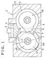
- FIGs. 1 and 2 show a first embodiment of a batch type kneader according to the present invention.
- a kneader 1 is provided with a mixing chamber 3 which is closed by means of a casing 2 and an end frame (not shown), a pair of winged rotors 4A and 4B disposed parallel to each other within the chamber 3 so as to be rotatable in opposite directions, a material push-in ram 6 which is removably fitted to a material supply port 5 formed in the upper center of the chamber 3, and an opening and closing door 8 which is removably fitted to a mixed substance exhaust port 7 formed in the lower center of the chamber 3.
- the casing 2 is provided with a communicating path 9 in such a way that both rotors 4A and 4B are communicated with each other over almost the entire length of the chamber 3.
- a constant clearance S (a tip clearance) is formed between an interior wall surface of the chamber 3 and an outer circumferential surface, i.e., a land surface 10A of a wing 10 (which is also referred to as tip).
- a ratio S/D of this clearance S to an inner diameter D of the chamber 3 is set in the range of 0.01-0.02.
- the wings of one rotor 4A consist of a center wing 11 disposed at the axial center of the rotor 4A, and first to third end wings 12, 13 and 13' disposed on both axial ends of the rotor 4A.
- the first end wing 12 and the second end wing 13 of the end wings 12, 13 and 13' that are disposed at one end of the rotor have the same direction of torsion as the center wing 11, but the third end wing 13' disposed at the other end has a direction of torsion which is opposite to that of the center wing 11.
- Torsional angles ⁇ with respect to the axes of the wings 11, 12, 13 and 13' are equal to each other.
- the length of the first end wing 12 in the axial direction is set to less than half the length of the center wing 11 in the axial direction.
- the second end wing 13 is set so as to be shorter than the first end wing 12, and the length of the third end wing 13' on the opposite side is set so as to be the same as that of the second end wing 13.
- the wings of the other rotor 4B consist of a center wing 14 and an end wing 15 as illustrated by a dot line in Fig. 2. Torsional angles ⁇ of the center wing 14 and the end wing 15 are equal to each other, and the direction of torsion of these wings is opposite to that of the center wing 11. Moreover, both center wings 11 and 14 mesh with each other.
- Torsional angles ⁇ with respect to the wings 11, 12, 13, 13', 14 and 15 are equal to each other and are set to less than 50°.
- the lengths l of the center wings 11 and 14 of both rotors 4A and 4B in the axial direction are equal to each other, and a ratio l/L of the length l to the length L of both the rotors 4A and 4B is set to 0.6 or less.
- a ratio a/L of the lengths a (that is, the distances from the ends of the rotor to the wing) of portions without wings at both ends of the center wings 11 and 14 in the axial direction to the length L of the rotors 4A and 4B is set to not greater than 0.2.
- the lengths of the end wings 12 and 15 of the rotors 4A and 4B are equal to each other, and are set to half the length L of the rotors 4A and 4B.
- the reason for setting the torsional angle ⁇ of each wing of the rotors 4A and 4B to less than 50° is why a force for causing material to flow in the axial direction is increased by means of the rotation of the rotors 4A and 4B when the torsional angle ⁇ exceeds 50°, thereby resulting in uneven mixing of the material.
- the ratios l/L and a/L of the length l of each of the center wings 11 and 14 of the rotor 4A and 4B and the length a of the portions without wings of the rotors in the axial direction to the length L in the direction of the axis of the rotors are set to more than 0.6 and not greater than 0.2, respectively.
- a constant quantity of material and compounding agent introduced through the material supply port 5 are forced in between the rotors 4A and 4B which rotate in opposite directions by means of the push-in ram 6, and they are drawn into the chamber 3.
- the even mixing of the entire material is started using the wings 11-15 of both rotors 4A and 4B.
- a constant optimum shearing force acts on the material between an interior wall surface of the chamber 3 and the rotors 4A and 4B, and also between the rotors 4A and 4B. Then, the temperature of the material becomes appropriate, and the flow of material is carried out in an averaged manner in the axial direction as well as between the rotors 4A and 4B by virtue of the optimum length of the center wings 11 and 14 and the distance between the ends of the rotor and the center wing. As a result of this, the mixing of the material is speeded up and efficiently carried out without variations. Moreover, the time required for drawing the material into the chamber and mixing performance are improved, and therefore it is possible to reduce a mixing time and improve productivity.
- Figs. 3 through 6 show the results of a test which was conducted for the mixing of a tire compounding agent (NBR-based carbon master batch) using a first conventional example or a comparative example (which is a kneader of this embodiment having a torsional angle of 50°) and a kneader of this embodiment which has a ratio S/D of 0.014, a torsional angle of 40°, a ratio l/L of 0.7 and a ratio a/L of 0.15.
- NBR-based carbon master batch a first conventional example or a comparative example (which is a kneader of this embodiment having a torsional angle of 50°) and a kneader of this embodiment which has a ratio S/D of 0.014, a torsional angle of 40°, a ratio l/L of 0.7 and a ratio a/L of 0.15.
- the degree of decrease of the Mooney viscosity relative to a mixing time obtained by the kneader of the present invention has a steeper inclination compared to that obtained by the first conventional example. It is also apparent that the kneader of this embodiment is superior to the first conventional example with respect to specific energy relative to a mixing time as shown in Fig. 4. Thus, it is possible for the kneader of this embodiment to obtain larger specific energy faster than the first conventional example, and therefore the kneader of this embodiment is more efficient. In addition, as shown in Fig.
- the kneader of this embodiment is faster than the comparative example.
- the kneader of this embodiment is lower than the comparative example as shown in Fig. 6. Accordingly, it is obvious that the kneader of this embodiment has a better mixing performance.
- the present invention is not limited to the embodiment mentioned above.
- the second end wing 13 may be removed from the rotor, or the second end wing 13 may be provided on both rotors. It is not necessary for the torsional angle ⁇ of the end wings 12 and 15 to be made equal to that of the center wings 11 and 14, and the design of the torsional angle of the end wings may be changed appropriately.
- Fig. 7 shows a batch type kneader in a second embodiment according to the present invention.
- the construction of this kneader is basically identical with that of the kneader shown in Fig. 1.
- the feature of this kneader resides in a clearance between the pair of rotors 4A and 4B.
- each of the wings 10 also called “tip”
- the wings 10 mesh with each other when the rotors 4A and 4B are arranged parallel to each other within the chamber 3.
- the wings 10 are designed in such a way that a clearance C between opposite acting surfaces 10B of the wings 10, when the wings mesh with each other, becomes constant along a line G that interconnects the axial centers O of the rotors.
- This clearance C becomes optimum in the range of 5-20 mm. If the value becomes smaller than the minimum value in this range, the clearance between the rotors 4A and 4B will become narrower, which will in turn make the biting of the material poor. Contrary to this, if the value becomes larger than the maximum value in the range, the clearance will become wider, and a shearing force occurring between the rotors will not act appropriately on the material.
- a constant quantity of material and compounding agent introduced from the material supply port 5 is forced in between the rotors 4A and 4B by means of the push-in ram 6.
- the even mixing of the entire material is started by means of the wings 10 of the rotors 4A and 4B.
- a constant optimum shearing force acts on the material in the tip clearance S between the chamber 3 and the rotors 4A and 4B, and also in between the acting surfaces 10B of the wings 10 which mesh with each other. In this way, the performance for mixing material by virtue of fractionization is improved.
- the material which stays at and below the material supply port 5 of the chamber 3 and is not yet drawn into the chamber 3, is sequentially drawn into the chamber.
- the compounding agent other than the main body of the material for example, rubber
- the time during which all of the introduced material are simultaneously mixed in the chamber 3 becomes longer than the mixing time required for one mixing step (one batch), so that a mixing state every one batch (one step) becomes even, and therefore mixing performance is improved.
- the door 8 is opened, and the push-in ram 6 is pulled out. Then, the material which has been mixed, i.e., a mixed substance, is taken out of the exhaust port 7.
- Figs. 8 and 9 show the results of a test which was conducted for mixing together rubber material (NBR) and carbon using the kneader 1 of the embodiment shown in Fig. 7 and the conventional kneader.
- NBR rubber material
- Figs. 8 and 9 show the results of a test which was conducted for mixing together rubber material (NBR) and carbon using the kneader 1 of the embodiment shown in Fig. 7 and the conventional kneader.
- the ram sheet time obtained by the kneader of the second embodiment becomes shorter over the entire range of the filling rate.
- the Mooney viscosity HS1+4 (100 °C) relative to the filling rate becomes lower over the entire range of the filling rate in the case of the kneader of the second embodiment, compared with the conventional example, so that superior results were obtained.
- Fig. 10 shows a third embodiment of the batch type kneader according to the present invention.
- the construction of the kneader of this embodiment is the same as that of the kneader shown in Fig. 7, except for the following points.
- a distance d (along the line G interconnecting the center axes O of both rotors), between an outer circumferential end surface 10A of the wing 10 of each of the rotors 4A and 4B and a circumferential surface 4C of the barrel of the rotor, is constant, and a ratio d/A of the distance d to a distance A between the axes of the rotors 4A and 4B is set in the range of 0.01-0.04.
- the ratio d/A is optionally selected and set in the range of 0.01-0.04 in response to a value of the physical property of a required mixed material.
- the width of the outer circumferential surface 10A of the wing is set large because cooling efficiency is improved in the case of a meshing type kneader. For these reasons, it is possible to expect superior material mixing action by virtue of the optimum shearing force and resultant fractionization of the material occurring between the end surface 10A and the circumferential surface 4C of the barrel of the rotor.
- the material can be fractionized into small pieces by obtaining an optimum shearing force, and hence it is also possible to expect the improved property (capability) of biting the material.
- the ratio d/A is set in the range of 0.01-0.04. If the ratio d/A is more than 0.04, the distance d of the opposite surfaces, i.e., a space, will become larger. This might result in the generation of residual material, and also results in a reduced shearing force and insufficient mixing.
- Figs. 11 and 12 show the results of a test conducted for the mixing together of rubber material (NBR) and carbon using kneaders which respectively have ratios d/A of 0.018, 0.030 and 0.045.
- Fig. 11 shows the relationship between specific energy and the Mooney viscosity MS1+4 (100 °C), and it is evident that a mixed substance having a low Mooney value is obtained. From the relationship between a filling rate and a ram sheet time shown in Fig. 12, it is obvious that the appropriate property of biting the material is obtained.
- Fig. 13 shows a batch type kneader in a fourth embodiment according to the present invention.
- the construction of the kneader of this embodiment is the same as that of the kneaders shown in Figs. 1, 7 and 10, except for the shape of the wing 10.
- the wing 10 of each rotor 4 is provided with a material biting angled portion K where a rotor front surface 10C, which becomes a front surface in the direction of rotation, meets the land surface 10A.
- the material biting angled portion K is formed into a two-stage chamfered shape consisting of a first corner 16 and a second corner 17 respectively defined by two lines which connect the front surface to the land surface.
- the lengths m of the corners 16 and 17 are substantially equal to each other.
- the front surface 10C, the first corner 16, the second corner 17 and the land surface 10A are continuous with each other in the form of a substantially smooth surface.
- the lengths m of the first and second corners 16 and 17 of the material biting chamfered angled portion K are made equal to each other.
- it becomes possible to ensure a low-temperature mixing function and to improve mixing performance by setting the lengths m of the first and second corners 16 and 17 so as not to exceed 20% of a normal land width, in other words, by setting the land width so as not to be less than 20% of the normal land width.
- the material biting angled portion K is formed in the shape of a two-stage structure, and therefore the amount of material passing through a space between the land surface 10A and the interior surface of the chamber 3 is increased. As a result of this, the smashing and fractionization of bale-shaped rubber material, or the like, which are caused by the shearing action in the early stage of mixing are effectively carried out. It is possible to increase the material biting capability and the mixing performance.
- the angled biting portion K of the wing 10 of the rotor 4 is formed into a two-stage structure made up of two corners 16 and 17. This increases the amount of material passing through this angled portion K. Accordingly, the time required for drawing material is reduced, and the initiation of mixing of the entire material is speeded up, so that sufficient mixing is effectively carried out.
- the material is fractionized into small pieces even in between the wings 10 of the rotor and the circumferential surface of the body of the rotor by means of an optimum shearing force.
- the material actively passes through the space between the wings 10 and the interior wall surface of the chamber 3, and a ratio of the material which is mixed is increased. Thereby, the Mooney viscosity and the degree of dispersion of carbon are improved.
- mixed material can be homogenized.
- the material is thrust from the inside of the chamber 3 to the supply port, and an upwardly pushing force of the push-in ram 6 is reduced. Hence, it only needs a small force to downwardly press the ram 6. This is advantageous in designing the strength of the rotors.
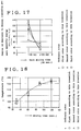
- Figs. 15 through 18 show the results of a test which was conducted using an NBR-based carbon master batch as a rubber material compounding agent.
- ⁇ designates the shape of a first rotor according to the present invention in which the lengths m of the corners shown in Fig. 14A are equal to each other; ⁇ , the shape of a second rotor according to the present invention in which the lengths m of the corners are different from each other; ⁇ , the shape of a third rotor according to the present invention in which the lengths m of the corners shown in Fig. 14B are equal to each other and, particularly, a land width remains to 30% of an ordinary land width; and x, an ordinary rotor (having one angled biting portion).
- Fig. 15 shows variations in consumption of specific energy, which is made dimensionless by means of the shape of an ordinary rotor, relative to a material mixing time when a test was conducted using three types of rotors according to this invention, each having a different shape and size.
- the energy consumption of each rotor is in the range of 110-140% with respect to an ordinary rotor up to about sixty seconds in the early stage of mixing. In view of this fact, it is apparent that the amount of material which is drawn into the early stage of mixing is large.
- Fig. 16 shows a ram sheet time, which is made dimensionless by means of the shape of an ordinary rotor, with respect to the number of revolutions of the rotors when a test was conducted using three types of rotors according to the present invention, each having a different size and shape.
- the ram sheet time that represents the property of biting material is significantly reduced, and each of the rotors has only 70-80% of the ram sheet time which is obtained using an ordinary rotor. In this way, the improvement of the capability of biting the material is evident.
- the ram sheet time is reduced in rotation of the rotor.
- Fig. 17 shows the degree of decreases in Mooney viscosity per unit specific energy per unit mixing time (thirty seconds) when a test was conducted using three types of rotors according to the present invention, each having a different shape and size, and an ordinary rotor.
- the degree of decreases in Mooney viscosity is larger in the initial sixty seconds of mixing compared with that obtained by the ordinary rotor. In the period between 90 to 120 seconds, a large degree of decreases in viscosity is still observed in the case of the ordinary rotor.
- the degree of decreases in viscosity is about to be reduced and stabilized.
- a 5-6 % drop of the Mooney viscosity was observed in the case of the rotors of the present invention compared with the ordinary rotor.
- the present invention is not limited to the embodiments mentioned above, and as a matter of course the design of the batch type kneader according to the present invention can be appropriately changed. Moreover, it is possible to combine the constructions of the embodiments shown in Figs. 1, 7, 10 and 13 with each other.
- the batch type kneader according to the present invention is preferably used in mixing polymeric materials, such as a rubber material.
Landscapes
- Engineering & Computer Science (AREA)
- Mechanical Engineering (AREA)
- Processing And Handling Of Plastics And Other Materials For Molding In General (AREA)
- Mixers Of The Rotary Stirring Type (AREA)
Applications Claiming Priority (10)
| Application Number | Priority Date | Filing Date | Title |
|---|---|---|---|
| JP7824393 | 1993-04-05 | ||
| JP5078244A JP2803961B2 (ja) | 1993-04-05 | 1993-04-05 | 密閉式混練機 |
| JP78244/93 | 1993-04-05 | ||
| JP5078243A JP2803960B2 (ja) | 1993-04-05 | 1993-04-05 | 密閉式混練機 |
| JP78243/93 | 1993-04-05 | ||
| JP7824493 | 1993-04-05 | ||
| JP8212493 | 1993-04-08 | ||
| JP5082124A JP2759038B2 (ja) | 1993-04-08 | 1993-04-08 | 密閉式混練機のロータ |
| JP82124/93 | 1993-04-08 | ||
| PCT/JP1994/000546 WO1994022649A1 (en) | 1993-04-05 | 1994-04-01 | Hermetically sealed kneader |
Publications (3)
| Publication Number | Publication Date |
|---|---|
| EP0652091A1 true EP0652091A1 (de) | 1995-05-10 |
| EP0652091A4 EP0652091A4 (de) | 1995-09-27 |
| EP0652091B1 EP0652091B1 (de) | 1999-07-07 |
Family
ID=27302651
Family Applications (1)
| Application Number | Title | Priority Date | Filing Date |
|---|---|---|---|
| EP94910591A Expired - Lifetime EP0652091B1 (de) | 1993-04-05 | 1994-04-01 | Hermetisch abgeschlossener kneter |
Country Status (4)
| Country | Link |
|---|---|
| US (1) | US5520455A (de) |
| EP (1) | EP0652091B1 (de) |
| DE (1) | DE69419385T2 (de) |
| WO (1) | WO1994022649A1 (de) |
Cited By (2)
| Publication number | Priority date | Publication date | Assignee | Title |
|---|---|---|---|---|
| DE29604647U1 (de) * | 1996-03-13 | 1996-05-15 | Fa. Renate Weber Ingenieurbüro und Spezialmaschinenbau, 57482 Wenden | Vorrichtung zum Herstellen von Gummi und/oder Kunststoff |
| EP1352725A1 (de) * | 2000-10-17 | 2003-10-15 | Moriyama Co., Ltd. | Abgeschlossener Kneter |
Families Citing this family (15)
| Publication number | Priority date | Publication date | Assignee | Title |
|---|---|---|---|---|
| JPH09124797A (ja) * | 1995-11-01 | 1997-05-13 | Toray Dow Corning Silicone Co Ltd | オルガノポリシロキサン生ゴムの連続的乳化方法 |
| BR9909230A (pt) | 1998-03-28 | 2000-11-28 | Skinner Engine Co | Máquinas e rotores internos para mistura em batelada |
| IT1319996B1 (it) * | 2000-03-23 | 2003-11-12 | Maris Flli Spa | Elemento di miscelazione per vite di estrusore bivite corotante edestrusore che lo comprende. |
| JP4236963B2 (ja) * | 2003-03-12 | 2009-03-11 | 株式会社神戸製鋼所 | 密閉式混練機 |
| DE102004051063A1 (de) * | 2004-10-19 | 2006-04-20 | Thyssenkrupp Elastomertechnik Gmbh | Innenmischer zum Kneten von plastischen Massen |
| US8047701B2 (en) * | 2005-07-26 | 2011-11-01 | Kobe Steel, Ltd. | Batch mixer |
| US7476017B2 (en) * | 2005-09-29 | 2009-01-13 | Jacques Mortimer | Intermeshing kneader with tilting mixing chamber |
| US7677789B2 (en) * | 2006-06-16 | 2010-03-16 | Bridgestone Americas Tire Operations, Llc | Mixer rotor with spiral core ribs |
| JP4568785B2 (ja) * | 2009-01-19 | 2010-10-27 | 株式会社神戸製鋼所 | 混練ロータ |
| JP4542605B1 (ja) * | 2009-04-15 | 2010-09-15 | 株式会社神戸製鋼所 | 密閉式混練機及び混練ロータ |
| RU2597080C2 (ru) | 2010-12-31 | 2016-09-10 | Бриджстоун Корпорейшн | Стабилизация полимеров, содержащих гидролизуемые функциональные группы |
| US9000070B2 (en) | 2011-10-19 | 2015-04-07 | Bridgestone Corporation | Mixing of telechelic rubber formulations |
| JP5792650B2 (ja) * | 2012-01-31 | 2015-10-14 | 株式会社神戸製鋼所 | 混練ロータ、およびそれを備える密閉式混練機 |
| DE102018201482A1 (de) * | 2018-01-31 | 2019-08-01 | Harburg-Freudenberger Maschinenbau Gmbh | Innenmischer |
| JP7288378B2 (ja) * | 2019-10-01 | 2023-06-07 | 株式会社日本製鋼所 | 樹脂用押出機、ロータ型スクリュ及び樹脂製造方法 |
Citations (3)
| Publication number | Priority date | Publication date | Assignee | Title |
|---|---|---|---|---|
| GB2028153A (en) * | 1978-08-24 | 1980-03-05 | Werner & Pfleiderer | Internal mixer for kneading plastic compositions particularly rubber |
| EP0213882A2 (de) * | 1985-08-22 | 1987-03-11 | Kabushiki Kaisha Kobe Seiko Sho | Geschlossene Mischungsmaschine |
| EP0346680A1 (de) * | 1988-06-16 | 1989-12-20 | COMPAGNIE GENERALE DES ETABLISSEMENTS MICHELIN-MICHELIN & CIE | Innenmischer mit verbesserten Rotoren |
Family Cites Families (11)
| Publication number | Priority date | Publication date | Assignee | Title |
|---|---|---|---|---|
| DE137905C (de) * | ||||
| US4184773A (en) * | 1977-08-11 | 1980-01-22 | Usm Corporation | Mixer rotor with a shear edge |
| IT1191304B (it) * | 1978-06-23 | 1988-03-07 | Kobe Steel Ltd | Macchina per la mescola e impastatrice |
| JPS5931369B2 (ja) * | 1980-02-16 | 1984-08-01 | 株式会社神戸製鋼所 | 密閉型混練捏和装置のロ−タ |
| JPS5931369A (ja) * | 1982-08-12 | 1984-02-20 | 株式会社ユ−シン | シリンダ錠におけるキ−插脱検出装置 |
| JPS631093A (ja) * | 1986-06-20 | 1988-01-06 | 松下電器産業株式会社 | 電子部品搭載用基板装置 |
| JPH0659646B2 (ja) * | 1986-08-13 | 1994-08-10 | 株式会社ブリヂストン | ゴム状物の混練装置 |
| JPH07118850B2 (ja) * | 1986-11-27 | 1995-12-18 | 東京電力株式会社 | 架空配電線用碍子脱着装置 |
| JPH061364Y2 (ja) * | 1987-02-27 | 1994-01-12 | 株式会社神戸製鋼所 | 密閉型混練機 |
| JPS63306006A (ja) * | 1987-06-08 | 1988-12-14 | Kobe Steel Ltd | 密閉型混練機 |
| JP2639097B2 (ja) * | 1989-05-12 | 1997-08-06 | 日本合成ゴム株式会社 | インターナルミキサー |
-
1994
- 1994-04-01 DE DE69419385T patent/DE69419385T2/de not_active Expired - Lifetime
- 1994-04-01 US US08/338,521 patent/US5520455A/en not_active Expired - Lifetime
- 1994-04-01 WO PCT/JP1994/000546 patent/WO1994022649A1/ja active IP Right Grant
- 1994-04-01 EP EP94910591A patent/EP0652091B1/de not_active Expired - Lifetime
Patent Citations (3)
| Publication number | Priority date | Publication date | Assignee | Title |
|---|---|---|---|---|
| GB2028153A (en) * | 1978-08-24 | 1980-03-05 | Werner & Pfleiderer | Internal mixer for kneading plastic compositions particularly rubber |
| EP0213882A2 (de) * | 1985-08-22 | 1987-03-11 | Kabushiki Kaisha Kobe Seiko Sho | Geschlossene Mischungsmaschine |
| EP0346680A1 (de) * | 1988-06-16 | 1989-12-20 | COMPAGNIE GENERALE DES ETABLISSEMENTS MICHELIN-MICHELIN & CIE | Innenmischer mit verbesserten Rotoren |
Non-Patent Citations (1)
| Title |
|---|
| See also references of WO9422649A1 * |
Cited By (2)
| Publication number | Priority date | Publication date | Assignee | Title |
|---|---|---|---|---|
| DE29604647U1 (de) * | 1996-03-13 | 1996-05-15 | Fa. Renate Weber Ingenieurbüro und Spezialmaschinenbau, 57482 Wenden | Vorrichtung zum Herstellen von Gummi und/oder Kunststoff |
| EP1352725A1 (de) * | 2000-10-17 | 2003-10-15 | Moriyama Co., Ltd. | Abgeschlossener Kneter |
Also Published As
| Publication number | Publication date |
|---|---|
| WO1994022649A1 (en) | 1994-10-13 |
| DE69419385T2 (de) | 2000-03-30 |
| EP0652091A4 (de) | 1995-09-27 |
| EP0652091B1 (de) | 1999-07-07 |
| DE69419385D1 (de) | 1999-08-12 |
| US5520455A (en) | 1996-05-28 |
Similar Documents
| Publication | Publication Date | Title |
|---|---|---|
| EP0652091B1 (de) | Hermetisch abgeschlossener kneter | |
| EP0848988B1 (de) | Innenmischer | |
| US4752135A (en) | Mixing apparatus and methods | |
| EP1661679B1 (de) | Chargenmischer und Rotor dafür | |
| US4652138A (en) | Single screw kneading extruder | |
| US6136246A (en) | Screw extruder with improved dispersive mixing elements | |
| EP2095924B1 (de) | Knetschraube, zweischneckenextruder enthaltend ein paar solcher schrauben, und verfahren zur herstellung einer solchen knetschraube | |
| JPH0639096B2 (ja) | 密閉形混合機 | |
| US4859074A (en) | Closed mixing machine | |
| JP2001522736A (ja) | いろいろな異なる分散混合素子を備えたスクリュー押出機 | |
| US7566163B2 (en) | Screw set for extruder | |
| CA2428700C (en) | Four wing, non-intermeshing rotors for synchronous drive to provide improved dispersive and distributive mixing in internal batch mixers | |
| JPS5931369B2 (ja) | 密閉型混練捏和装置のロ−タ | |
| JP4568785B2 (ja) | 混練ロータ | |
| JP5792650B2 (ja) | 混練ロータ、およびそれを備える密閉式混練機 | |
| EP1352725A1 (de) | Abgeschlossener Kneter | |
| JP3938683B2 (ja) | ゴムあるいはゴム系組成物の混練装置 | |
| JP2803961B2 (ja) | 密閉式混練機 | |
| JPH06285349A (ja) | 密閉式混練機 | |
| JP2002526280A (ja) | 同時回転する双軸押し出し機 | |
| JPH08108429A (ja) | ポリマー中に含まれるゲルの消去方法及びその装置 | |
| JPH06285351A (ja) | 密閉式混練機のロータ | |
| CA1316910C (en) | Extruder and continuous mixer arrangement for producing an at least partially baked product having a cookie-like crumb structure the extruder including a microware applicator | |
| JPH0233871Y2 (de) | ||
| EP1185404A2 (de) | Mischmaschinen |
Legal Events
| Date | Code | Title | Description |
|---|---|---|---|
| PUAI | Public reference made under article 153(3) epc to a published international application that has entered the european phase |
Free format text: ORIGINAL CODE: 0009012 |
|
| 17P | Request for examination filed |
Effective date: 19941129 |
|
| AK | Designated contracting states |
Kind code of ref document: A1 Designated state(s): DE IT |
|
| A4 | Supplementary search report drawn up and despatched | ||
| AK | Designated contracting states |
Kind code of ref document: A4 Designated state(s): DE IT |
|
| 17Q | First examination report despatched |
Effective date: 19970203 |
|
| GRAG | Despatch of communication of intention to grant |
Free format text: ORIGINAL CODE: EPIDOS AGRA |
|
| RTI1 | Title (correction) | ||
| GRAG | Despatch of communication of intention to grant |
Free format text: ORIGINAL CODE: EPIDOS AGRA |
|
| GRAH | Despatch of communication of intention to grant a patent |
Free format text: ORIGINAL CODE: EPIDOS IGRA |
|
| GRAH | Despatch of communication of intention to grant a patent |
Free format text: ORIGINAL CODE: EPIDOS IGRA |
|
| GRAA | (expected) grant |
Free format text: ORIGINAL CODE: 0009210 |
|
| AK | Designated contracting states |
Kind code of ref document: B1 Designated state(s): DE IT |
|
| RTI1 | Title (correction) |
Free format text: HERMETICALLY SEALED KNEADER |
|
| REF | Corresponds to: |
Ref document number: 69419385 Country of ref document: DE Date of ref document: 19990812 |
|
| ITF | It: translation for a ep patent filed | ||
| PLBE | No opposition filed within time limit |
Free format text: ORIGINAL CODE: 0009261 |
|
| STAA | Information on the status of an ep patent application or granted ep patent |
Free format text: STATUS: NO OPPOSITION FILED WITHIN TIME LIMIT |
|
| 26N | No opposition filed | ||
| PG25 | Lapsed in a contracting state [announced via postgrant information from national office to epo] |
Ref country code: IT Free format text: LAPSE BECAUSE OF NON-PAYMENT OF DUE FEES Effective date: 20050401 |
|
| PGRI | Patent reinstated in contracting state [announced from national office to epo] |
Ref country code: IT Effective date: 20080301 |
|
| PGFP | Annual fee paid to national office [announced via postgrant information from national office to epo] |
Ref country code: DE Payment date: 20130327 Year of fee payment: 20 |
|
| PGFP | Annual fee paid to national office [announced via postgrant information from national office to epo] |
Ref country code: IT Payment date: 20130423 Year of fee payment: 20 |
|
| REG | Reference to a national code |
Ref country code: DE Ref legal event code: R071 Ref document number: 69419385 Country of ref document: DE |
|
| PG25 | Lapsed in a contracting state [announced via postgrant information from national office to epo] |
Ref country code: DE Free format text: LAPSE BECAUSE OF EXPIRATION OF PROTECTION Effective date: 20140402 |