EP0651237A1 - Procédé pour déterminer la température d'un objet - Google Patents
Procédé pour déterminer la température d'un objet Download PDFInfo
- Publication number
- EP0651237A1 EP0651237A1 EP94115848A EP94115848A EP0651237A1 EP 0651237 A1 EP0651237 A1 EP 0651237A1 EP 94115848 A EP94115848 A EP 94115848A EP 94115848 A EP94115848 A EP 94115848A EP 0651237 A1 EP0651237 A1 EP 0651237A1
- Authority
- EP
- European Patent Office
- Prior art keywords
- temperature
- temperature sensor
- sensors
- fault tolerance
- sensor
- Prior art date
- Legal status (The legal status is an assumption and is not a legal conclusion. Google has not performed a legal analysis and makes no representation as to the accuracy of the status listed.)
- Withdrawn
Links
- 238000000034 method Methods 0.000 title claims abstract description 9
- 238000012935 Averaging Methods 0.000 claims description 7
- 238000002485 combustion reaction Methods 0.000 description 7
- 230000001419 dependent effect Effects 0.000 description 7
- 239000000498 cooling water Substances 0.000 description 5
- 238000010586 diagram Methods 0.000 description 3
- 238000012937 correction Methods 0.000 description 2
- 238000013461 design Methods 0.000 description 2
- 238000011156 evaluation Methods 0.000 description 2
- 238000012545 processing Methods 0.000 description 2
- 230000009467 reduction Effects 0.000 description 2
- 230000015572 biosynthetic process Effects 0.000 description 1
- 230000003197 catalytic effect Effects 0.000 description 1
- 230000008859 change Effects 0.000 description 1
- 238000005352 clarification Methods 0.000 description 1
- 230000003247 decreasing effect Effects 0.000 description 1
- 230000006872 improvement Effects 0.000 description 1
- 238000002347 injection Methods 0.000 description 1
- 239000007924 injection Substances 0.000 description 1
- 238000005259 measurement Methods 0.000 description 1
- 230000004044 response Effects 0.000 description 1
Images
Classifications
-
- G—PHYSICS
- G01—MEASURING; TESTING
- G01K—MEASURING TEMPERATURE; MEASURING QUANTITY OF HEAT; THERMALLY-SENSITIVE ELEMENTS NOT OTHERWISE PROVIDED FOR
- G01K15/00—Testing or calibrating of thermometers
Definitions
- the invention relates to a method according to the preamble of patent claim 1.
- temperatures of the objects are determined selectively.
- the temperature of an object can also be determined by several temperature sensors. For example, a multitude of temperatures are measured in a motor vehicle.
- the objects are, for example, the various media such as intake air, exhaust gas temperature before and after passing through a catalytic converter, the cooling water temperature or the temperature at defined points on the internal combustion engine.
- Each of these temperature sensors has a tolerance, which is mostly due to the design, which influences the result of an electronic evaluation and processing unit assigned to the temperature sensor.
- the deviation of a temperature sensor for the cooling water is included in the signal for the injection quantity or the ignition timing of the internal combustion engine of the motor vehicle.
- the temperature sensors often also cover a large temperature range, for example the exhaust gas temperature reaches values around 1000 ° C, the fault tolerance also depends on the actual temperature in each case and usually increases with increasing temperature. Especially in the case of a large temperature range, it can be seen that the error tolerance is absolutely also considerable, with the consequence of corresponding uncertainties and tolerances of the signal dependent thereon. In the course of stricter exhaust gas regulations, however, there is an increasing problem.
- the invention has for its object to provide a method of the type mentioned, which provides high accuracy for the temperature determination of an object with little effort.
- the invention requires, on the one hand, that the temperatures determined with both temperature sensors are at least approximately the same. This is the case if the object is without separate temperature exposure over a longer period of time and the thermal equilibrium with the environment is present. An example of this is a motor vehicle's rest period of several hours, during which the components of the motor vehicle come at least approximately to ambient temperature. Is that the case, fault-free temperature sensors are required, the temperatures measured by both temperature sensors are the same even if the two temperature sensors are assigned to different objects.
- the temperature in the intake tract of the internal combustion engine is equal to that of the cooling water or that in the exhaust tract, provided that the internal combustion engine has been in operation for a correspondingly long time, for example several hours.
- averaging is carried out in the invention. This can involve the formation of the arithmetic or else the geometric model of the temperatures supplied by the temperature sensors.
- the output signal of the two temperature sensors is corrected.
- the average temperature is assigned to the output signals of both temperature sensors.
- the invention improves if the averaging takes place in accordance with the fault tolerance of the temperature sensors.
- a temperature sensor with a small fault tolerance and a temperature sensor with a large fault tolerance are assumed.
- the output signal of the temperature sensor with a low fault tolerance is weighted more strongly than that of the temperature sensor with a large fault tolerance.
- the weighted (also referred to as weighed) arithmetic mean of the two temperatures is thus determined.
- the smaller the error tolerance of the respective temperature sensor the greater the weighting factor.
- the fault tolerance increases this temperature sensor for the output signal of the temperature sensor with small fault tolerance is not significantly noticeable.
- a further improvement of the invention provides for averaging to take place as a function of the measured temperature.
- the temperature-dependent change in the fault tolerance of the temperature sensors is thus also taken into account and, for example, the weighting factor is assumed to be temperature-dependent if the weighted average is formed.
- the error correction of the temperature sensors can also be carried out with the help of a computer.
- the computer is used to compare the temperatures measured by both temperature sensors.
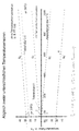
- the diagram shown in the drawing shows the temperature-dependent fault tolerance of two temperature sensors, not shown in detail, of a motor vehicle.
- the first temperature sensor is used to determine the cooling water temperature of an internal combustion engine. It covers a temperature range from around -30 ° C to 150 ° C. Its fault tolerance is a uniform +/- 2.5 K over the entire measuring range. This temperature range including the fault tolerance band is designated by I.
- a second temperature sensor is used to determine the exhaust gas temperature of the internal combustion engine. It has a temperature range from -50 ° C to about 1000 ° C. Its fault tolerance is temperature-dependent and increases with increasing temperature. Furthermore, the tolerance band is significantly larger than in the case of the first temperature sensor. At 0 ° C it ranges from -30 to + 30 ° C, i.e. the temperature sensors of this type used at 0 ° C actually output a temperature value that is between -30 ° and + 30 ° C. The entire temperature tolerance band for the second temperature sensor is designated II.
- the two sensor signals are compared.
- the weighted average of the temperature values supplied by the two temperature sensors is determined.
- the prerequisite for the adjustment is given after the internal combustion engine has been idle for several hours.
- the actual temperature is, for example, 20 ° C, the corresponding value is marked with an x on the temperature scale.
- the temperature error of the second temperature sensor is, for example, 25 ° C. at an actual temperature of 20 ° C.
- the temperature value supplied by the first temperature sensor and taking into account the maximum possible error for this value (+/- 2.5 °)
- the temperature value supplied by the second temperature sensor here is significantly higher than the actual temperature value.
- the temperature value, how it is supplied by the second temperature sensor is therefore adapted. For this purpose, the weighted arithmetic mean of the two temperature values is determined.
- the weighting factor for the temperature value, as supplied by the first temperature sensor, is much higher due to the small maximum error deviation, for example equal to 0.95, while the temperature value of the second temperature sensor is then only weighted with the factor of 0.05.
- the result is a mathematically determined temperature value of, for example, 22 ° for the cooling water and the exhaust gas temperature.
- the tolerance band of the second temperature sensor can be limited to the range which is limited by two lines g1 and g1 'running in mirror image to the temperature scale. These lines run parallel to the specified lines g0 and g0 ', which limit the tolerance band II.
- the weighted arithmetic mean is taken for the starting temperature, here absolutely 20 ° C, from the temperature values T1 and T2 of the temperatures determined by the two temperature sensors.
- the calculated absolute temperature T ar determines.
- the temperature signal measured at an absolute 1000 ° C, here from 1038 ° C, is corrected downwards by the value of x 23 °. This results in the calculated temperature for the second temperature sensor of 1015 ° C.
- the last-mentioned operation presupposes that the temperature response of the temperature sensor is constant over the entire measuring range. If this is not the case, but is dependent on the absolute temperature - a linear dependence is shown in the diagram - this temperature dependency is also taken into account and the difference value of 23 ° C, which is assumed to be 20 ° C, is corrected up or down according to the absolute temperature . This correction can also be carried out with the aid of a table from which a computer takes the correcting value that is valid at the time and applies it to determine the valid temperature.
- the display shows an error tolerance of an additional 12 ° C, which leads to a corrected temperature value of 1003 ° C at an actual 1000 ° C.
Landscapes
- Physics & Mathematics (AREA)
- General Physics & Mathematics (AREA)
- Combined Controls Of Internal Combustion Engines (AREA)
Applications Claiming Priority (2)
| Application Number | Priority Date | Filing Date | Title |
|---|---|---|---|
| DE4337272 | 1993-11-02 | ||
| DE19934337272 DE4337272A1 (de) | 1993-11-02 | 1993-11-02 | Verfahren zur Temperaturbestimmung eines Objekts |
Publications (1)
| Publication Number | Publication Date |
|---|---|
| EP0651237A1 true EP0651237A1 (fr) | 1995-05-03 |
Family
ID=6501547
Family Applications (1)
| Application Number | Title | Priority Date | Filing Date |
|---|---|---|---|
| EP94115848A Withdrawn EP0651237A1 (fr) | 1993-11-02 | 1994-10-07 | Procédé pour déterminer la température d'un objet |
Country Status (2)
| Country | Link |
|---|---|
| EP (1) | EP0651237A1 (fr) |
| DE (1) | DE4337272A1 (fr) |
Cited By (7)
| Publication number | Priority date | Publication date | Assignee | Title |
|---|---|---|---|---|
| EP0816816A1 (fr) * | 1996-06-27 | 1998-01-07 | Bayerische Motoren Werke Aktiengesellschaft, Patentabteilung AJ-3 | Procédé pour simuler, à l'aide d'un modèle, la températue du moyen de refrodissement d'une voiture automobile |
| EP0823620A1 (fr) * | 1996-08-09 | 1998-02-11 | Schott Glaswerke | Méthode pour calibrer des résistances de mesure de la température sur un support en verre, en céramique de verre ou analogue |
| GB2343754A (en) * | 1998-11-13 | 2000-05-17 | Ford Motor Co | Sensor malfunction diagnosis |
| FR2796460A1 (fr) * | 1999-07-16 | 2001-01-19 | Valeo Electronique | Dispositif pour la mesure de temperature a l'interieur d'un habitacle de vehicule automobile et tableau de commande le comportant |
| WO2001035065A1 (fr) * | 1999-11-10 | 2001-05-17 | Robert Bosch Gmbh | Procede pour controler le bon fonctionnement d'un capteur de temperature de gaz d'echappement et/ou pour regler ce dernier |
| EP1102048A1 (fr) * | 1999-11-19 | 2001-05-23 | Heraeus Electro-Nite International N.V. | Méthode de calibration d'un capteur de température |
| US6644850B2 (en) | 2001-05-22 | 2003-11-11 | Bayerische Motoren Werke Aktiengesellschaft | Temperature sensing device for an internal-combustion engine |
Citations (6)
| Publication number | Priority date | Publication date | Assignee | Title |
|---|---|---|---|---|
| DE3145333A1 (de) * | 1981-11-14 | 1983-05-26 | Brown, Boveri & Cie Ag, 6800 Mannheim | Verfahren zum pruefen von temperaturfuehlern |
| JPS6031029A (ja) * | 1983-08-01 | 1985-02-16 | Yamatake Honeywell Co Ltd | 蓄熱量測定方法 |
| JPS60164240A (ja) * | 1984-02-06 | 1985-08-27 | Nippon Denso Co Ltd | 酸素濃度センサ用ヒ−タの制御装置 |
| US4926364A (en) * | 1988-07-25 | 1990-05-15 | Westinghouse Electric Corp. | Method and apparatus for determining weighted average of process variable |
| US5214267A (en) * | 1989-12-15 | 1993-05-25 | Toyota Jidosha Kabushiki Kaisha | Apparatus for controlling heater for heating oxygen sensor |
| US5253190A (en) * | 1992-07-01 | 1993-10-12 | Westinghouse Electric Corp. | Weighted temperature measurement using multiple sensors |
Family Cites Families (5)
| Publication number | Priority date | Publication date | Assignee | Title |
|---|---|---|---|---|
| GB1291827A (en) * | 1968-10-28 | 1972-10-04 | Rosemount Eng Co Ltd | Improvements in or relating to temperature measuring apparatus |
| US4340886A (en) * | 1978-07-03 | 1982-07-20 | Dickey-John Corporation | Bearing and motor temperature monitor |
| US4863279A (en) * | 1988-02-22 | 1989-09-05 | Morris L. Markel | Operative temperature sensing system |
| DE4024863A1 (de) * | 1990-08-04 | 1992-02-06 | Werner & Pfleiderer | Verfahren zur temperaturmessung des mischgutes in einer mischkammer eines kneters |
| DE4110671A1 (de) * | 1991-04-03 | 1992-10-08 | Jenoptik Jena Gmbh | Verfahren und anordnung zur temperaturregelung eines geraetes |
-
1993
- 1993-11-02 DE DE19934337272 patent/DE4337272A1/de not_active Withdrawn
-
1994
- 1994-10-07 EP EP94115848A patent/EP0651237A1/fr not_active Withdrawn
Patent Citations (6)
| Publication number | Priority date | Publication date | Assignee | Title |
|---|---|---|---|---|
| DE3145333A1 (de) * | 1981-11-14 | 1983-05-26 | Brown, Boveri & Cie Ag, 6800 Mannheim | Verfahren zum pruefen von temperaturfuehlern |
| JPS6031029A (ja) * | 1983-08-01 | 1985-02-16 | Yamatake Honeywell Co Ltd | 蓄熱量測定方法 |
| JPS60164240A (ja) * | 1984-02-06 | 1985-08-27 | Nippon Denso Co Ltd | 酸素濃度センサ用ヒ−タの制御装置 |
| US4926364A (en) * | 1988-07-25 | 1990-05-15 | Westinghouse Electric Corp. | Method and apparatus for determining weighted average of process variable |
| US5214267A (en) * | 1989-12-15 | 1993-05-25 | Toyota Jidosha Kabushiki Kaisha | Apparatus for controlling heater for heating oxygen sensor |
| US5253190A (en) * | 1992-07-01 | 1993-10-12 | Westinghouse Electric Corp. | Weighted temperature measurement using multiple sensors |
Non-Patent Citations (3)
| Title |
|---|
| ANONYMOUS: "AUTOMATIC AUTOMOTIVE VEHICLE TEMPERATURE VERIFICATION", IBM TECHNICAL DISCLOSURE BULLETIN, vol. 29, no. 8, January 1987 (1987-01-01), NEW YORK US, pages 3513 - 3515 * |
| HELEN HOERSCH (EDITOR): "MANUAL ON THE USE OF THERMOCOUPLES IN TEMPERATURE MEASUREMENT", 1981, ASTM, PHILADELPHIA, -1981 * |
| PATENT ABSTRACTS OF JAPAN vol. 10, no. 7 (P - 419) 11 January 1986 (1986-01-11) * |
Cited By (10)
| Publication number | Priority date | Publication date | Assignee | Title |
|---|---|---|---|---|
| EP0816816A1 (fr) * | 1996-06-27 | 1998-01-07 | Bayerische Motoren Werke Aktiengesellschaft, Patentabteilung AJ-3 | Procédé pour simuler, à l'aide d'un modèle, la températue du moyen de refrodissement d'une voiture automobile |
| EP0823620A1 (fr) * | 1996-08-09 | 1998-02-11 | Schott Glaswerke | Méthode pour calibrer des résistances de mesure de la température sur un support en verre, en céramique de verre ou analogue |
| US6155711A (en) * | 1996-08-09 | 2000-12-05 | Schott Glas | Method of calibrating temperature-measuring resistors on a glass, glass-ceramic, or similar substrate |
| GB2343754A (en) * | 1998-11-13 | 2000-05-17 | Ford Motor Co | Sensor malfunction diagnosis |
| US6091324A (en) * | 1998-11-13 | 2000-07-18 | Ford Motor Company | Comparing sensor outputs to distinguish between sensor faults and extreme temperature conditions |
| GB2343754B (en) * | 1998-11-13 | 2003-03-26 | Ford Motor Co | Comparing sensor outputs to distinguish between sensor faults and extreme temperature conditions |
| FR2796460A1 (fr) * | 1999-07-16 | 2001-01-19 | Valeo Electronique | Dispositif pour la mesure de temperature a l'interieur d'un habitacle de vehicule automobile et tableau de commande le comportant |
| WO2001035065A1 (fr) * | 1999-11-10 | 2001-05-17 | Robert Bosch Gmbh | Procede pour controler le bon fonctionnement d'un capteur de temperature de gaz d'echappement et/ou pour regler ce dernier |
| EP1102048A1 (fr) * | 1999-11-19 | 2001-05-23 | Heraeus Electro-Nite International N.V. | Méthode de calibration d'un capteur de température |
| US6644850B2 (en) | 2001-05-22 | 2003-11-11 | Bayerische Motoren Werke Aktiengesellschaft | Temperature sensing device for an internal-combustion engine |
Also Published As
| Publication number | Publication date |
|---|---|
| DE4337272A1 (de) | 1995-05-04 |
Similar Documents
| Publication | Publication Date | Title |
|---|---|---|
| DE4039876B4 (de) | Vorrichtung zum Regeln des Luft-Kraftstoff-Verhältnisses für einen Motor | |
| DE69617513T2 (de) | Nichtlineare dynamische Transformation zur Korrektur einer torsionsschwingungsbehafteten Kurbelwellenbeschleunigung | |
| DE4120388C2 (de) | Verfahren zur Temperaturerfassung | |
| DE69423095T2 (de) | System zur bestimmung von fehlzündungen bei einer brennkraftmaschine | |
| AT4801U2 (de) | Verfahren und vorrichtung zum bereitstellen eines kurbelwinkelbasierten signalverlaufes | |
| EP0929794B1 (fr) | Procede et dispositif pour la correction de tolerances d'une roue indicatrice | |
| EP0457033B1 (fr) | Dispositif pour détecter un paramètre de fonctionnement variable | |
| DE102005042794B4 (de) | Automatisches Kalibrierverfahren für ein Zündaussetzererfassungssystem eines Motors | |
| DE68909496T2 (de) | Elektrisches Steuergerät für Kraftfahrzeug und Kompensationsverfahren der Zeitverzögerung von Messdaten. | |
| EP1715165B1 (fr) | Procédé et dispositif de diagnostic de défauts pour moteurs thermiques | |
| DE3546168A1 (de) | Anordnung zum regeln des zuendzeitpunkts eines verbrennungsmotors | |
| DE19652026A1 (de) | Vorrichtung und Verfahren zur Luftmengenmessung | |
| DE19545924B4 (de) | Verfahren und Vorrichtungen zum Steuern des Luft/Kraftstoffverhältnis-Lernens eines Motors mit innerer Verbrennung | |
| DE3513086C2 (fr) | ||
| DE3721010A1 (de) | Verfahren und vorrichtung zum detektieren des maximalzylinderdruckwinkels bei einer brennkraftmaschine | |
| DE4238807A1 (en) | IC engine exhaust gas catalyser monitoring system - uses cross-correlation function for signals from oxygen@ sensors inserted in exhaust line before and after catalyser | |
| EP0651237A1 (fr) | Procédé pour déterminer la température d'un objet | |
| DE69932523T2 (de) | Verfahren und system zum erfassen von verbrennungsaussetzern unter verwendung einer synchronen korrektur | |
| DE102008052245A1 (de) | Verfahren zum Ermitteln einer kurbelwellentorsionsoptimalen Betriebsweise einer Brennkraftmaschine | |
| DE102016006327A1 (de) | Verfahren und Vorrichtung zum Adaptieren eines Abgasrückführventils | |
| DE3819016A1 (de) | System zum erfassen anormaler betriebszustaende eines verbrennungsmotors | |
| DE3447629A1 (de) | Signalverarbeitungssystem fuer einen kraftfahrzeug-beschleunigungsfuehler | |
| WO1997022786A2 (fr) | Procede pour detecter des fluctuations cycliques de la combustion dans un moteur a combustion interne | |
| EP0818619A2 (fr) | Méthode et dispositif pour surveiller l'état d'une commande variable de soupapes | |
| DE102014220522B4 (de) | Bestimmung eines korrigierten Drucksignals |
Legal Events
| Date | Code | Title | Description |
|---|---|---|---|
| PUAI | Public reference made under article 153(3) epc to a published international application that has entered the european phase |
Free format text: ORIGINAL CODE: 0009012 |
|
| AK | Designated contracting states |
Kind code of ref document: A1 Designated state(s): DE FR GB IT |
|
| 17P | Request for examination filed |
Effective date: 19950518 |
|
| 17Q | First examination report despatched |
Effective date: 19980803 |
|
| GRAG | Despatch of communication of intention to grant |
Free format text: ORIGINAL CODE: EPIDOS AGRA |
|
| GRAG | Despatch of communication of intention to grant |
Free format text: ORIGINAL CODE: EPIDOS AGRA |
|
| GRAH | Despatch of communication of intention to grant a patent |
Free format text: ORIGINAL CODE: EPIDOS IGRA |
|
| GRAH | Despatch of communication of intention to grant a patent |
Free format text: ORIGINAL CODE: EPIDOS IGRA |
|
| STAA | Information on the status of an ep patent application or granted ep patent |
Free format text: STATUS: THE APPLICATION IS DEEMED TO BE WITHDRAWN |
|
| 18D | Application deemed to be withdrawn |
Effective date: 20020501 |