EP0651237A1 - Method for determining the temperature of an object - Google Patents
Method for determining the temperature of an object Download PDFInfo
- Publication number
- EP0651237A1 EP0651237A1 EP94115848A EP94115848A EP0651237A1 EP 0651237 A1 EP0651237 A1 EP 0651237A1 EP 94115848 A EP94115848 A EP 94115848A EP 94115848 A EP94115848 A EP 94115848A EP 0651237 A1 EP0651237 A1 EP 0651237A1
- Authority
- EP
- European Patent Office
- Prior art keywords
- temperature
- temperature sensor
- sensors
- fault tolerance
- sensor
- Prior art date
- Legal status (The legal status is an assumption and is not a legal conclusion. Google has not performed a legal analysis and makes no representation as to the accuracy of the status listed.)
- Withdrawn
Links
- 238000000034 method Methods 0.000 title claims abstract description 9
- 238000012935 Averaging Methods 0.000 claims description 7
- 238000002485 combustion reaction Methods 0.000 description 7
- 230000001419 dependent effect Effects 0.000 description 7
- 239000000498 cooling water Substances 0.000 description 5
- 238000010586 diagram Methods 0.000 description 3
- 238000012937 correction Methods 0.000 description 2
- 238000013461 design Methods 0.000 description 2
- 238000011156 evaluation Methods 0.000 description 2
- 238000012545 processing Methods 0.000 description 2
- 230000009467 reduction Effects 0.000 description 2
- 230000015572 biosynthetic process Effects 0.000 description 1
- 230000003197 catalytic effect Effects 0.000 description 1
- 230000008859 change Effects 0.000 description 1
- 238000005352 clarification Methods 0.000 description 1
- 230000003247 decreasing effect Effects 0.000 description 1
- 230000006872 improvement Effects 0.000 description 1
- 238000002347 injection Methods 0.000 description 1
- 239000007924 injection Substances 0.000 description 1
- 238000005259 measurement Methods 0.000 description 1
- 230000004044 response Effects 0.000 description 1
Images
Classifications
-
- G—PHYSICS
- G01—MEASURING; TESTING
- G01K—MEASURING TEMPERATURE; MEASURING QUANTITY OF HEAT; THERMALLY-SENSITIVE ELEMENTS NOT OTHERWISE PROVIDED FOR
- G01K15/00—Testing or calibrating of thermometers
Definitions
- the invention relates to a method according to the preamble of patent claim 1.
- temperatures of the objects are determined selectively.
- the temperature of an object can also be determined by several temperature sensors. For example, a multitude of temperatures are measured in a motor vehicle.
- the objects are, for example, the various media such as intake air, exhaust gas temperature before and after passing through a catalytic converter, the cooling water temperature or the temperature at defined points on the internal combustion engine.
- Each of these temperature sensors has a tolerance, which is mostly due to the design, which influences the result of an electronic evaluation and processing unit assigned to the temperature sensor.
- the deviation of a temperature sensor for the cooling water is included in the signal for the injection quantity or the ignition timing of the internal combustion engine of the motor vehicle.
- the temperature sensors often also cover a large temperature range, for example the exhaust gas temperature reaches values around 1000 ° C, the fault tolerance also depends on the actual temperature in each case and usually increases with increasing temperature. Especially in the case of a large temperature range, it can be seen that the error tolerance is absolutely also considerable, with the consequence of corresponding uncertainties and tolerances of the signal dependent thereon. In the course of stricter exhaust gas regulations, however, there is an increasing problem.
- the invention has for its object to provide a method of the type mentioned, which provides high accuracy for the temperature determination of an object with little effort.
- the invention requires, on the one hand, that the temperatures determined with both temperature sensors are at least approximately the same. This is the case if the object is without separate temperature exposure over a longer period of time and the thermal equilibrium with the environment is present. An example of this is a motor vehicle's rest period of several hours, during which the components of the motor vehicle come at least approximately to ambient temperature. Is that the case, fault-free temperature sensors are required, the temperatures measured by both temperature sensors are the same even if the two temperature sensors are assigned to different objects.
- the temperature in the intake tract of the internal combustion engine is equal to that of the cooling water or that in the exhaust tract, provided that the internal combustion engine has been in operation for a correspondingly long time, for example several hours.
- averaging is carried out in the invention. This can involve the formation of the arithmetic or else the geometric model of the temperatures supplied by the temperature sensors.
- the output signal of the two temperature sensors is corrected.
- the average temperature is assigned to the output signals of both temperature sensors.
- the invention improves if the averaging takes place in accordance with the fault tolerance of the temperature sensors.
- a temperature sensor with a small fault tolerance and a temperature sensor with a large fault tolerance are assumed.
- the output signal of the temperature sensor with a low fault tolerance is weighted more strongly than that of the temperature sensor with a large fault tolerance.
- the weighted (also referred to as weighed) arithmetic mean of the two temperatures is thus determined.
- the smaller the error tolerance of the respective temperature sensor the greater the weighting factor.
- the fault tolerance increases this temperature sensor for the output signal of the temperature sensor with small fault tolerance is not significantly noticeable.
- a further improvement of the invention provides for averaging to take place as a function of the measured temperature.
- the temperature-dependent change in the fault tolerance of the temperature sensors is thus also taken into account and, for example, the weighting factor is assumed to be temperature-dependent if the weighted average is formed.
- the error correction of the temperature sensors can also be carried out with the help of a computer.
- the computer is used to compare the temperatures measured by both temperature sensors.
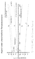
- the diagram shown in the drawing shows the temperature-dependent fault tolerance of two temperature sensors, not shown in detail, of a motor vehicle.
- the first temperature sensor is used to determine the cooling water temperature of an internal combustion engine. It covers a temperature range from around -30 ° C to 150 ° C. Its fault tolerance is a uniform +/- 2.5 K over the entire measuring range. This temperature range including the fault tolerance band is designated by I.
- a second temperature sensor is used to determine the exhaust gas temperature of the internal combustion engine. It has a temperature range from -50 ° C to about 1000 ° C. Its fault tolerance is temperature-dependent and increases with increasing temperature. Furthermore, the tolerance band is significantly larger than in the case of the first temperature sensor. At 0 ° C it ranges from -30 to + 30 ° C, i.e. the temperature sensors of this type used at 0 ° C actually output a temperature value that is between -30 ° and + 30 ° C. The entire temperature tolerance band for the second temperature sensor is designated II.
- the two sensor signals are compared.
- the weighted average of the temperature values supplied by the two temperature sensors is determined.
- the prerequisite for the adjustment is given after the internal combustion engine has been idle for several hours.
- the actual temperature is, for example, 20 ° C, the corresponding value is marked with an x on the temperature scale.
- the temperature error of the second temperature sensor is, for example, 25 ° C. at an actual temperature of 20 ° C.
- the temperature value supplied by the first temperature sensor and taking into account the maximum possible error for this value (+/- 2.5 °)
- the temperature value supplied by the second temperature sensor here is significantly higher than the actual temperature value.
- the temperature value, how it is supplied by the second temperature sensor is therefore adapted. For this purpose, the weighted arithmetic mean of the two temperature values is determined.
- the weighting factor for the temperature value, as supplied by the first temperature sensor, is much higher due to the small maximum error deviation, for example equal to 0.95, while the temperature value of the second temperature sensor is then only weighted with the factor of 0.05.
- the result is a mathematically determined temperature value of, for example, 22 ° for the cooling water and the exhaust gas temperature.
- the tolerance band of the second temperature sensor can be limited to the range which is limited by two lines g1 and g1 'running in mirror image to the temperature scale. These lines run parallel to the specified lines g0 and g0 ', which limit the tolerance band II.
- the weighted arithmetic mean is taken for the starting temperature, here absolutely 20 ° C, from the temperature values T1 and T2 of the temperatures determined by the two temperature sensors.
- the calculated absolute temperature T ar determines.
- the temperature signal measured at an absolute 1000 ° C, here from 1038 ° C, is corrected downwards by the value of x 23 °. This results in the calculated temperature for the second temperature sensor of 1015 ° C.
- the last-mentioned operation presupposes that the temperature response of the temperature sensor is constant over the entire measuring range. If this is not the case, but is dependent on the absolute temperature - a linear dependence is shown in the diagram - this temperature dependency is also taken into account and the difference value of 23 ° C, which is assumed to be 20 ° C, is corrected up or down according to the absolute temperature . This correction can also be carried out with the aid of a table from which a computer takes the correcting value that is valid at the time and applies it to determine the valid temperature.
- the display shows an error tolerance of an additional 12 ° C, which leads to a corrected temperature value of 1003 ° C at an actual 1000 ° C.
Landscapes
- Physics & Mathematics (AREA)
- General Physics & Mathematics (AREA)
- Combined Controls Of Internal Combustion Engines (AREA)
Abstract
Description
Die Erfindung bezieht sich auf ein Verfahren nach dem Oberbegriff des Patentanspruchs 1.The invention relates to a method according to the preamble of patent claim 1.
Innerhalb eines Systems mit Verschiedenen Objekten werden punktuell Temperaturen der Objekte bestimmt. Auch kann die Temperatur eines Objekts durch mehrere Temperaturfühler bestimmt werden. Beispielsweise wird bei einem Kraftfahrzeug eine Vielzahl von Temperaturen gemessen Bei den Objekten handelt es sich beispielsweise um die verschiedenen Medien wie Ansaugluft, Abgastemperatur vor und nach dem Durchlaufen eines Katalysators, die Kühlwassertemperatur oder auch die Temperatur an definierten Stellen der Brennkraftmaschine. Jeder dieser Temperaturfühler besitzt eine meist bauartbedingte Toleranz, die das Ergebnis einer dem Temperaturfühler zugeordneten elektronischen Auswerte- und Verarbeitungseinheit beeinflußt. So geht beispielsweise die Abweichung eines Temperaturfühlers für das Kühlwasser in das Signal für die Einspritzmenge bzw. den Zündzeitpunkt der Brennkraftmaschine des Kraftfahrzeugs ein.Within a system with different objects, temperatures of the objects are determined selectively. The temperature of an object can also be determined by several temperature sensors. For example, a multitude of temperatures are measured in a motor vehicle. The objects are, for example, the various media such as intake air, exhaust gas temperature before and after passing through a catalytic converter, the cooling water temperature or the temperature at defined points on the internal combustion engine. Each of these temperature sensors has a tolerance, which is mostly due to the design, which influences the result of an electronic evaluation and processing unit assigned to the temperature sensor. For example, the deviation of a temperature sensor for the cooling water is included in the signal for the injection quantity or the ignition timing of the internal combustion engine of the motor vehicle.
Da die Temperaturfühler häufig auch einen großen Temperaturbereich abdecken, beispielsweise erreicht die Abgastemperatur Werte um die 1000 °C, hängt die Fehlertoleranz auch von der jeweils vorliegenden tatsächlichen Temperatur ab und ist meist mit steigender Temperatur zunehmend. Gerade bei einem großen Temperaturbereich zeigt sich, daß die Fehlertoleranz absolut auch erheblich ist mit der Folge entsprechender Unsicherheiten und Toleranzen des davon abhängigen Signals. Im Zuge verschärfter Abgasbestimmungen ergibt sich damit aber ein zunehmendes Problem.Since the temperature sensors often also cover a large temperature range, for example the exhaust gas temperature reaches values around 1000 ° C, the fault tolerance also depends on the actual temperature in each case and usually increases with increasing temperature. Especially in the case of a large temperature range, it can be seen that the error tolerance is absolutely also considerable, with the consequence of corresponding uncertainties and tolerances of the signal dependent thereon. In the course of stricter exhaust gas regulations, however, there is an increasing problem.
Zur Einhaltung der Abgasbestimmungen könnten verschiedene Wege eingeschlagen werden, die jedoch im Ergebnis unbefriedigend sind. So könnte beispielsweise ein Zusätzlicher Regelungsaufwand betrieben werden, um das von der Auswerte und Verarbeitungseinheit gelieferte Signal so zu verbessern, daß die Vorgaben für das Immissionsverhalten eingehalten werden. Ein anderer Weg wäre, die Temperaturfühler selbst möglichst toleranzfrei zu machen. Dies aber ist mit erheblichen Kosten verbunden. Erfahrungsgemäß steigen die Kosten für Temperaturfühler mit sinkender Fehlertoleranz unverhältnismäßig hoch an.Various ways could be taken to comply with the exhaust gas regulations, but the result is unsatisfactory. For example, an additional regulation effort could be carried out in order to improve the signal supplied by the evaluation and processing unit in such a way that the requirements for the immission behavior are met. Another way would be to make the temperature sensors themselves as tolerance-free as possible. But this is associated with considerable costs. Experience has shown that the cost of temperature sensors increases disproportionately with decreasing fault tolerance.
Der Erfindung liegt die Aufgabe zugrunde, ein Verfahren der eingangs genannten Art zu schaffen, das mit geringem Aufwand eine hohe Genauigkeit für die Temperaturbestimmung eines Objekt liefert.The invention has for its object to provide a method of the type mentioned, which provides high accuracy for the temperature determination of an object with little effort.
Die Erfindung löst diese Aufgabe durch die kennzeichnenden Merkmale des Patentanspruchs 1.The invention solves this problem by the characterizing features of patent claim 1.
Die Erfindung setzt zum einen voraus, daß die mit beiden Temperaturfühler bestimmten Temperaturen zumindest annähernd gleich sind. Dies ist dann der Fall, wenn das Objekt über einen längeren Zeitraum hinweg ohne gesonderte Temperaturbeaufschlagung ist und das thermische Gleichgewicht mit der Umgebung vorliegt. Ein Beispiel hierfür ist eine mehrstündige Ruhezeit eines Kraftfahrzeugs, während der die Komponenten des Kraftfahrzeugs zumindest annähernd auf Umgebungstemperatur kommen. Ist dies der Fall, so sind fehlertoleranzfreie Temperaturfühler vorausgesetzt, die von beiden Temperaturfühlern gemessenen Temperaturen auch dann gleich, wenn die beiden Temperaturfühler unterschiedlichen Objekten zugeordnet sind. Die Temperatur im Ansaugtrakt der Brennkraftmaschine ist gleich der des Kühlwassers bzw. der im Abgastrakt, sofern eine entsprechend lange, beispielsweise mehrstündige Betriebspause der Brennkraftmaschine vorhergeht.The invention requires, on the one hand, that the temperatures determined with both temperature sensors are at least approximately the same. This is the case if the object is without separate temperature exposure over a longer period of time and the thermal equilibrium with the environment is present. An example of this is a motor vehicle's rest period of several hours, during which the components of the motor vehicle come at least approximately to ambient temperature. Is that the case, fault-free temperature sensors are required, the temperatures measured by both temperature sensors are the same even if the two temperature sensors are assigned to different objects. The temperature in the intake tract of the internal combustion engine is equal to that of the cooling water or that in the exhaust tract, provided that the internal combustion engine has been in operation for a correspondingly long time, for example several hours.
Als weiterer Schritt wird bei der Erfindung eine Mittelwertbildung vorgenommen. Es kann sich dabei um die Bildung des arithmetischen oder auch des geometrischen Modells der von den Temperaturfühlern gelieferten Temperaturen handeln.As a further step, averaging is carried out in the invention. This can involve the formation of the arithmetic or else the geometric model of the temperatures supplied by the temperature sensors.
Als weiterer Verfahrensschritt wird das Ausgangssignal der beiden Temperaturfühler korrigiert. Den Ausgangssignalen beider Temperaturfühler wird die gemittelte Temperatur zugeordnet.As a further process step, the output signal of the two temperature sensors is corrected. The average temperature is assigned to the output signals of both temperature sensors.
Gegenüber den genannten Formen der Mittelwertbildung ergibt sich eine Verbesserung der Erfindung, wenn der Mittelwertbildung entsprechend der Fehlertoleranz der Temperaturfühler erfolgt. Es sei ein Temperaturfühler mit kleiner Fehlertoleranz und ein Temperaturfühler mit großer Fehlertoleranz angenommen. Durch die Berücksichtigung der Fehlertoleranzen der beiden Temperaturfühler wird das Ausgangssignal des Temperaturfühlers mit geringer Fehlertoleranz stärker als das des Temperaturfühlers mit großer Fehlertoleranz gewichtet. Es wird somit das gewichtete (auch gewogene genannte) arithmetische Mittel der beiden Temperaturen bestimmt. Der Wichtungsfaktor ist umso größer, je kleiner die Fehlertoleranz des jeweiligen Temperaturfühlers ist. Damit wird einerseits die große Fehlertoleranz des einen Temperaturfühlers deutlich eingeschränkt. Andererseits macht sich die Fehlertoleranz dieses Temperaturfühlers für das Ausgangssignal des Temperaturfühlers mit kleiner Fehlertoleranz nicht wesentlich bemerkbar.Compared to the above-mentioned forms of averaging, the invention improves if the averaging takes place in accordance with the fault tolerance of the temperature sensors. A temperature sensor with a small fault tolerance and a temperature sensor with a large fault tolerance are assumed. By taking into account the fault tolerances of the two temperature sensors, the output signal of the temperature sensor with a low fault tolerance is weighted more strongly than that of the temperature sensor with a large fault tolerance. The weighted (also referred to as weighed) arithmetic mean of the two temperatures is thus determined. The smaller the error tolerance of the respective temperature sensor, the greater the weighting factor. On the one hand, this greatly limits the large fault tolerance of one temperature sensor. On the other hand, the fault tolerance increases this temperature sensor for the output signal of the temperature sensor with small fault tolerance is not significantly noticeable.
Wie bereits eingangs ausgeführt, hängt die Fehlertoleranz mitunter auch von der jeweils vorliegenden Temperatur ab. Entsprechend sieht eine weitere Verbesserung der Erfindung vor, die Mittelwertbildung abhängig von der gemessenen Temperatur vorzunehmen. Damit wird auch die temperaturabhängige Änderung der Fehlertoleranz der Temperaturfühler berücksichtigt und beispielsweise im Falle der Bildung des gewichteten Mittels der Wichtungsfaktor temperaturabhängig angenommen.As already mentioned at the beginning, the fault tolerance sometimes also depends on the temperature at hand. Accordingly, a further improvement of the invention provides for averaging to take place as a function of the measured temperature. The temperature-dependent change in the fault tolerance of the temperature sensors is thus also taken into account and, for example, the weighting factor is assumed to be temperature-dependent if the weighted average is formed.
Schließlich kann auch mit Hilfe eines Rechners die Fehlerkorrektur der Temperaturfühler vorgenommen werden. Mit Hilfe von Fehlertoleranzen, die aus einer Tabelle entnommen werden, wird mit Hilfe des Rechners der Abgleich der von beiden Temperaturfühlern gemessenen Temperaturen vorgenommen.Finally, the error correction of the temperature sensors can also be carried out with the help of a computer. With the help of error tolerances, which are taken from a table, the computer is used to compare the temperatures measured by both temperature sensors.
Anhand eines Diagramms ist die Erfindung weiter erläutert.The invention is further explained on the basis of a diagram.
Das in der Zeichnung dargestellte Diagramm zeigt die temperaturabhängige Fehlertoleranz zweier nicht im einzelnen dargestellten Temperaturfühler eines Kraftfahrzeugs. Der erste Temperaturfühler dient dazu, die Kühlwassertemperatur einer Brennkraftmaschine zu bestimmen. Er deckt einen Temperaturbereich von etwa -30°C bis 150°C ab. Seine Fehlertoleranz beträgt über den gesamten Meßbereich einheitlich +/- 2,5 K. Dieser Temperaturbereich einschließlich des Fehlertoleranzbands ist mit I bezeichnet.The diagram shown in the drawing shows the temperature-dependent fault tolerance of two temperature sensors, not shown in detail, of a motor vehicle. The first temperature sensor is used to determine the cooling water temperature of an internal combustion engine. It covers a temperature range from around -30 ° C to 150 ° C. Its fault tolerance is a uniform +/- 2.5 K over the entire measuring range. This temperature range including the fault tolerance band is designated by I.
Ein zweiter Temperaturfühler dient dazu, die Abgastemperatur der Brennkraftmaschine zu bestimmen. Er besitzt einen Temperaturbereich von -50°C bis etwa 1000°C. Seine Fehlertoleranz ist temperaturabhängig und mit steigender Temperatur steigend. Ferner ist das Toleranzband wesentlich größer als im Falle des ersten Temperaturfühlers. Bei 0°C reicht es von -30 bis +30°C, d.h. die verwendeten Temperaturfühler dieses Typs geben bei tatsächlich 0°C einen Temperaturwert aus, der zwischen -30° und +30°C liegt. Das gesamte Temperaturtoleranzband für den zweiten Temperaturfühler ist mit II bezeichnet.A second temperature sensor is used to determine the exhaust gas temperature of the internal combustion engine. It has a temperature range from -50 ° C to about 1000 ° C. Its fault tolerance is temperature-dependent and increases with increasing temperature. Furthermore, the tolerance band is significantly larger than in the case of the first temperature sensor. At 0 ° C it ranges from -30 to + 30 ° C, i.e. the temperature sensors of this type used at 0 ° C actually output a temperature value that is between -30 ° and + 30 ° C. The entire temperature tolerance band for the second temperature sensor is designated II.
Erfindungsgemäß erfolgt dann, wenn die mit den beiden Temperaturfühlern gemessene Temperatur tatsächlich zumindest annähernd gleich ist, ein Abgleich der beiden Sensorsignale. Hierzu wird das gewichtete Mittel der von den beiden Temperaturfühlern gelieferten Temperaturwerte bestimmt. Die Voraussetzung für den Abgleich ist nach einem mehrstündigen Stillstand der Brennkraftmaschine gegeben. Die tatsächliche Temperatur betrage beispielsweise 20°C, der entsprechende Wert ist auf der Temperaturskala mit einem x gekennzeichnet. Entsprechend dem angegebenen Toleranzband entspricht das Temperatursignal für den ersten Temperaturfühler einer Temperatur von beispielsweise 20+1=21°C.According to the invention, when the temperature measured with the two temperature sensors is actually at least approximately the same, the two sensor signals are compared. For this purpose, the weighted average of the temperature values supplied by the two temperature sensors is determined. The prerequisite for the adjustment is given after the internal combustion engine has been idle for several hours. The actual temperature is, for example, 20 ° C, the corresponding value is marked with an x on the temperature scale. According to the specified tolerance band, the temperature signal for the first temperature sensor corresponds to a temperature of, for example, 20 + 1 = 21 ° C.
Der Temperaturfehler des zweiten Temperaturfühlers beträgt bei 20°C tatsächlicher Temperatur beispielsweise 25°C. Das Ausgangssignal dieses Temperaturfühlers entspricht daher einer Temperatur von 20+25=45°C bei absolut exakter Temperatur von 20°C. Aufgrund des vom ersten Temperaturfühlers gelieferten Temperaturwerts und unter Berücksichtigung des für diesen Wert maximal möglichen Fehler (+/- 2,5°) ergibt sich, daß der vom zweiten Temperaturfühler gelieferte Temperaturwert hier deutlich höher als der tatsächliche Temperaturwert ist. Der Temperaturwert, wie er vom zweiten Temperaturfühler geliefert wird, wird daher angepaßt. Hierzu wird das gewichtete arithmetische Mittel der beiden Temperaturwerte bestimmt. Dabei ist der Wichtungsfaktor für den Temperaturwert, wie er vom ersten Temperaturfühler geliefert wird, aufgrund der geringen maximalen Fehlerabweichung wesentlich höher, beispielsweise gleich 0,95, während der Temperaturwert des zweiten Temperaturfühlers dann nur noch mit dem Faktor von 0,05 gewichtet wird. Es ergibt sich somit ein rechnerisch ermittelter Temperaturwert von beispielsweise 22° übereinstimmend für das Kühlwasser und die Abgastemperatur.The temperature error of the second temperature sensor is, for example, 25 ° C. at an actual temperature of 20 ° C. The output signal of this temperature sensor therefore corresponds to a temperature of 20 + 25 = 45 ° C at an absolutely exact temperature of 20 ° C. Based on the temperature value supplied by the first temperature sensor and taking into account the maximum possible error for this value (+/- 2.5 °), it follows that the temperature value supplied by the second temperature sensor here is significantly higher than the actual temperature value. The temperature value, how it is supplied by the second temperature sensor is therefore adapted. For this purpose, the weighted arithmetic mean of the two temperature values is determined. The weighting factor for the temperature value, as supplied by the first temperature sensor, is much higher due to the small maximum error deviation, for example equal to 0.95, while the temperature value of the second temperature sensor is then only weighted with the factor of 0.05. The result is a mathematically determined temperature value of, for example, 22 ° for the cooling water and the exhaust gas temperature.
Mit diesem Ausgangswert von 22°C ermittelter rechnerischer Temperatur (bei tatsächlich absolut 20°C) läßt sich auch für Temperaturwerte, die oberhalb des mit dem ersten Temperaturfühler bestimmbaren Temperaturwerts liegen, eine Verringerung des Meßfehlers erzielen. Bedingt durch die vorgegebene temperaturabhängige Verbreiterung des Fehlertoleranzbands II läßt sich das Toleranzband des zweiten Temperaturfühlers auf den Bereich eingrenzen, der durch zwei spiegelbildlich zur Temperaturskala verlaufende Geraden g1 und g1' begrenzt ist. Diese Geraden verlaufen parallel zu den vorgegebenen Geraden g0 und g0', die das Toleranzband II begrenzen. Im angenommenen Fall einer Abweichung des gemessenen Temperaturwerts um 25°C bei 20°C ergibt sich somit bei beispielsweise 1000 °C absolut ein vermeintlicher Temperaturwert von 1038°C, der in einen entsprechenden Temperaturwert von 1005°C übergeführt wird. Zur Verdeutlichung:With this starting value of 22 ° C calculated temperature (at actually absolutely 20 ° C), a reduction in the measurement error can also be achieved for temperature values that are above the temperature value that can be determined with the first temperature sensor. Due to the predetermined temperature-dependent broadening of the fault tolerance band II, the tolerance band of the second temperature sensor can be limited to the range which is limited by two lines g1 and g1 'running in mirror image to the temperature scale. These lines run parallel to the specified lines g0 and g0 ', which limit the tolerance band II. In the assumed case of a deviation of the measured temperature value by 25 ° C at 20 ° C, this results in an assumed temperature value of 1038 ° C in absolute terms, for example 1000 ° C, which is converted into a corresponding temperature value of 1005 ° C. For clarification:
In einem ersten Schritt wird für die Ausgangstemperatur, hier absolut mit 20°C angenommen, aus den Temperaturwerten T1 und T2 der von den beiden Temperaturfühler bestimmten Temperaturen das gewichtete arithmetische Mittel, die rechnerisch bestimmte absolute Temperatur Tar bestimmt.In a first step, the weighted arithmetic mean is taken for the starting temperature, here absolutely 20 ° C, from the temperature values T1 and T2 of the temperatures determined by the two temperature sensors. the calculated absolute temperature T ar determines.
In einem zweiten Schritt wird die Abweichung x des vom zweiten Meßfühler gelieferten Temperatursignals, hier =23° bestimmt. Das bei absolut 1000 °C gemessene Temperatursignal, hier von 1038 °C wird um den Wert von x=23° nach unten korrigiert. Daraus ergibt sich die rechnerisch bestimmte Temperatur für den zweiten Temperaturfühler von 1015°C.In a second step, the deviation x of the temperature signal supplied by the second sensor, here = 23 °, is determined. The temperature signal measured at an absolute 1000 ° C, here from 1038 ° C, is corrected downwards by the value of x = 23 °. This results in the calculated temperature for the second temperature sensor of 1015 ° C.
Die zuletzt genannte Operation setzt voraus, daß der Temperaturgang des Temperaturfühlers über den gesamten Meßbereich konstant ist. Sofern dies nicht der Fall ist, sondern er von der Absoluttemperatur abhängig ist -im Diagramm ist eine lineare Abhängigkeit gezeigt- wird diese Temperaturabhängigkeit ebenfalls berücksichtigt und der bei angenommen 20°C bestehende Differenzwert von 23°C entsprechend der absoluten Temperatur nach oben oder unten korrigiert. Diese Korrektur kann auch mit Hilfe einer Tabelle vorgenommen werden, aus der ein Rechner den jeweils gültigen Korrekturvert entnimmt und zur Bestimmung der gültigen Temperatur in Ansatz bringt. In der Darstellung ergibt sich eine Fehlertoleranz von zusätzlich 12°C, was zu einem korrigierten Temperaturwert von 1003°C bei tatsächlicher 1000°C führt.The last-mentioned operation presupposes that the temperature response of the temperature sensor is constant over the entire measuring range. If this is not the case, but is dependent on the absolute temperature - a linear dependence is shown in the diagram - this temperature dependency is also taken into account and the difference value of 23 ° C, which is assumed to be 20 ° C, is corrected up or down according to the absolute temperature . This correction can also be carried out with the aid of a table from which a computer takes the correcting value that is valid at the time and applies it to determine the valid temperature. The display shows an error tolerance of an additional 12 ° C, which leads to a corrected temperature value of 1003 ° C at an actual 1000 ° C.
Damit ergibt sich durch Berücksichtigung unterschiedlicher Temperaturfühler eine deutliche Verringerung der von diesen gelieferten Temperaturfehler. Voraussetzung hierfür ist die Annahme, daß die mit den Temperaturfühlern bestimmte Temperatur absolut zumindest annähernd gleich ist sowie die Kenntnis der Fehlertoleranzen der jeweiligen Temperaturfühler. Diese können, wie dargestellt, von unterschiedlicher Bauart sein und unterschiedlichen Objekten Zugeordnet sein. Sie können aber auch von gleicher Bauart sein und unterschiedlichen Objekten oder demselben Objekt zugeordnet sein. Sie sitzen dann an der gleichen Stelle oder unterschiedlichen Stellen des Objekts.By taking into account different temperature sensors, this results in a significant reduction in the temperature errors supplied by them. The prerequisite for this is the assumption that the temperature determined with the temperature sensors is absolutely at least approximately the same as well as the knowledge of the fault tolerances of the respective temperature sensors. As shown, these can be of different designs and can be assigned to different objects. But you can also of the same Be of type and assigned to different objects or the same object. You then sit in the same place or different places on the object.
Claims (4)
Applications Claiming Priority (2)
| Application Number | Priority Date | Filing Date | Title |
|---|---|---|---|
| DE19934337272 DE4337272A1 (en) | 1993-11-02 | 1993-11-02 | Method for determining the temperature of an object |
| DE4337272 | 1993-11-02 |
Publications (1)
| Publication Number | Publication Date |
|---|---|
| EP0651237A1 true EP0651237A1 (en) | 1995-05-03 |
Family
ID=6501547
Family Applications (1)
| Application Number | Title | Priority Date | Filing Date |
|---|---|---|---|
| EP94115848A Withdrawn EP0651237A1 (en) | 1993-11-02 | 1994-10-07 | Method for determining the temperature of an object |
Country Status (2)
| Country | Link |
|---|---|
| EP (1) | EP0651237A1 (en) |
| DE (1) | DE4337272A1 (en) |
Cited By (7)
| Publication number | Priority date | Publication date | Assignee | Title |
|---|---|---|---|---|
| EP0816816A1 (en) * | 1996-06-27 | 1998-01-07 | Bayerische Motoren Werke Aktiengesellschaft, Patentabteilung AJ-3 | Method for model-supported simulation of the temperature of the cooling means in a motor vehicle |
| EP0823620A1 (en) * | 1996-08-09 | 1998-02-11 | Schott Glaswerke | Method for calibrating temperature measuring resistances on substrates of glass, glass-ceramic or similar |
| GB2343754A (en) * | 1998-11-13 | 2000-05-17 | Ford Motor Co | Sensor malfunction diagnosis |
| FR2796460A1 (en) * | 1999-07-16 | 2001-01-19 | Valeo Electronique | Temperature sensor unit for vehicle cabin is fitted to air conditioning control console has compensation for unit temperature |
| WO2001035065A1 (en) * | 1999-11-10 | 2001-05-17 | Robert Bosch Gmbh | Method for testing the performance and/or adjustment of an exhaust gas temperature sensor |
| EP1102048A1 (en) * | 1999-11-19 | 2001-05-23 | Heraeus Electro-Nite International N.V. | Method for calibrating a temperature sensor |
| US6644850B2 (en) | 2001-05-22 | 2003-11-11 | Bayerische Motoren Werke Aktiengesellschaft | Temperature sensing device for an internal-combustion engine |
Citations (6)
| Publication number | Priority date | Publication date | Assignee | Title |
|---|---|---|---|---|
| DE3145333A1 (en) * | 1981-11-14 | 1983-05-26 | Brown, Boveri & Cie Ag, 6800 Mannheim | Method for testing temperature sensors |
| JPS6031029A (en) * | 1983-08-01 | 1985-02-16 | Yamatake Honeywell Co Ltd | Method of measuring amount of heat accumulation |
| JPS60164240A (en) * | 1984-02-06 | 1985-08-27 | Nippon Denso Co Ltd | Heater control device for oxygen concentration sensor |
| US4926364A (en) * | 1988-07-25 | 1990-05-15 | Westinghouse Electric Corp. | Method and apparatus for determining weighted average of process variable |
| US5214267A (en) * | 1989-12-15 | 1993-05-25 | Toyota Jidosha Kabushiki Kaisha | Apparatus for controlling heater for heating oxygen sensor |
| US5253190A (en) * | 1992-07-01 | 1993-10-12 | Westinghouse Electric Corp. | Weighted temperature measurement using multiple sensors |
Family Cites Families (5)
| Publication number | Priority date | Publication date | Assignee | Title |
|---|---|---|---|---|
| GB1291827A (en) * | 1968-10-28 | 1972-10-04 | Rosemount Eng Co Ltd | Improvements in or relating to temperature measuring apparatus |
| US4340886A (en) * | 1978-07-03 | 1982-07-20 | Dickey-John Corporation | Bearing and motor temperature monitor |
| US4863279A (en) * | 1988-02-22 | 1989-09-05 | Morris L. Markel | Operative temperature sensing system |
| DE4024863A1 (en) * | 1990-08-04 | 1992-02-06 | Werner & Pfleiderer | METHOD FOR MEASURING THE TEMPERATURE OF THE MATERIAL IN A MIXING CHAMBER OF A KNEADER |
| DE4110671A1 (en) * | 1991-04-03 | 1992-10-08 | Jenoptik Jena Gmbh | METHOD AND ARRANGEMENT FOR TEMPERATURE CONTROL OF A DEVICE |
-
1993
- 1993-11-02 DE DE19934337272 patent/DE4337272A1/en not_active Withdrawn
-
1994
- 1994-10-07 EP EP94115848A patent/EP0651237A1/en not_active Withdrawn
Patent Citations (6)
| Publication number | Priority date | Publication date | Assignee | Title |
|---|---|---|---|---|
| DE3145333A1 (en) * | 1981-11-14 | 1983-05-26 | Brown, Boveri & Cie Ag, 6800 Mannheim | Method for testing temperature sensors |
| JPS6031029A (en) * | 1983-08-01 | 1985-02-16 | Yamatake Honeywell Co Ltd | Method of measuring amount of heat accumulation |
| JPS60164240A (en) * | 1984-02-06 | 1985-08-27 | Nippon Denso Co Ltd | Heater control device for oxygen concentration sensor |
| US4926364A (en) * | 1988-07-25 | 1990-05-15 | Westinghouse Electric Corp. | Method and apparatus for determining weighted average of process variable |
| US5214267A (en) * | 1989-12-15 | 1993-05-25 | Toyota Jidosha Kabushiki Kaisha | Apparatus for controlling heater for heating oxygen sensor |
| US5253190A (en) * | 1992-07-01 | 1993-10-12 | Westinghouse Electric Corp. | Weighted temperature measurement using multiple sensors |
Non-Patent Citations (3)
| Title |
|---|
| ANONYMOUS: "AUTOMATIC AUTOMOTIVE VEHICLE TEMPERATURE VERIFICATION", IBM TECHNICAL DISCLOSURE BULLETIN, vol. 29, no. 8, January 1987 (1987-01-01), NEW YORK US, pages 3513 - 3515 * |
| HELEN HOERSCH (EDITOR): "MANUAL ON THE USE OF THERMOCOUPLES IN TEMPERATURE MEASUREMENT", 1981, ASTM, PHILADELPHIA, -1981 * |
| PATENT ABSTRACTS OF JAPAN vol. 10, no. 7 (P - 419) 11 January 1986 (1986-01-11) * |
Cited By (10)
| Publication number | Priority date | Publication date | Assignee | Title |
|---|---|---|---|---|
| EP0816816A1 (en) * | 1996-06-27 | 1998-01-07 | Bayerische Motoren Werke Aktiengesellschaft, Patentabteilung AJ-3 | Method for model-supported simulation of the temperature of the cooling means in a motor vehicle |
| EP0823620A1 (en) * | 1996-08-09 | 1998-02-11 | Schott Glaswerke | Method for calibrating temperature measuring resistances on substrates of glass, glass-ceramic or similar |
| US6155711A (en) * | 1996-08-09 | 2000-12-05 | Schott Glas | Method of calibrating temperature-measuring resistors on a glass, glass-ceramic, or similar substrate |
| GB2343754A (en) * | 1998-11-13 | 2000-05-17 | Ford Motor Co | Sensor malfunction diagnosis |
| US6091324A (en) * | 1998-11-13 | 2000-07-18 | Ford Motor Company | Comparing sensor outputs to distinguish between sensor faults and extreme temperature conditions |
| GB2343754B (en) * | 1998-11-13 | 2003-03-26 | Ford Motor Co | Comparing sensor outputs to distinguish between sensor faults and extreme temperature conditions |
| FR2796460A1 (en) * | 1999-07-16 | 2001-01-19 | Valeo Electronique | Temperature sensor unit for vehicle cabin is fitted to air conditioning control console has compensation for unit temperature |
| WO2001035065A1 (en) * | 1999-11-10 | 2001-05-17 | Robert Bosch Gmbh | Method for testing the performance and/or adjustment of an exhaust gas temperature sensor |
| EP1102048A1 (en) * | 1999-11-19 | 2001-05-23 | Heraeus Electro-Nite International N.V. | Method for calibrating a temperature sensor |
| US6644850B2 (en) | 2001-05-22 | 2003-11-11 | Bayerische Motoren Werke Aktiengesellschaft | Temperature sensing device for an internal-combustion engine |
Also Published As
| Publication number | Publication date |
|---|---|
| DE4337272A1 (en) | 1995-05-04 |
Similar Documents
| Publication | Publication Date | Title |
|---|---|---|
| DE4039876B4 (en) | Device for controlling the air-fuel ratio for an engine | |
| DE69525914T2 (en) | Position detection for vehicles | |
| DE69617513T2 (en) | Nonlinear dynamic transformation to correct a crankshaft acceleration subject to torsional vibrations | |
| DE4120388C2 (en) | Temperature detection method | |
| AT4801U2 (en) | METHOD AND DEVICE FOR PROVIDING A CRANK ANGLE-BASED SIGNAL PROCESS | |
| EP0929794B1 (en) | Method and device for correcting margins of error of an indicating wheel | |
| DE19844994A1 (en) | Continuous lambda probe diagnosis method | |
| DE60122803T2 (en) | Knock detection in an internal combustion engine with ion current maximum value correction | |
| DE102005042794B4 (en) | Automatic calibration procedure for a misfire detection system of an engine | |
| DE68909496T2 (en) | Electrical control device for motor vehicles and compensation method for the time delay of measurement data. | |
| DE3546168A1 (en) | ARRANGEMENT FOR REGULATING THE IGNITION TIMING OF AN INTERNAL COMBUSTION ENGINE | |
| DE19652026A1 (en) | Air amount measuring system for measuring suction air amount flowing in internal combustion engine | |
| DE3513086C2 (en) | ||
| DE3721010A1 (en) | METHOD AND DEVICE FOR DETECTING THE MAXIMUM CYLINDER PRESSURE ANGLE IN AN INTERNAL COMBUSTION ENGINE | |
| DE4238807A1 (en) | IC engine exhaust gas catalyser monitoring system - uses cross-correlation function for signals from oxygen@ sensors inserted in exhaust line before and after catalyser | |
| EP1715165A2 (en) | Apparatus and method for fault diagnosis in a combustion engine | |
| EP0651237A1 (en) | Method for determining the temperature of an object | |
| DE69932523T2 (en) | METHOD AND SYSTEM FOR DETECTING COMBUSTION TOOLS USING A SYNCHRONOUS CORRECTION | |
| DE69705150T2 (en) | Method for diagnosing the efficiency of a stochiometric exhaust gas sensor arranged downstream of a catalytic converter | |
| DE4334068A1 (en) | Engine misfire detection method | |
| DE102008052245A1 (en) | Method for determining crank shaft torsional optimal operating method of internal combustion engine, involves determining speed signals of crank shaft under operating condition of internal combustion engine | |
| DE102016006327A1 (en) | Method and device for adapting an exhaust gas recirculation valve | |
| DE3819016A1 (en) | SYSTEM FOR DETECTING ABNORMAL OPERATION OF AN INTERNAL COMBUSTION ENGINE | |
| DE3447629A1 (en) | SIGNAL PROCESSING SYSTEM FOR A MOTOR VEHICLE ACCELERATION PROBE | |
| WO1997022786A2 (en) | Process for detecting cyclical fluctuations in combustion in an internal combustion engine |
Legal Events
| Date | Code | Title | Description |
|---|---|---|---|
| PUAI | Public reference made under article 153(3) epc to a published international application that has entered the european phase |
Free format text: ORIGINAL CODE: 0009012 |
|
| AK | Designated contracting states |
Kind code of ref document: A1 Designated state(s): DE FR GB IT |
|
| 17P | Request for examination filed |
Effective date: 19950518 |
|
| 17Q | First examination report despatched |
Effective date: 19980803 |
|
| GRAG | Despatch of communication of intention to grant |
Free format text: ORIGINAL CODE: EPIDOS AGRA |
|
| GRAG | Despatch of communication of intention to grant |
Free format text: ORIGINAL CODE: EPIDOS AGRA |
|
| GRAH | Despatch of communication of intention to grant a patent |
Free format text: ORIGINAL CODE: EPIDOS IGRA |
|
| GRAH | Despatch of communication of intention to grant a patent |
Free format text: ORIGINAL CODE: EPIDOS IGRA |
|
| STAA | Information on the status of an ep patent application or granted ep patent |
Free format text: STATUS: THE APPLICATION IS DEEMED TO BE WITHDRAWN |
|
| 18D | Application deemed to be withdrawn |
Effective date: 20020501 |