EP0650557B1 - Moteur a plasma a derive fermee d'electrons - Google Patents
Moteur a plasma a derive fermee d'electrons Download PDFInfo
- Publication number
- EP0650557B1 EP0650557B1 EP92919481A EP92919481A EP0650557B1 EP 0650557 B1 EP0650557 B1 EP 0650557B1 EP 92919481 A EP92919481 A EP 92919481A EP 92919481 A EP92919481 A EP 92919481A EP 0650557 B1 EP0650557 B1 EP 0650557B1
- Authority
- EP
- European Patent Office
- Prior art keywords
- buffer chamber
- annular
- anode
- accelerator according
- plasma accelerator
- Prior art date
- Legal status (The legal status is an assumption and is not a legal conclusion. Google has not performed a legal analysis and makes no representation as to the accuracy of the status listed.)
- Expired - Lifetime
Links
- 230000005291 magnetic effect Effects 0.000 claims abstract description 53
- 230000001133 acceleration Effects 0.000 claims abstract description 31
- 239000011810 insulating material Substances 0.000 claims abstract description 17
- 238000011144 upstream manufacturing Methods 0.000 claims abstract description 10
- 230000006698 induction Effects 0.000 claims abstract description 9
- 229910052751 metal Inorganic materials 0.000 claims description 7
- 239000002184 metal Substances 0.000 claims description 7
- 230000002093 peripheral effect Effects 0.000 claims description 6
- 239000000696 magnetic material Substances 0.000 claims description 3
- 230000007704 transition Effects 0.000 claims description 3
- 238000010292 electrical insulation Methods 0.000 claims 3
- 150000002500 ions Chemical class 0.000 description 15
- 239000007789 gas Substances 0.000 description 12
- 229910052724 xenon Inorganic materials 0.000 description 12
- FHNFHKCVQCLJFQ-UHFFFAOYSA-N xenon atom Chemical compound [Xe] FHNFHKCVQCLJFQ-UHFFFAOYSA-N 0.000 description 12
- 239000003380 propellant Substances 0.000 description 9
- PNEYBMLMFCGWSK-UHFFFAOYSA-N aluminium oxide Inorganic materials [O-2].[O-2].[O-2].[Al+3].[Al+3] PNEYBMLMFCGWSK-UHFFFAOYSA-N 0.000 description 8
- 239000000919 ceramic Substances 0.000 description 8
- 230000005855 radiation Effects 0.000 description 7
- 229910052593 corundum Inorganic materials 0.000 description 6
- 229910001845 yogo sapphire Inorganic materials 0.000 description 6
- 239000012212 insulator Substances 0.000 description 5
- 238000010884 ion-beam technique Methods 0.000 description 5
- XKRFYHLGVUSROY-UHFFFAOYSA-N Argon Chemical compound [Ar] XKRFYHLGVUSROY-UHFFFAOYSA-N 0.000 description 4
- XEEYBQQBJWHFJM-UHFFFAOYSA-N Iron Chemical compound [Fe] XEEYBQQBJWHFJM-UHFFFAOYSA-N 0.000 description 4
- 238000001816 cooling Methods 0.000 description 4
- 230000000694 effects Effects 0.000 description 4
- 230000005684 electric field Effects 0.000 description 4
- 230000005686 electrostatic field Effects 0.000 description 3
- 239000003302 ferromagnetic material Substances 0.000 description 3
- 230000006870 function Effects 0.000 description 3
- VYPSYNLAJGMNEJ-UHFFFAOYSA-N Silicium dioxide Chemical compound O=[Si]=O VYPSYNLAJGMNEJ-UHFFFAOYSA-N 0.000 description 2
- 229910052786 argon Inorganic materials 0.000 description 2
- 230000008901 benefit Effects 0.000 description 2
- 239000011248 coating agent Substances 0.000 description 2
- 238000000576 coating method Methods 0.000 description 2
- 239000002131 composite material Substances 0.000 description 2
- 230000006872 improvement Effects 0.000 description 2
- 229910052500 inorganic mineral Inorganic materials 0.000 description 2
- 238000000752 ionisation method Methods 0.000 description 2
- 229910052742 iron Inorganic materials 0.000 description 2
- 238000004519 manufacturing process Methods 0.000 description 2
- 239000011707 mineral Substances 0.000 description 2
- 239000000203 mixture Substances 0.000 description 2
- 230000007935 neutral effect Effects 0.000 description 2
- 239000010955 niobium Substances 0.000 description 2
- 229910052758 niobium Inorganic materials 0.000 description 2
- GUCVJGMIXFAOAE-UHFFFAOYSA-N niobium atom Chemical compound [Nb] GUCVJGMIXFAOAE-UHFFFAOYSA-N 0.000 description 2
- 239000010935 stainless steel Substances 0.000 description 2
- 229910001220 stainless steel Inorganic materials 0.000 description 2
- 229910052582 BN Inorganic materials 0.000 description 1
- PZNSFCLAULLKQX-UHFFFAOYSA-N Boron nitride Chemical compound N#B PZNSFCLAULLKQX-UHFFFAOYSA-N 0.000 description 1
- OKTJSMMVPCPJKN-UHFFFAOYSA-N Carbon Chemical compound [C] OKTJSMMVPCPJKN-UHFFFAOYSA-N 0.000 description 1
- RYGMFSIKBFXOCR-UHFFFAOYSA-N Copper Chemical compound [Cu] RYGMFSIKBFXOCR-UHFFFAOYSA-N 0.000 description 1
- 229910000599 Cr alloy Inorganic materials 0.000 description 1
- 229910000990 Ni alloy Inorganic materials 0.000 description 1
- 241000135309 Processus Species 0.000 description 1
- HIGRAKVNKLCVCA-UHFFFAOYSA-N alumine Chemical compound C1=CC=[Al]C=C1 HIGRAKVNKLCVCA-UHFFFAOYSA-N 0.000 description 1
- 238000005219 brazing Methods 0.000 description 1
- 229910010293 ceramic material Inorganic materials 0.000 description 1
- 238000006243 chemical reaction Methods 0.000 description 1
- 239000000788 chromium alloy Substances 0.000 description 1
- UPHIPHFJVNKLMR-UHFFFAOYSA-N chromium iron Chemical compound [Cr].[Fe] UPHIPHFJVNKLMR-UHFFFAOYSA-N 0.000 description 1
- 230000000295 complement effect Effects 0.000 description 1
- 239000012141 concentrate Substances 0.000 description 1
- 238000013461 design Methods 0.000 description 1
- 238000009792 diffusion process Methods 0.000 description 1
- 238000009826 distribution Methods 0.000 description 1
- 230000003628 erosive effect Effects 0.000 description 1
- 230000004907 flux Effects 0.000 description 1
- 239000002241 glass-ceramic Substances 0.000 description 1
- 239000008187 granular material Substances 0.000 description 1
- 239000010439 graphite Substances 0.000 description 1
- 229910002804 graphite Inorganic materials 0.000 description 1
- 238000001513 hot isostatic pressing Methods 0.000 description 1
- 238000002347 injection Methods 0.000 description 1
- 239000007924 injection Substances 0.000 description 1
- 238000009413 insulation Methods 0.000 description 1
- 230000010354 integration Effects 0.000 description 1
- 230000003993 interaction Effects 0.000 description 1
- 238000010849 ion bombardment Methods 0.000 description 1
- 238000003754 machining Methods 0.000 description 1
- 238000012423 maintenance Methods 0.000 description 1
- 239000000463 material Substances 0.000 description 1
- 238000006386 neutralization reaction Methods 0.000 description 1
- 230000008520 organization Effects 0.000 description 1
- 230000035515 penetration Effects 0.000 description 1
- 230000035699 permeability Effects 0.000 description 1
- 230000036470 plasma concentration Effects 0.000 description 1
- 229910001404 rare earth metal oxide Inorganic materials 0.000 description 1
- 230000009467 reduction Effects 0.000 description 1
- 238000000926 separation method Methods 0.000 description 1
- 239000000377 silicon dioxide Substances 0.000 description 1
- 238000005245 sintering Methods 0.000 description 1
- 239000000126 substance Substances 0.000 description 1
- 238000012360 testing method Methods 0.000 description 1
- 230000008646 thermal stress Effects 0.000 description 1
- 238000003466 welding Methods 0.000 description 1
- -1 xenon ions Chemical class 0.000 description 1
Images




Classifications
-
- F—MECHANICAL ENGINEERING; LIGHTING; HEATING; WEAPONS; BLASTING
- F03—MACHINES OR ENGINES FOR LIQUIDS; WIND, SPRING, OR WEIGHT MOTORS; PRODUCING MECHANICAL POWER OR A REACTIVE PROPULSIVE THRUST, NOT OTHERWISE PROVIDED FOR
- F03H—PRODUCING A REACTIVE PROPULSIVE THRUST, NOT OTHERWISE PROVIDED FOR
- F03H1/00—Using plasma to produce a reactive propulsive thrust
- F03H1/0037—Electrostatic ion thrusters
- F03H1/0062—Electrostatic ion thrusters grid-less with an applied magnetic field
- F03H1/0075—Electrostatic ion thrusters grid-less with an applied magnetic field with an annular channel; Hall-effect thrusters with closed electron drift
-
- H—ELECTRICITY
- H05—ELECTRIC TECHNIQUES NOT OTHERWISE PROVIDED FOR
- H05H—PLASMA TECHNIQUE; PRODUCTION OF ACCELERATED ELECTRICALLY-CHARGED PARTICLES OR OF NEUTRONS; PRODUCTION OR ACCELERATION OF NEUTRAL MOLECULAR OR ATOMIC BEAMS
- H05H1/00—Generating plasma; Handling plasma
- H05H1/54—Plasma accelerators
Definitions
- the present invention relates to plasma motors applied in particular to space propulsion and more particularly plasma motors of the closed electron drift type also called stationary plasma motors or in the United States of America "Hall motors".
- Electric motors are mainly intended for space propulsion applications.
- sources of ions or plasma they are also used for terrestrial applications, in particular for ionic machining. Thanks to their high specific impulse (from 1500 to 6000s) they allow considerable gains in mass on satellites compared to engines using chemical propulsion.
- Ion thrusters can be divided into several categories.
- a first type of ion propellant is thus constituted by a bombardment ionization engine also called the Kaufman engine. Examples of such a type of propellant are described in particular in documents EP-A-0 132 065, WO 89/05404 and EP-A-0 468 706.
- propellant atoms are introduced under low pressure into a discharge chamber where they are bombarded by electrons emitted by a hollow cathode and collected by an anode.
- the ionization process is increased by the presence of a magnetic field.
- a certain number of atom-electron collisions lead to the creation of a plasma, the ions of which are attracted by the acceleration electrodes (output grids), themselves at a negative potential compared to the plasma potential.
- the electrodes concentrate and accelerate the ions leaving the propellant in broad radiation.
- the ion radiation is then neutralized by a flow of electrons emitted from an external hollow cathode, called a neutralizer.
- the specific pulses (Isp) obtained by this type of propellants are of the order of 3000 seconds and beyond.
- the power required is around 30W per mN of thrust.
- ionization motors are constituted by radio frequency ionization motors, contact ionization motors or even field emission motors.
- An annular channel 1 defined by a piece 2 of insulating material is placed in an electromagnet comprising external annular pole pieces 3 and internal 4 placed respectively outside and inside the piece 2 of insulating material, a cylinder head magnetic 12 arranged upstream of the motor and electromagnet coils 11 which extend over the entire length of the channel 1 and are mounted in series around magnetic cores 10 connecting the external pole piece 3 to the cylinder head 12.
- a cathode hollow 7, connected to ground, is coupled to a xenon supply device to form a plasma cloud in front of the downstream outlet of the channel 1.
- An annular anode 5 connected to the positive pole of an electrical power source for example of 300 volts is disposed in the closed upstream part of the annular channel 1.
- a xenon injection tube 6, cooperating with a thermal insulator and electric 8 opens into an annular distribution channel 9 disposed immediately in the vicinity of the annular anode.
- the ionization and neutralization electrons come from the hollow cathode 7.
- the ionization electrons are drawn into the insulating annular channel 1 by the electric field prevailing between the anode 5 and the plasma cloud coming from the cathode 7.
- the ionization electrons take a drift trajectory in azimuth necessary to maintain the electric field in the channel.
- the ionization electrons then drift along closed paths inside the insulating channel, hence the name of the engine.
- the specific pulse obtained by conventional ion engines with closed electron drift operating with xenon is of the order of 1000 to 2500 seconds.
- the divergence of the jet causes wear of the wall of the insulating channel, the material of which is usually a mixture of boron nitride and alumina.
- the lifespan of such an engine is around 3000 h.
- the object of the present invention is to remedy the drawbacks of known plasma motors and more particularly to modify plasma motors with closed electron drift in order to improve their technical characteristics and in particular to allow better organization of the ionization zone. without creating as much space charge as in ion bombardment engines for example.
- the invention also aims to reduce the divergence of the beam and increase the density of the ion beam, the electrical efficiency, the specific pulse and the lifetime.
- a plasma engine with closed electron drift comprising a main annular ionization and acceleration channel delimited by pieces of insulating material and open at its downstream end, at least one hollow cathode disposed at outside the main annular channel on the side of the downstream part thereof, an annular anode concentric with the main annular channel and disposed at a distance from the open downstream end, first and second means for supplying ionizable gas associated respectively at the hollow cathode and at the annular anode, a magnetic circuit for creating a magnetic field in the main annular channel, and an annular buffer chamber which has in the radial direction a dimension larger than that of the main annular channel and s extends upstream thereof beyond the zone in which the annular anode is placed, the second means for supplying ionizable gas d plugging in the annular buffer chamber upstream of the anode through an annular distributor in a zone distinct from the zone carrying the anode, and the magnetic circuit comprising several distinct means for creating
- the buffer chamber has a dimension in the radial direction which is of the order of twice the radial dimension of the main channel.
- the buffer chamber has in the axial direction a dimension which is of the order of 1.5 times the radial dimension of the main channel.
- the first, second and third means of creation magnets have different sizes.
- the first, second and third magnetic creation means are constituted by induction coils.
- the first, second and third means for creating a magnetic field are formed at least partially by permanent magnets whose Curie point is higher than the engine operating temperature.
- FIG. 1 shows an example of a plasma engine 20 with closed electron drift according to the invention, which comprises a set of parts 22 of insulating material delimiting an annular channel 21 formed upstream of a first part constituted by a buffer chamber 23 and downstream of a second part constituted by an acceleration channel 24.
- the annular chamber 23 preferably has a dimension in the radial direction which is of the order of twice the dimension in the radial direction of the annular acceleration channel 24.
- the buffer chamber 23 can be a little more shorter than the acceleration channel 24 and advantageously has a length which is of the order of one and a half times the dimension d in the radial direction of the acceleration channel 24.
- the line 43 for supplying the anode 25 is disposed in an insulating tube 45 which passes through the bottom of the engine constituted by a plate 36 forming magnetic yoke and parts 223,224 of insulating material delimiting the buffer chamber 23.
- a tube 26 for supplying ionizable gas such as xenon also passes through the cylinder head 36 and the bottom 223 of the buffer chamber 23 to open into an annular gas distributor 27 placed in the bottom of the buffer chamber 23.
- the channel 21 delimited by all of the insulating parts 22 is placed in a magnetic circuit essentially composed of three coils 31,32,33 and pole pieces 34,35.
- Outer 34 and inner 35 flat pole pieces are placed in the motor outlet plane outside the acceleration channel 24 and determine magnetic field lines which, at the open downstream part of the acceleration channel 24, are substantially parallel to the output plane 59 of the motor 20.
- the magnetic circuit consisting of the pole pieces 34 and 35 is closed by an axial central core 38 and connecting bars 37 arranged at the periphery of the motor in an essentially cylindrical configuration, the central core 38 made of ferromagnetic material and the connecting bars 37 made of ferromagnetic material being in contact with the rear cylinder head 36.
- the cylinder head 36 which is made of ferromagnetic material and constitutes the bottom of the engine can be protected by one or more layers 30 of thermally insulating material which eliminates the heat flux radiated towards the satellite.
- An anti-pollution screen 39 can also be arranged between the insulating parts 22 and the connecting bars 37.
- the connecting bars 37 and the screen 39 are replaced by a cylindrical or cylindroconical shell which plays both role of closing the magnetic circuit and screen.
- the screen 39 must not oppose the cooling of the engine. It must therefore either receive an internal and external emissive coating, or be applied so as to allow direct radiation towards space.
- the electrons necessary for the operation of the engine are supplied by a hollow cathode 40 which can be of conventional design.
- the cathode 40 which is electrically connected by a line 42 to the negative pole of the voltage source 44, has a circuit 41 for supplying ionizable gas such as xenon, and is located downstream of the outlet zone of the channel acceleration 24.
- the hollow cathode 40 provides a plasma 29 substantially at the reference potential from which the electrons are extracted going towards the anode 25 under the effect of the electrostatic field E due to the difference between the anode 25 and the cathode 40.
- the field at the outlet of channel 24 is 150 to 200 Oe.
- the primary electrons are accelerated by the electrostatic field E, they then strike the wall of the insulator 22, which provides secondary electrons of lower energy.
- the xenon ions thus formed are accelerated by the electrostatic field E in the acceleration channel 24.
- the ion beam is neutralized by a portion of the electrons from the hollow cathode 40.
- the control of the radial magnetic field gradient obtained thanks to the arrangement of the coils 31 to 33 and the pole pieces 34 and 35 makes it possible to separate the ion acceleration functions of the ionization function obtained in an area close to the anode 25.
- This ionization area can extend partially in the buffer chamber 23.
- An important characteristic of the invention lies in the existence of a buffer chamber 23 which makes it possible to optimize the ionization zone.
- the buffer chamber 23 promotes the reduction of the plasma concentration gradient along the radius as well as the cooling of the electrons at the entrance to the acceleration channel 24, which reduces the divergence of the ion beam on the walls and thus avoids losses of 'ions by collision with the latter, which has the effect of increasing the efficiency and reducing the divergence of the beam at the output of the engine.
- Another important characteristic of the invention lies in the presence of three coils 31 to 33 which can have different dimensions and make it possible to optimize the magnetic field thanks to their specific location.
- a first coil 31 is disposed around and outside the main channel 24 in the vicinity of the downstream end 225 thereof.
- a second coil 32 is disposed around the central core 38 in an area facing the anode 25 and extending partially opposite the buffer chamber 23.
- a third coil 33 is disposed around the central core 38 between the second coil 32 and the downstream end 225 of the main acceleration channel 24.
- the coils 31,32,33 can have different sizes as shown in FIG. 1. The presence of three well differentiated coils 31,32,33 has as a consequence the creation of better directed field lines which make it possible to obtain a better channeled and more parallel jet than on conventional motors.
- the coils 31 to 33 for creating a magnetic field can be replaced at least partially by permanent magnets whose Curie point is higher than the engine operating temperature.
- the annular coil 31 could also be replaced by a set of individual coils and arranged around the various connecting bars 37 constituting the peripheral magnetic circuit.
- All of the induction coils 31, 32 and 33 can also be mounted in series with the electric power source 44 and the cathode 40 of so as to achieve self-regulation of the discharge current.
- the coils 31, 32, 33 can be made of copper wire coated with a high temperature mineral insulator.
- the coils 31 to 33 may also consist of wire of the coaxial type with mineral insulation.
- the magnetic material of the circuit consisting of the pole pieces 34, 35, the central core 38, the bars 37 and the cylinder head 36 can be soft iron, ultra-pure iron, or an iron-chromium alloy with high permeability. magnetic.
- the cooling of the coils 32 and 33 can be improved by a heat pipe placed in the axis of the magnetic core 38 and rejecting the heat towards the cylinder head 36 and the internal radial pole piece 35 radiating towards space.
- the pole pieces 34 and 35 may have a dimension of the order of twenty millimeters in the axial direction.
- the number of ampere-turns of each coil 31, 32, 33 and the ratio between the length and the diameter of each of these coils are determined so as to produce in the acceleration channel an essentially radial magnetic field, the maximum of which is located in the outlet plane 59 of the engine, the field lines of which near the outlet 225 are essentially parallel to the outlet face 59 and the field lines of which in the vicinity of the anode 25 are essentially arranged so as to favor the propellant gas in this region.
- Examples of ion propellant according to the invention combining the presence of a buffer chamber 23 and a set of differentiated coils 31, 32, 33 have made it possible to obtain an electrical efficiency of the order of 50 to 70%, ie a improvement on average of 10 to 25% compared to previously known systems.
- the motor according to the invention allows a higher thrust density (for example of the order of 1 to 2 mN / cm 2 of areolar thrust density), therefore a smaller and lighter motor with isotropy , with excellent yield.
- the known motors show a service life of the order of 3000 hours.
- a plasma motor according to the present invention allows obtain a lifespan of at least 5000 to 6000 hours due to the lower erosion of the channel 24 linked to the better cylindricity of the ionized jet.
- the plasma motor according to the invention can be the subject of numerous variant embodiments.
- the insulator 22 can be fixed vis-à-vis one of the pole pieces, for example 34, using an elastic intermediate piece 62 made of metal whose coefficient of expansion is close to that of ceramic (FIG. 9).
- the pieces 22 delimiting the channel 24 can have a heel 61 for retaining the elastic intermediate piece 62 and the fixing of the latter on the pole piece 34 can be done by a connecting screw 63.
- connection between a ceramic material constituting the insulating parts 22 and the metal of the pole pieces 34, 35 can also be obtained for example by brazing, by diffusion welding, by sintering of a ceramic-metallic composition or by hot isostatic pressing.
- the power dissipated in the form of heat losses in the anode 25 and the channel 24 can be evacuated by radiation from the channel 24 to the space downstream as well as by the radiation from the magnetic circuit.
- the latter can be surrounded by a screen 39 located between the pole piece 34 and the yoke 36, as indicated above. To allow its cooling by radiation, this screen 39 is covered with a high-emissivity coating, or perforated. In the latter case, the size of the holes must be small enough to prevent penetration of the plasma.
- the xenon distributor 27 can be made of stainless steel or niobium or even of the same ceramic as the insulating parts 22.
- the anode 25 can itself be made, for example, of stainless steel, nickel alloy, niobium or graphite.
- the electrical supply of the anode 25 is effected by a hermetic ceramic / metal passage.
- the xenon supply to the annular distributor 27 can be carried out by means of an insulating tube if the distributor 27 is itself metallic, in order to prevent a discharge between the anode 25 occurring in the buffer chamber 23 and the distributor 27 which would be grounded in the absence of an insulating tube.
- FIG. 3 shows an example of an insulating tube 300 for a metallic distributor 127 which, according to an alternative embodiment, is not disposed in the bottom of the buffer chamber 23, but in the downstream part of this chamber 23 while being separated from the anode 25 itself placed at the entrance to the acceleration channel 24.
- This insulating tube can also be arranged radially at the periphery of the chamber.
- the insulating tube 300 comprises, for example, a ceramic tube 301 brazed at both ends on metal end pieces 302 and internally filled with a lining 303 which may be made of ceramic felt, in a bed of insulating granules or still formed of a stack of insulating plates and metal grids.
- the insulating tube 300 is placed along the acceleration channel 24 between the buffer chamber 23 and the coil 31 so as to minimize the total length of the engine.
- the insulating tube 300 could also be placed between the cylinder head 36 and the buffer chamber 23.
- the insulating parts 22 delimiting the buffer chamber 23 and the acceleration channel 24 can have various configurations, as can the anode 25 which can be cylindrical ( Figures 1,4,7) or conical ( Figures 5 and 6).
- an internal annular part 221 and complementary parts 222, 223, 224 attached to the internal part 221 delimit the buffer chamber 23 and the annular channel 24 while allowing the distributor 27 and the anode 25 to be mounted.
- the pieces of insulating material defining the main channel 24 and the buffer chamber 23 comprise a first part 22c forming an external wall of the buffer chamber 23 and of the main channel 24 and a second part 22d forming a wall internal of the buffer chamber 23 and the main channel 24 and the distributor 27 in ionizable gas placed in the buffer chamber 23 itself constitutes a connecting element between said first and second parts 22c, 22d.
- the conical anode 50 can be mounted upstream on a conical transition portion 56 between the buffer chamber 23 and the acceleration channel 24.
- the pieces of insulating material defining the main channel 24 and the buffer chamber 23 comprise a first part 22a forming the wall of the buffer chamber 23 and the internal wall of the main channel 24 and a second part 22b forming the outer wall of the main channel 24 and the anode is sealed by portions 51, 52 between the first and second parts 22a, 22b.
- Reference 53 designates an optional cover.
- the distributor 27 can be introduced downstream.
- the embodiment of Figure 5 is similar to that of Figure 4 but shows a conical anode 50 sealed by portions 54,55 between the first and second parts 22a, 22b.
- the anode is attached to one face of the parts 22 of insulating material at the junction between the buffer chamber 23 and the main channel 24.
- the anode 25 is produced in several sections electrically connected to each other (link 57).
- the distributor 27 can be introduced downstream. There is at the junction 58 between the parts 22e and 22f made of insulating material, a ceramic-ceramic seal allowing the channel to be produced from two separate elements.
- FIG. 8 shows an exemplary implementation in which the outer shell 75 made of magnetic material also constitutes an interface for fixing the engine to the structure 72 of a satellite.
- the reference 71 designates the mechanical interface of the engine and the reference 72 the wall of the satellite parallel to the north-south axis of the geostationary satellite.
- the angle a represents the angle of inclination of the engine relative to the north-south axis 73 of the satellite.
- b which is here always less than a represents the half-angle of divergence of the ion beam.
- Radiation windows 74 are pierced in the shell 75 and covered with a perforated screen 76 which may be a metal screen.
Landscapes
- Engineering & Computer Science (AREA)
- Chemical & Material Sciences (AREA)
- Combustion & Propulsion (AREA)
- Physics & Mathematics (AREA)
- Plasma & Fusion (AREA)
- Mechanical Engineering (AREA)
- General Engineering & Computer Science (AREA)
- Spectroscopy & Molecular Physics (AREA)
- Plasma Technology (AREA)
- Spark Plugs (AREA)
Abstract
Description
- La présente invention concerne les moteurs à plasma appliqués notamment à la propulsion spatiale et plus particulièrement les moteurs à plasma du type à dérive fermée d'électrons encore appelés moteurs à plasma stationnaire ou aux Etats-Unis d'Amérique "moteurs de Hall".
- Les moteurs électriques sont destinés essentiellement aux applications de propulsion spatiales. En tant que sources d'ions ou de plasma, ils sont aussi utilisés pour des applications terrestres, notamment pour l'usinage ionique. Grâce à leur haute impulsion spécifique (de 1500 à 6000s) ils permettent des gains de masse considérables sur les satellites par rapport à des moteurs utilisant la propulsion chimique.
- L'une des applications typiques de ce type de moteurs est le contrôle Nord-Sud des satellites geostationnaires, où il permet des gains de masse de 10 à 15%. Il peut être aussi utilisé en compensation de traînée en orbite basse, en maintien d'orbite heliosynchrone et en propulsion primaire interplanétaire.
- Les propulseurs ioniques peuvent se répartir en plusieurs catégories.
- Un premier type de propulseur ionique est ainsi constitué par un moteur à ionisation par bombardement encore appelé moteur Kaufman. Des exemples d'un tel type de propulseur sont décrits notamment dans les documents EP-A-0 132 065, WO 89/05404 et EP-A-0 468 706.
- Dans un moteur à ionisation par bombardement, des atomes de gaz propulsif sont introduits sous faible pression dans une chambre de décharge où ils sont bombardés par des électrons émis par une cathode creuse et collectés par une anode. Le procédé d'ionisation est augmenté par la présence d'un champ magnétique. Un certain nombre de collisions atomes-électrons conduisent à la création d'un plasma dont les ions sont attirés par les électrodes d'accélération (grilles de sortie), elles-mêmes à un potentiel négatif par rapport au potentiel du plasma. Les électrodes concentrent et accélèrent les ions qui sortent du propulseur en un rayonnement large. Le rayonnement d'ions est ensuite neutralisé par un flux d'électrons émis à partir d'une cathode creuse externe, appelée neutraliseur.
- Les impulsions spécifiques (Isp) obtenues par ce type de propulseurs sont de l'ordre de 3000 secondes et au-delà.
- La puissance nécessaire est de l'ordre de 30W par mN de poussée.
- D'autre types de moteurs à ionisation sont constitués par des moteurs à ionisation par radiofréquence, des moteurs à ionisation par contact ou encore des moteurs à émission de champ.
- Ces divers moteurs à ionisation, y compris les moteurs à ionisation par bombardement, ont en commun d'avoir des fonctions d'ionisation et d'accélération des ions clairement séparées.
- Il ont aussi en commun le fait de présenter une densité de courant dans l'optique ionique limitée par le phénomène de charge d'espace, densité limitée pratiquement à 2-3mA/cm2 pour les moteurs à ionisation par bombardement, donc de présenter une poussée aréolaire assez faible.
- De plus, ces moteurs, et les moteurs à bombardement en particulier, nécessitent un certain nombre d'alimentations électriques (entre 4 et 10), ce qui conduit à la réalisation de circuits électroniques de conversion et de contrôle assez complexes.
- On connait encore, notamment par un article de L.H. ARTSIMOVITCH et al. paru en 1974 concernant le programme de développement du moteur à plasma stationnaire (SPD) et ses essais sur le satellite "METEOR", des moteurs du type "à dérive fermée d'électrons" ou moteurs à plasma stationnaire qui se distinguent des autres catégories par le fait que l'ionisation et l'accélération ne sont pas différenciées et que la zone d'accélération comporte un nombre d'ions et d'électrons égal, ce qui permet d'éliminer tout phénomène de charge d'espace.
- On décrira ci-après, en référence à la figure 2, un moteur à dérive fermée d'électrons tel qu'il a été proposé dans l'article précité de L.H. ARTSIMOVITCH et al.
- Un canal annulaire 1 défini par une pièce 2 en matériau isolant est placé dans un électro-aimant comprenant des pièces polaires annulaires externe 3 et interne 4 placées respectivement à l'extérieur et à l'intérieur de la pièce 2 en matériau isolant, une culasse magnétique 12 disposée à l'amont du moteur et des bobines d'électroaimant 11 qui s'étendent sur toute le longueur du canal 1 et sont montées en série autour de noyaux magnétiques 10 reliant la pièce polaire externe 3 à la culasse 12. Une cathode creuse 7, connectée à la masse, est couplée à un dispositif d'alimentation en xenon pour former un nuage de plasma devant la sortie aval du canal 1. Une anode annulaire 5 reliée au pôle positif d'une source d'alimentation électrique par exemple de 300 volts est disposée dans la partie amont fermée du canal annulaire 1. Un tube d'injection de xenon 6, coopérant avec un isolateur thermique et électrique 8 débouche dans un canal de distribution annulaire 9 disposé immédiatement au voisinage de l'anode annulaire.
- Les électrons d'ionisation et de neutralisation proviennent de la cathode creuse 7. Les électrons d'ionisation sont attirés dans le canal annulaire isolant 1 par le champ électrique régnant entre l'anode 5 et le nuage de plasma issu de la cathode 7.
- Sous l'effet du champ électrique E et du champ magnétique B créé par les bobines 11, les électrons d'ionisation prennent une trajectoire de dérive en azimuth nécessaire pour maintenir le champ électrique dans le canal.
- Les électrons d'ionisation dérivent alors selon des trajectoires fermées à l'intérieur du canal isolant, d'où le nom du moteur.
- Le mouvement de dérive des électrons augmente considérablement la probabilité de collision des électrons avec les atomes neutres, phénomène produisant les ions (ici de xénon).
- L'impulsion spécifiquc obtenue par des moteurs ioniques classiques à dérive fermée d'électrons fonctionnant au xénon est de l'ordre de 1000 à 2500 secondes.
- Dans les moteurs ioniques classiques à dérive fermée d'électrons, la zone d'ionisation n'est pas organisée, ce qui a pour résultat qu'ils ne fonctionnent bien qu'au xénon, que le jet est divergent (± 20° d'ouverture de faisceau), et que le rendement est limité à environ 50%.
- En outre, la divergence du jet entraîne une usure de la paroi du canal isolant dont le matériau est habituellement un mélange de nitrure de bore et d'alumine.
- La durée de vie d'un tel moteur est d'environ 3000 h.
- L'article de V.N. Dem'Yanenko et al intitulé "Open single-lens Hall-current accelerator" paru dans la revue Soviet Physics Technical Physics, Vol 21, n° 8, août 1976, New York, US pp. 987-988, décrit par ailleurs un moteur à plasma à dérive fermée d'électrons comprenant un canal annulaire principal d'ionisation et d'accélération, une cathode creuse, une anode annulaire, une chambre tampon annulaire qui présente dans le sens radial une dimension plus grande que celle du canal annulaire principal, et plusieurs moyens distincts de création d'un champ magnétique, ces moyens de création d'un champ magnétique étant localisés autour du canal annulaire principal d'ionisation dans une position éloignée de la chambre tampon annulaire et de l'anode annulaire. Un tel moteur à plasma n'est donc pas muni de moyens de contrôle du champ magnétique au voisinage de l'anode.
- La présente invention a pour but de remédier aux inconvénients des moteurs à plasma connus et plus particulièrement de modifier les moteurs à plasma à dérive fermée d'électrons afin d'améliorer leurs caractéristiques techniques et notamment de permettre une meilleure organisation de la zone d'ionisation sans créer pour autant de charge d'espace comme dans les moteurs ioniques à bombardement par exemple.
- L'invention vise encore à réduire la divergence du faisceau et accroître la densité du faisceau d'ions, le rendement électrique, l'impulsion spécifique et la durée de vie.
- Ces buts sont atteints grâce à un moteur à plasma à dérive fermée d'électrons, comprenant un canal annulaire principal d'ionisation et d'accélération délimité par des pièces en matériau isolant et ouvert à son extrémité aval, au moins une cathode creuse disposée à l'extérieur du canal annulaire principal du côté de la partie aval de celui-ci, une anode annulaire concentrique au canal annulaire principal et disposée à distance de l'extrémité aval ouverte, des premiers et deuxièmes moyens d'alimentation en gaz ionisable associés respectivement à la cathode creuse et à l'anode annulaire, un circuit magnétique de création d'un champ magnétique dans le canal annulaire principal, et une chambre tampon annulaire qui présente dans le sens radial une dimension plus grande que celle du canal annulaire principal et s'étend en amont de celui-ci au-delà de la zone dans laquelle est placée l'anode annulaire, les deuxièmes moyens d'alimentation en gaz ionisable débouchant dans la chambre tampon annulaire en amont de l'anode à travers un distributeur annulaire dans une zone distincte de la zone portant l'anode, et le circuit magnétique comprenant plusieurs moyens distincts de création d'un champ magnétique et des pièces polaires radiales planes, interne et externe, disposées au niveau de la face de sortie de part et d'autre du canal principal et reliées entre elles par une âme centrale, une culasse et un circuit magnétique périphérique disposé axialement à l'extérieur du canal principal et de la chambre tampon, caractérisé en ce que les moyens de création d'un champ magnétique dans le canal principal sont adaptés pour produire dans ce canal principal un champ magnétique essentiellement radial qui présente un gradient avec une induction maximale à l'extrémité aval du canal, les lignes de champ étant essentiellement parallèles à la face de sortie perpendiculaire à l'axe du moteur, à l'extrémité aval du canal, et une induction minimale dans la zone de transition située au voisinage de l'anode entre la chambre tampon et le canal principal de manière à favoriser l'ionisation du gaz ionisable, et en ce que les moyens distincts de création d'un champ magnétique comprennent un premier moyen disposé autour et à l'extérieur du canal principal au voisinage de l'extrémité aval de celui-ci, un deuxième moyen disposé autour de l'âme centrale dans une zone faisant face à l'anode et s'étendant partiellement en face de la chambre tampon et un troisième moyen disposé autour de l'âme centrale entre le deuxième moyen et l'extrémité aval du canal principal.
- Avantageusement, la chambre tampon présente dans le sens radial une dimension qui est de l'ordre du double de la dimension radiale du canal principal.
- A titre d'exemple, la chambre tampon présente dans le sens axial une dimension qui est de l'ordre de 1,5 fois la dimension radiale du canal principal.
- Avantageusement, les premier, deuxième et troisième moyens de création magnétique présentent des tailles différentes.
- Selon un mode de réalisation possible, les premier, deuxième et troisième moyens de création magnétique sont constitués par des bobines d'induction.
- Toutefois, pour certaines applications, les premier, deuxième et troisième moyens de création d'un champ magnétique sont formés au moins partiellement par des aimants permanents dont le point de Curie est supérieur à la température de fonctionnement du moteur.
- Grâce notamment à la séparation physique de l'anode et du distributeur de gaz ionisable, à l'existence d'une chambre tampon et à la réalisation d'un champ magnétique radial présentant un gradient particulier, le moteur à plasma selon l'invention présente l'ensemble des avantages suivants :
- a) - ionisation plus efficace, d'où un rendement plus élevé,
- b) - possibilité d'ioniser facilement des gaz propulsifs divers le Xenon, l'Argon, etc...grâce à une amélioration du processus d'ionisation,
- c) - obtention d'équipotentielles électrostatiques réduisant la divergence du faisceau d'où
- c1) une intégration plus facile au satellite,
- c2) une usure plus faible du canal d'accélération,
- D'autres caractéristiques et avantages de l'invention ressortiront de la description suivante de modes particuliers de réalisation, donnés à titre d'exemples non limitatifs en référence aux dessins annexés, sur lesquels :
- la figure 1 est une vue en élévation et en demi-coupe axiale d'un exemple de moteur à plasma à dérive fermée d'électrons conforme à la présente invention,
- la figure 2 est une vue en coupe axiale montrant un exemple de moteur à plasma à dérive fermée d'électrons selon l'art antérieur,
- la figure 3 est une vue en demi-coupe axiale montrant une variante de réalisation de l'invention, avec un agencement différent des moyens d'introduction de gaz ionisable,
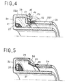
- les figures 4 à 7 sont des vues partielles en demi-coupe axiale de moteurs à plasma selon l'invention montrant différents modes de réalisation de l'ensemble constitué par la chambre tampon, le canal principal, l'anode et le distributeur de gaz ionisable,
- la figure 8 est une vue en perspective d'un exemple de moteur à plasma selon l'invention monté sur la structure d'un satellite, et
- la figure 9 est une vue de détail montrant un exemple de fixation des pièces isolantes définissant le canal principal d'un moteur à plasma selon l'invention.
- On voit sur la figure 1 un exemple de moteur à plasma 20 à dérive fermée d'électrons conforme à l'invention, qui comprend un ensemble de pièces 22 en matériau isolant délimitant un canal annulaire 21 formé en amont d'une première partie constituée par une chambre tampon 23 et en aval d'une deuxième partie constituée par un canal d'accélération 24.
- La chambre annulaire 23 présente de préférence une dimension dans le sens radial qui est de l'ordre du double de la dimension dans le sens radial du canal annulaire d'accélération 24. Dans le sens axial, la chambre tampon 23 peut être un peu plus courte que le canal d'accélération 24 et présente avantageusement une longueur qui est de l'ordre de une fois et demie la dimension d dans le sens radial du canal d'accélération 24.
- Une anode 25, reliée par une ligne électrique 43 à une source de tension continue 44, qui peut être par exemple de l'ordre de 200 à 300 V, est disposée sur les pièces isolantes 22 délimitant le canal annulaire 21, dans une zone située immédiatement en aval de la chambre tampon 23, à l'entrée du canal d'accélération 24. La ligne 43 d'alimentation de l'anode 25 est disposée dans un tube isolant 45 qui traverse le fond du moteur constitué par une plaque 36 formant culasse magnétique et des pièces 223,224 en matériau isolant délimitant la chambre tampon 23.
- Un tube 26 d'alimentation en gaz ionisable tel que du xenon traverse également la culasse 36 et le fond 223 de la chambre tampon 23 pour déboucher dans un distributeur annulaire de gaz 27 placé dans le fond de la chambre tampon 23.
- Le canal 21 délimité par l'ensemble des pièces isolantes 22 est placé dans un circuit magnétique composé essentiellement de trois bobines 31,32,33 et de pièces polaires 34,35.
- Des pièces polaires planes externe 34 et interne 35 sont placées dans le plan de sortie du moteur à l'extérieur du canal d'accélération 24 et déterminent des lignes de champ magnétique qui à la partie ouverte aval du canal d'accélération 24 sont sensiblement parallèles au plan de sortie 59 du moteur 20.
- Le circuit magnétique constitué des pièces polaires 34 et 35 est fermé par un noyau central axial 38 et des barres de liaison 37 disposées à la périphérie du moteur selon une configuration essentiellement cylindrique, le noyau central 38 en matériau ferromagnétique et les barres de liaison 37 en matériau ferromagnétique étant en contact avec la culasse arrière 36. La culasse 36 qui est en matériau ferromagnétique et constitue le fond du moteur peut être protégée par une ou plusieurs couches 30 de matériau super isolant thermiquement qui élimine le flux thermique rayonné vers le satellite.
- Un écran 39 antipollution peut être également disposé entre les pièces isolantes 22 et les barres de liaison 37. Selon une variante de réalisation, les barres de liaison 37 et l'écran 39 sont remplacés par une virole cylindrique ou cylindroconique qui joue à la fois le rôle de fermeture du circuit magnétique et d'écran. Dans tous les cas, l'écran 39 ne doit pas s'opposer au refroidissement du moteur. Il doit donc, soit recevoir un revêtement émissif interne et externe, soit être appliqué de manière à permettre un rayonnement direct vers l'espace.
- Les électrons nécessaires au fonctionnement du moteur sont fournis par une cathode creuse 40 qui peut être de conception classique. La cathode 40, qui est reliée électriquement par une ligne 42 au pôle négatif de la source de tension 44, comporte un circuit 41 d'alimentation en gaz ionisable tel que du xenon, et se trouve placée en aval de la zone de sortie du canal d'accélération 24.
- La cathode creuse 40 fournit un plasma 29 sensiblement au potentiel de référence d'où sont extraits les électrons se dirigeant vers l'anode 25 sous l'effet du champ électrostatique E dû à la différence entre l'anode 25 et la cathode 40.
- Ces électrons ont une trajectoire de dérive en azimuth dans le canal d'accélération 24 sous l'effet du champ électrique E et du champ magnétique B.
- Typiquement, le champ à la sortie du canal 24 est de 150 à 200 Oe.
- Les électrons primaires sont accélérés par le champ électrostatique E, ils heurtent alors la paroi de l'isolateur 22, ce qui fournit des électrons secondaires d'énergie plus faible.
- Les électrons entrent en collision avec les atomes neutres de xenon issus de la chambre tampon 23.
- Les ions xenon ainsi formés sont accélérés par le champ électrostatique E dans le canal d'accélération 24.
- Il n'y a pas de charge d'espace dans le canal d'accélération 24 en raison de la présence des électrons.
- La neutralisation du faisceau d'ions est assurée par une partie des électrons issus de la cathode creuse 40.
- La maîtrise du gradient de champ magnétique radial obtenue grâce à la disposition des bobines 31 à 33 et des pièces polaires 34 et 35 permet de séparer les fonctions d'accélération des ions de la fonction ionisation obtenue dans une zone proche de l'anode 25. Cette zone d'ionisation peut s'étendre partiellement dans la chambre tampon 23.
- Une caractéristique importante de l'invention réside dans l'existence d'une chambre tampon 23 qui permet d'optimiser la zone d'ionisation.
- Dans les moteurs classiques à dérive fermée d'électrons, une partie notable de l'ionisation est localisée dans la partie médiane. Une partie des ions percute les parois, ce qui est une cause d'usure rapide des parois et diminue ainsi la durée de vie du propulseur. La chambre tampon 23 favorise la réduction du gradient de concentration du plasma selon le rayon ainsi que le refroidissement des électrons à l'entrée du canal d'accélération 24, ce qui réduit la divergence du faisceau ionique sur les parois et ainsi évite des pertes d'ions par collision avec ces dernières, ce qui a pour effet d'augmenter le rendement et de réduire la divergence du faisceau à la sortie du moteur.
- Une autre caractéristique importante de l'invention réside dans la présence de trois bobines 31 à 33 qui peuvent présenter des dimensions différentes et permettent d'optimiser le champ magnétique grâce à leur localisation spécifique.
- Ainsi, une première bobine 31 est disposée autour et à l'extérieur du canal principal 24 au voisinage de l'extrémité aval 225 de celui-ci. Une deuxième bobine 32 est disposée autour de l'âme centrale 38 dans une zone faisant face à l'anode 25 et s'étendant partiellement en face de la chambre tampon 23. Une troisième bobine 33 est disposée autour de l'âme centrale 38 entre la deuxième bobine 32 et l'extrémité aval 225 du canal principal d'accélération 24. Les bobines 31,32,33 peuvent présenter des tailles différentes comme représenté sur la figure 1. La présence de trois bobines 31,32,33 bien différenciées a pour conséquence la création de lignes de champ mieux dirigées qui permettent d'obtenir un jet mieux canalisé et plus parallèle que sur les moteurs classiques.
- Selon une variante de réalisation, les bobines 31 à 33 de création d'un champ magnétique peuvent être remplacées au moins partiellement par des aimants permanents dont le point de Curie est supérieur à la température de fonctionnement du moteur.
- La bobine annulaire 31 pourrait également être remplacée par un ensemble de bobines individuelles et disposées autour des différentes barres de liaison 37 constituant le circuit magnétique périphérique.
- L'ensemble des bobines d'induction 31,32 et 33 peuvent également être montées en série avec la source d'alimentation électrique 44 et la cathode 40 de manière à réaliser une autorégulation du courant de décharge.
- Les bobines 31,32,33 peuvent être constituées de fil de cuivre revêtu d'un isolant minéral haute température. Les bobines 31 à 33 peuvent encore être constituées de fil du type coaxial à isolant minéral.
- Le matériau magnétique du circuit constitué des pièces polaires 34,35, de l'âme centrale 38, des barres 37 et de la culasse 36 peut être du fer doux, du fer ultra-pur, ou encore un alliage fer-chrome à haute perméabilité magnétique.
- Le refroidissement des bobines 32 et 33 peut être amélioré par un caloduc placé dans l'axe du noyau magnétique 38 et rejetant la chaleur vers la culasse 36 et la pièce polaire radiale interne 35 rayonnant vers l'espace.
- A titre d'exemple, les pièces polaires 34 et 35 peuvent présenter une dimension de l'ordre d'une vingtaine de millimètres dans le sens axial.
- Le nombre d'ampères-tours de chaque bobine 31,32,33 et le rapport entre la longueur et le diamètre de chacune de ces bobines sont déterminés de manière à produire dans le canal d'accélération un champ magnétique essentiellement radial dont le maximum est situé dans le plan de sortie 59 du moteur, dont les lignes de champ près de la sortie 225 sont essentiellement parallèles à la face de sortie 59 et dont les lignes de champ au voisinage de l'anode 25 sont essentiellement disposées de manière à favoriser l'ionisation du gaz propulsif dans cette région.
- Des exemples de propulseur ionique selon l'invention combinant la présence d'une chambre tampon 23 et d'un ensemble de bobines 31,32,33 différenciées ont permis d'obtenir un rendement électrique de l'ordre de 50 à 70% soit une amélioration en moyenne de l'ordre de 10 à 25% par rapport aux Systèmes antérieurement connus.
- Par ailleurs, dans les réalisations conformes à l'invention, on a obtenu en sortie du moteur un jet quasi-cylindrique avec une très faible divergence du faisceau d'ions de l'ordre de ± 9°. Ainsi, avec un canal d'accélération du diamètre extérieur 80mm, on a à une distance de 80mm à l'extérieur du moteur par rapport au plan de sortie 59, 90% de l'énergie qui reste concentrée dans le diamètre du canal d'accélération.
- D'une manière générale, le moteur selon l'invention permet une plus forte densité de poussée (par exemple de l'ordre de 1 à 2mN/cm2 de densité de poussée aréolaire), donc un moteur plus petit et plus léger à isopoussée, avec un excellent rendement.
- En ce qui concerne la durée de vie, les moteurs connus montrent une durée de vie de l'ordre de 3000h.
- Au contraire, un moteur à plasma conforme à la présente invention permet d'obtenir une durée de vie d'au moins 5000 à 6000 heures en raison de la plus faible érosion du canal 24 liée à la meilleure cylindricité du jet ionisé.
- Le moteur à plasma selon l'invention peut faire l'objet de nombreuses variantes de réalisation.
- Ainsi, le matériau isolant constituant les pièces 22 délimitant la chambre tampon 23 et la canal d'accélération 24 peut être constitué notamment par l'une des combinaisons suivantes :
- céramique BN + B4C + Al2O3
- alumine ultra pure
- composite Al2O3 - Al2O3
- vitrocéramique à base de silice pure ou déposée, par exemple avec un oxyde de terre rare.
- L'isolateur 22 peut être fixé vis-à-vis de l'une des pièces polaires par exemple 34, à l'aide d'une pièce intermédiaire élastique 62 en métal dont le coefficient de dilatation est proche de celui de la céramique (figure 9).
- Ceci permet d'éliminer les contraintes thermiques dues aux différences de coefficient de dilation de la céramique ou similaire et du circuit magnétique. Dans ce cas, les pièces 22 délimitant le canal 24 peuvent présenter un talon 61 de retenue de la pièce intermédiaire élastique 62 et la fixation de celle-ci sur la pièce polaire 34 peut se faire par une vis de liaison 63.
- La liaison entre une matière céramique constituant les pièces isolantes 22 et le métal des pièces polaires 34,35 peut encore être obtenue par exemple par brasure, par soudage par diffusion, par frittage d'une composition cérami-métallique ou par pressage isostatique à chaud.
- La puissance dissipée sous forme des pertes thermiques dans l'anode 25 et le canal 24 peut être évacuée par rayonnement du canal 24 vers l'espace en aval ainsi que par le rayonnement du circuit magnétique. Afin d'éviter des interactions entre le plasma 29 de la cathode 40 et les pièces 22 de l'isolateur, celui-ci peut être entouré par un écran 39 situé entre la pièce polaire 34 et la culasse 36, comme indiqué plus haut. Pour permettre son refroidissement par rayonnement, cet écran 39 est recouvert d'un revêtement à haute émissivité, ou perforé. Dans ce dernier cas, la dimension des trous doit être suffisamment petite pour empêcher la pénétration du plasma.
- Le distributeur 27 de xenon peut être réalisé en acier inoxydable ou en niobium ou encore dans la même céramique que les pièces isolantes 22.
- L'anode 25 peut elle-même être réalisée par exemple en acier inoxydable, en alliage de nickel, en niobium ou en graphite.
- L'alimentation électrique de l'anode 25 est effectuée par un passage céramique/métal hermétique.
- L'alimentation en xenon du distributeur annulaire 27 peut être effectuée par l'intermédiaire d'un tube isolant si le distributeur 27 est lui-même métallique, afin d'éviter que se produise dans la chambre tampon 23 une décharge entre l'anode 25 et le distributeur 27 qui serait à la masse en l'absence de tube isolant.
- On a représenté sur la figure 3 un exemple de tube isolant 300 pour un distributeur 127 métallique qui, selon une variante de réalisation n'est pas disposé dans le fond de la chambre tampon 23, mais dans la partie aval de cette chambre 23 tout en étant séparé du l'anode 25 elle-même placée à l'entrée du canal d'accélération 24. Ce tube isolant peut aussi être disposé radialement à la périphérie de la chambre.
- Sur la figure 3, le tube isolant 300 comprend à titre d'exemple un tube en céramique 301 brasé aux deux extrémités sur des embouts métalliques 302 et rempli interieurement d'un garnissage 303 qui peut être en feutre céramique, en lit de granulés isolants ou encore formé d'un empilement de plaquettes isolantes et de grilles métalliques.
- Dans le cas de la figure 3, le tube isolant 300 est placé le long du canal d'accélération 24 entre la chambre tampon 23 et la bobine 31 de manière à minimiser la longueur totale du moteur.
- Toutefois, le tube isolant 300 pourrait aussi être placé entre la culasse 36 et la chambre tampon 23.
- Les pièces isolantes 22 délimitant la chambre tampon 23 et la canal d'accélération 24 peuvent présenter diverses configurations de même que l'anode 25 qui peut être cylindrique (figures 1,4,7) ou conique (figures 5 et 6).
- Sur la figure 1, une pièce annulaire interne 221 et des pièces complémentaires 222,223,224 rapportées sur la pièce interne 221 délimitent la chambre tampon 23 et le canal annulaire 24 tout en permettant le montage du distributeur 27 et de l'anode 25.
- Dans le cas de la figure 6, les pièces en matériau isolant définissant le canal principal 24 et la chambre tampon 23 comprennent une première pièce 22c formant une paroi externe de la chambre tampon 23 et du canal principal 24 et une deuxième pièce 22d formant une paroi interne de la chambre tampon 23 et du canal principal 24 et le distributeur 27 en gaz ionisable placé dans la chambre tampon 23 constitue lui-même un élément de liaison entre lesdites première et deuxième pièces 22c,22d. L'anode conique 50 peut être montée par l'amont sur une portion de transition conique 56 entre la chambre tampon 23 et le canal d'accélération 24.
- Dans le cas de la figure 4, les pièces en matériau isolant définissant le canal principal 24 et la chambre tampon 23 comprennent une première pièce 22a formant la paroi de la chambre tampon 23 et la paroi interne du canal principal 24 et une deuxième pièce 22b formant la paroi externe du canal principal 24 et l'anode est scellée par des portions 51,52 entre les première et deuxième pièces 22a,22b. La référence 53 désigne un capot optionnel. Le distributeur 27 peut être introduit par l'aval. Le mode de réalisation de la figure 5 est voisin de celui de la figure 4 mais montre une anode 50 conique scellée par des portions 54,55 entre les première et deuxième pièces 22a, 22b.
- Dans le cas des figures 1 et 6, l'anode est rapportée sur une face des pièces 22 en matériau isolant à la jonction entre la chambre tampon 23 et le canal principal 24.
- Dans le cas de la figure 7, l'anode 25 est réalisée en plusieurs tronçons reliés électriquement entre eux (liaison 57). Le distributeur 27 peut être introduit par l'aval. Il existe au niveau de la jonction 58 entre les pièces 22e et 22f en matériau isolant un scellement céramique-céramique permettant de réaliser le canal à partir de deux éléments séparés.
- La figure 8 montre un exemple de mise en oeuvre dans lequel la virole externe 75 en matériau magnétique constitue également une interface de fixation du moteur sur la structure 72 d'un satellite. La référence 71 désigne l'interface mécanique du moteur et la référence 72 le mur du satellite parallèle à l'axe nord-sud du satellite géostationnaire.
- L'angle a représente l'angle d'inclinaison du moteur par rapport à l'axe nord-sud 73 du satellite.
- b qui est ici toujours inférieur à a représente le demi-angle de divergence du faisceau d'ions.
- Des fenêtres 74 de rayonnement sont percées dans la virole 75 et recouvertes d'un écran perforé 76 pouvant être un tamis métallique.
- D'autres exemples de mise en oeuvre du moteur à plasma selon l'invention sont naturellement possibles.
Claims (23)
- Moteur à plasma à dérive fermée d'électrons, comprenant un canal annulaire principal d'ionisation et d'accélération (24) délimité par des pièces (22) en matériau isolant et ouvert à son extrémité aval (225), au moins une cathode creuse (40) disposée à l'extérieur du canal annulaire principal (24) du côté de la partie aval de celui-ci, une anode annulaire (25) concentrique au canal annulaire principal (24) et disposée à distance de l'extrémité aval ouverte (225), des premiers et deuxièmes moyens (41,26) d'alimentation en gaz ionisable associés respectivement à la cathode creuse (40) et à l'anode annulaire (25), un circuit magnétique (31 à 33, 34 à 38) de création d'un champ magnétique dans le canal annulaire principal (24), et une chambre tampon annulaire (23) qui présente dans le sens radial une dimension plus grande que celle du canal annulaire principal (24) et s'étend en amont de celui-ci au-delà de la zone dans laquelle est placée l'anode annulaire (25), les deuxièmes moyens (26) d'alimentation en gaz ionisable débouchant dans la chambre tampon annulaire (23) en amont de l'anode (25) à travers un distributeur annulaire (27) dans une zone distincte de la zone portant l'anode (25), et le circuit magnétique comprenant plusieurs moyens distincts (31 à 33) de création d'un champ magnétique et des pièces polaires radiales planes (34, 35) interne (35) et externe (34) disposées au niveau de la face de sortie de part et d'autre du canal principal (24) et reliées entre elles par une âme centrale (38), une culasse (36) et un circuit magnétique périphérique (37) disposé axialement à l'extérieur du canal principal (24) et de la chambre tampon (23),
caractérisé en ce que les moyens (31 à 33, 34 à 38) de création d'un champ magnétique dans le canal principal (24) sont adaptés pour produire dans ce canal principal (24) un champ magnétique essentiellement radial qui présente un gradient avec une induction maximale à l'extrémité aval (225) du canal (24), les lignes de champ étant essentiellement parallèles à la face de sortie (34,35) perpendiculaire à l'axe du moteur, à l'extrémité aval (225) du canal (24), et une induction minimale dans la zone de transition située au voisinage de l'anode (25) entre la chambre tampon (23) et le canal principal (24) de manière à favoriser l'ionisation du gaz ionisable, et en ce que les moyens distincts; (31 à 33) de création d'un champ magnétique comprennent un premier moyen (31) disposé autour et à l'extérieur du canal principal (24) au voisinage de l'extrémité aval (225) de celui-ci, un deuxième moyen (32) disposé autour de l'âme centrale (38) dans une zone faisant face à l'anode (25) et s'étendant partiellement en face de la chambre tampon (23) et un troisième moyen (33) disposé autour de l'âme centrale (38) entre le deuxième moyen (32) et l'extrémité aval (225) du canal principal (24). - Moteur à plasma selon la revendication 1, caractérisé en ce que la chambre tampon (23) présente dans le sens radial une dimension qui est de l'ordre du double de la dimension radiale du canal principal (24).
- Moteur à plasma selon la revendication 1 ou la revendication 2, caractérisé en ce que la chambre tampon (23) présente dans le sens axial une dimension qui est de l'ordre de 1,5 fois la dimension radiale du canal principal (24).
- Moteur à plasma selon l'une quelconque des revendications 1 à 3, caractérisé en ce que les premier, deuxième et troisième moyens (31,32,33) de création d'un champ magnétique présentent des tailles différentes.
- Moteur à plasma selon l'une quelconque des revendications 1 à 4, caractérisé en ce que les premier, deuxième et troisième moyens (31,32,33) de création d'un champ magnétique sont constitués par des bobines d'induction.
- Moteur à plasma selon l'une quelconque des revendications 1 à 5, caractérisé en ce que les premier, deuxième et troisième moyens (31,32,33) de création d'un champ magnétique sont formés au moins partiellement par des aimants permanents dont le point de Curie est supérieur à la température de fonctionnement du moteur.
- Moteur à plasma selon l'une quelconque des revendications 1 à 6, caractérisé en ce que le circuit magnétique périphérique (37) comprend un ensemble de barreaux de liaison entre la pièce polaire radiale externe (34) et la culasse (36).
- Moteur à plasma selon la revendication 5 et la revendication 7, caractérisé en ce que le premier moyen (31) de création d'un champ magnétique comprend un ensemble de bobines individuelles disposées autour des barreaux (37) constituant le circuit magnétique périphérique.
- Moteur à plasma selon l'une quelconque des revendications 1 à 6, caractérisé en ce que le circuit magnétique périphérique (37) est constitué par une virole.
- Moteur à plasma selon la revendication 5, caractérisé en ce que les bobines d'induction constituant les premier, deuxième et troisième moyens (31,32,33) de création d'un champ magnétique sont montées en série entre une source d'alimentation électrique (44) et la cathode creuse (40).
- Moteur à plasma selon l'une quelconque des revendications 1 à 10, caractérisé en ce que le distributeur annulaire (27) de gaz ionisable disposé dans la chambre tampon (23) est réalisé en un matériau isolant électriquement.
- Moteur à plasma selon l'une quelconque des revendications 1 à 10, caractérisé en ce que le distributeur annulaire (27) de gaz ionisable disposé dans la chambre tampon (23) est métallique et en ce que le tube (26) d'alimentation en gaz ionisable débouchant dans le distributeur annulaire (27) comprend des moyens (300) d'isolation électrique.
- Moteur à plasma selon la revendication 12, caractérisé en ce que les moyens (300) d'isolation électrique du tube (26) d'alimentation en gaz ionisable sont disposés entre la culasse (36) et la chambre tampon (23).
- Moteur à plasma selon la revendication 12, caractérisé en ce que le tube (26) d'alimentation en gaz ionisable et ses moyens (300) d'isolation électrique sont disposés le long du canal principal (24) entre la chambre tampon (23) et le premier moyen (31) de création d'un champ magnétique.
- Moteur à plasma selon la revendication 5, caractérisé en ce qu'il comprend un caloduc placé dans l'axe de l'âme centrale (38) portant les bobines constituant les deuxième et troisième moyens de création d'un champ magnétique (32, 33) et rejetant la chaleur vers la pièce polaire radiale interne (35) et la culasse (36).
- Moteur à plasma selon l'une quelconque des revendications 1 à 15, caractérisé en ce que les pièces (22) en matériau isolant définissant le canal principal (24) et la chambre tampon (23) comprennent une première pièce (22c) formant une paroi externe de la chambre tampon (23) et du canal principal (24) et une deuxième pièce (22d) formant une paroi interne de la chambre tampon (23) et du canal principal (24) et en ce que le distributeur (27) en gaz ionisable placé dans la chambre tampon (23) constitue lui-même un élément de liaison entre lesdites première et deuxième pièces (22c,22d).
- Moteur à plasma selon l'une quelconque des revendications 1 à 15, caractérisé en ce que les pièces (22) en matériau isolant définissant le canal principal (24) et la chambre tampon (23) comprennent une première pièce (22a) formant la paroi de la chambre tampon (23) et la paroi interne du canal principal (24) et une deuxième pièce (22b) formant la paroi externe du canal principal (24) et en ce que l'anode (25) est scellée entre la première et deuxième pièces (22a,22b).
- Moteur à plasma selon l'une quelconque des revendications 1 à 16, caractérisé en ce que l'anode (25) est rapportée sur une face des pièces (22) en matériau isolant à la jonction entre la chambre tampon (23) et le canal principal (24).
- Moteur à plasma selon l'une quelconque des revendications 1 à 18, caractérisé en ce que l'anode (25) présente une forme cylindrique.
- Moteur à plasma selon l'une quelconque des revendications 1 à 18, caractérisé en ce que l'anode (50) présente une forme tronconique.
- Moteur à plasma selon l'une quelconque des revendications 1 à 20, caractérisé en ce que l'anode (25) est constituée en plusieurs tronçons disposés dans la chambre tampon (23) ou à l'entrée du canal principal (24) et reliés électriquement entre eux.
- Moteur à plasma selon l'une quelconque des revendications 1 à 21, caractérisé en ce que les pièces isolantes (22) définissant le canal principal (24) sont fixées sur la pièce polaire radiale externe (34) à l'aide d'un assemblage à talon (61) et rondelle élastique (62).
- Moteur à plasma selon la revendication 10, caractérisé en ce que la virole externe (75) en matériau magnétique constitue également une interface de fixation du moteur sur la structure (72) d'un satellite.
Applications Claiming Priority (4)
| Application Number | Priority Date | Filing Date | Title |
|---|---|---|---|
| FR9208744A FR2693770B1 (fr) | 1992-07-15 | 1992-07-15 | Moteur à plasma à dérive fermée d'électrons. |
| FR9208744 | 1992-07-15 | ||
| PCT/FR1992/000836 WO1994002738A1 (fr) | 1992-07-15 | 1992-09-01 | Moteur a plasma a derive fermee d'electrons |
| CA002142607A CA2142607A1 (fr) | 1992-07-15 | 1993-06-21 | Accelerateur de plasma court a derive electronique confinee |
Publications (2)
| Publication Number | Publication Date |
|---|---|
| EP0650557A1 EP0650557A1 (fr) | 1995-05-03 |
| EP0650557B1 true EP0650557B1 (fr) | 1997-05-07 |
Family
ID=25677792
Family Applications (1)
| Application Number | Title | Priority Date | Filing Date |
|---|---|---|---|
| EP92919481A Expired - Lifetime EP0650557B1 (fr) | 1992-07-15 | 1992-09-01 | Moteur a plasma a derive fermee d'electrons |
Country Status (9)
| Country | Link |
|---|---|
| US (1) | US5581155A (fr) |
| EP (1) | EP0650557B1 (fr) |
| JP (1) | JP3083561B2 (fr) |
| CA (1) | CA2142607A1 (fr) |
| DE (1) | DE69219625T2 (fr) |
| ES (1) | ES2101870T3 (fr) |
| FR (1) | FR2693770B1 (fr) |
| RU (1) | RU2121075C1 (fr) |
| WO (2) | WO1994002738A1 (fr) |
Families Citing this family (88)
| Publication number | Priority date | Publication date | Assignee | Title |
|---|---|---|---|---|
| WO1996006518A1 (fr) * | 1994-08-25 | 1996-02-29 | Aeorospatiale Societe Nationale Industrielle | Accelerateur plasmatique a flux electronique ferme |
| RU2088802C1 (ru) * | 1995-12-09 | 1997-08-27 | Исследовательский центр им.М.В.Келдыша | Холловский двигатель |
| ES2296295T3 (es) * | 1995-12-09 | 2008-04-16 | Astrium Sas | Propulsor de efecto hall que puede guiarse. |
| RU2092983C1 (ru) * | 1996-04-01 | 1997-10-10 | Исследовательский центр им.М.В.Келдыша | Плазменный ускоритель |
| FR2743191B1 (fr) * | 1995-12-29 | 1998-03-27 | Europ Propulsion | Source d'ions a derive fermee d'electrons |
| US5892329A (en) * | 1997-05-23 | 1999-04-06 | International Space Technology, Inc. | Plasma accelerator with closed electron drift and conductive inserts |
| RU2139646C1 (ru) * | 1998-04-07 | 1999-10-10 | Федеральное государственное унитарное предприятие "Исследовательский центр им.М.В.Келдыша" | Плазменный ускоритель с замкнутым дрейфом электронов |
| WO1999063222A1 (fr) * | 1998-06-05 | 1999-12-09 | Primex Aerospace Company | Distribution uniforme de gaz dans des accelerateurs d'ions a courant d'electrons ferme |
| US6612105B1 (en) | 1998-06-05 | 2003-09-02 | Aerojet-General Corporation | Uniform gas distribution in ion accelerators with closed electron drift |
| US6215124B1 (en) | 1998-06-05 | 2001-04-10 | Primex Aerospace Company | Multistage ion accelerators with closed electron drift |
| US6208080B1 (en) | 1998-06-05 | 2001-03-27 | Primex Aerospace Company | Magnetic flux shaping in ion accelerators with closed electron drift |
| US6031334A (en) * | 1998-06-17 | 2000-02-29 | Primex Technologies, Inc. | Method and apparatus for selectively distributing power in a thruster system |
| RU2139647C1 (ru) * | 1998-06-18 | 1999-10-10 | Бугрова Антонина Ивановна | Плазменный ускоритель с замкнутым дрейфом электронов |
| US6075321A (en) * | 1998-06-30 | 2000-06-13 | Busek, Co., Inc. | Hall field plasma accelerator with an inner and outer anode |
| FR2782884B1 (fr) * | 1998-08-25 | 2000-11-24 | Snecma | Propulseur a plasma a derive fermee d'electrons adapte a de fortes charges thermiques |
| US6064156A (en) * | 1998-09-14 | 2000-05-16 | The United States Of America As Represented By The Administrator Of Nasa | Process for ignition of gaseous electrical discharge between electrodes of a hollow cathode assembly |
| US6150764A (en) * | 1998-12-17 | 2000-11-21 | Busek Co., Inc. | Tandem hall field plasma accelerator |
| FR2788084B1 (fr) * | 1998-12-30 | 2001-04-06 | Snecma | Propulseur a plasma a derive fermee d'electrons a vecteur poussee orientable |
| RU2156555C1 (ru) * | 1999-05-18 | 2000-09-20 | Государственное унитарное предприятие "Всероссийский электротехнический институт им. В.И. Ленина" | Способ получения и ускорения плазмы и ускоритель плазмы с замкнутым дрейфом электронов для его осуществления |
| RU2162624C1 (ru) * | 1999-05-26 | 2001-01-27 | Байдаков Сергей Георгиевич | Способ ускорения ионов и устройство для его реализации |
| US6334302B1 (en) | 1999-06-28 | 2002-01-01 | The United States Of America As Represented By The Administrator Of The National Aeronautics And Space Administration | Variable specific impulse magnetoplasma rocket engine |
| DE10014033C2 (de) * | 2000-03-22 | 2002-01-24 | Thomson Tubes Electroniques Gm | Plasma-Beschleuniger-Anordnung |
| DE10014034C2 (de) * | 2000-03-22 | 2002-01-24 | Thomson Tubes Electroniques Gm | Plasma-Beschleuniger-Anordnung |
| RU2183764C2 (ru) * | 2000-06-06 | 2002-06-20 | Кириллов Леонид Иванович | Космический двигатель |
| RU2188337C2 (ru) * | 2000-07-12 | 2002-08-27 | Федеральное государственное унитарное предприятие Российского авиационно-космического агентства "Опытное конструкторское бюро "Факел" | Плазменный двигатель с замкнутым дрейфом электронов |
| RU2188521C2 (ru) * | 2000-07-12 | 2002-08-27 | Федеральное государственное унитарное предприятие Российского авиационно-космического агентства "Опытное конструкторское бюро "Факел" | Плазменный двигатель с замкнутым дрейфом электронов |
| RU2191290C2 (ru) * | 2000-08-17 | 2002-10-20 | Федеральное государственное унитарное предприятие Российского авиационно-космического агентства "Опытное конструкторское бюро "Факел" | Плазменный двигатель с замкнутым дрейфом электронов |
| RU2196922C2 (ru) * | 2000-08-17 | 2003-01-20 | Федеральное государственное унитарное предприятие Российского авиационно-космического агентства "Опытное конструкторское бюро "Факел" | Плазменный двигатель с замкнутым дрейфом электронов |
| RU2191289C2 (ru) * | 2000-08-17 | 2002-10-20 | Федеральное государственное унитарное предприятие Российского авиационно-космического агентства "Опытное конструкторское бюро "Факел" | Плазменный двигатель с замкнутым дрейфом электронов |
| RU2204053C2 (ru) * | 2000-09-29 | 2003-05-10 | Федеральное государственное унитарное предприятие Российского авиационно-космического агентства "Опытное конструкторское бюро "Факел" | Плазменный двигатель с замкнутым дрейфом электронов |
| US6486593B1 (en) | 2000-09-29 | 2002-11-26 | The United States Of America As Represented By The United States Department Of Energy | Plasma accelerator |
| RU2191291C2 (ru) * | 2000-10-04 | 2002-10-20 | Федеральное государственное унитарное предприятие Российского авиационно-космического агентства "Опытное конструкторское бюро "Факел" | Плазменный двигатель с замкнутым дрейфом электронов |
| RU2196397C2 (ru) * | 2000-12-28 | 2003-01-10 | Петросов Валерий Александрович | Способ и устройство для ускорения ионов в плазменных ускорителях холловского типа |
| RU2200874C2 (ru) * | 2001-02-28 | 2003-03-20 | Федеральное государственное унитарное предприятие Российского авиационно-космического агентства "Опытное конструкторское бюро "Факел" | Электроракетная двигательная установка |
| AU2002257299A1 (en) * | 2001-06-19 | 2003-01-02 | Toky0 Electron Limited | A closed-drift hall effect plasma vacuum pump for process reactors |
| DE10147998A1 (de) * | 2001-09-28 | 2003-04-10 | Unaxis Balzers Ag | Verfahren und Vorrichtung zur Erzeugung eines Plasmas |
| RU2209532C2 (ru) * | 2001-10-10 | 2003-07-27 | Сорокин Игорь Борисович | Плазменный ускоритель с замкнутым дрейфом электронов |
| DE10153723A1 (de) * | 2001-10-31 | 2003-05-15 | Thales Electron Devices Gmbh | Plasmabeschleuniger-Anordnung |
| RU2225533C2 (ru) * | 2002-04-08 | 2004-03-10 | Красноярский государственный технический университет | Электрический ракетный двигатель |
| RU2230221C2 (ru) * | 2002-04-12 | 2004-06-10 | Федеральное государственное унитарное предприятие Российского космического агентства "Опытное конструкторское бюро "Факел" | Электрореактивная двигательная установка |
| US6696792B1 (en) | 2002-08-08 | 2004-02-24 | The United States Of America As Represented By The United States National Aeronautics And Space Administration | Compact plasma accelerator |
| US7461502B2 (en) | 2003-03-20 | 2008-12-09 | Elwing Llc | Spacecraft thruster |
| RU2244159C2 (ru) * | 2003-06-05 | 2005-01-10 | Кочетков Борис Федорович | Ракетный двигатель для космических аппаратов |
| FR2857555B1 (fr) * | 2003-07-09 | 2005-10-14 | Snecma Moteurs | Accelerateur a plasma a derive fermee d'electrons |
| ATE454553T1 (de) * | 2004-09-22 | 2010-01-15 | Elwing Llc | Antriebssystem für raumfahrzeuge |
| JP2006147449A (ja) * | 2004-11-24 | 2006-06-08 | Japan Aerospace Exploration Agency | 高周波放電プラズマ生成型二段式ホール効果プラズマ加速器 |
| US7617092B2 (en) * | 2004-12-01 | 2009-11-10 | Microsoft Corporation | Safe, secure resource editing for application localization |
| US7624566B1 (en) | 2005-01-18 | 2009-12-01 | The United States Of America As Represented By The Administrator Of National Aeronautics And Space Administration | Magnetic circuit for hall effect plasma accelerator |
| US7500350B1 (en) | 2005-01-28 | 2009-03-10 | The United States Of America As Represented By The Administrator Of The National Aeronautics And Space Administration | Elimination of lifetime limiting mechanism of hall thrusters |
| US7420182B2 (en) * | 2005-04-27 | 2008-09-02 | Busek Company | Combined radio frequency and hall effect ion source and plasma accelerator system |
| JP4816004B2 (ja) * | 2005-10-28 | 2011-11-16 | 三菱電機株式会社 | ホールスラスタ及び宇宙航行体 |
| JP4816179B2 (ja) * | 2006-03-20 | 2011-11-16 | 三菱電機株式会社 | ホールスラスタ |
| US9447779B2 (en) | 2006-11-09 | 2016-09-20 | Alexander Kapulkin | Low-power hall thruster |
| JP2008223655A (ja) * | 2007-03-14 | 2008-09-25 | Japan Aerospace Exploration Agency | ホール型電気推進機 |
| DE102007044074B4 (de) * | 2007-09-14 | 2011-05-26 | Thales Electron Devices Gmbh | Elektrostatische Ionenbeschleunigeranordnung |
| US8407979B1 (en) | 2007-10-29 | 2013-04-02 | The United States Of America As Represented By The Administrator Of The National Aeronautics And Space Administration | Magnetically-conformed, variable area discharge chamber for hall thruster, and method |
| CN105154856B (zh) | 2008-08-04 | 2018-08-10 | 北美Agc平板玻璃公司 | 等离子体源和用等离子体增强的化学气相沉积来沉积薄膜涂层的方法 |
| RU2411393C2 (ru) * | 2008-10-17 | 2011-02-10 | Георгий Александрович Ковальский | Высоковольтный ионный двигатель для космических аппаратов |
| FR2941503B1 (fr) * | 2009-01-27 | 2011-03-04 | Snecma | Propulseur a derive fermee d'electrons |
| FR2950114B1 (fr) * | 2009-09-17 | 2012-07-06 | Snecma | Moteur a effet hall avec refroidissement de la ceramique interne |
| FR2950115B1 (fr) * | 2009-09-17 | 2012-11-16 | Snecma | Propulseur plasmique a effet hall |
| US8468794B1 (en) | 2010-01-15 | 2013-06-25 | The United States Of America As Represented By The Administrator Of National Aeronautics And Space Administration | Electric propulsion apparatus |
| FR2959534B1 (fr) * | 2010-04-29 | 2012-07-13 | Snecma | Moteur a effet hall avec regulation de la temperature du dispositif de chauffage de la cathode |
| EP2431995A1 (fr) * | 2010-09-17 | 2012-03-21 | Asociacion de la Industria Navarra (AIN) | Dispositif d'ionisation |
| FR2976029B1 (fr) | 2011-05-30 | 2016-03-11 | Snecma | Propulseur a effet hall |
| US9679869B2 (en) | 2011-09-02 | 2017-06-13 | Skyworks Solutions, Inc. | Transmission line for high performance radio frequency applications |
| FR2979956B1 (fr) | 2011-09-09 | 2013-09-27 | Snecma | Systeme de propulsion electrique a propulseurs a plasma stationnaire |
| FR2986577B1 (fr) * | 2012-02-06 | 2016-05-20 | Snecma | Propulseur a effet hall |
| US9054065B2 (en) * | 2012-04-30 | 2015-06-09 | Skyworks Solutions, Inc. | Bipolar transistor having collector with grading |
| KR101584042B1 (ko) | 2012-06-14 | 2016-01-08 | 스카이워크스 솔루션즈, 인코포레이티드 | 관련된 시스템, 장치, 및 방법을 포함하는 전력 증폭기 모듈 |
| RU2543103C2 (ru) * | 2013-06-24 | 2015-02-27 | Открытое акционерное общество "Ракетно-космическая корпорация "Энергия" имени С.П. Королева" | Ионный двигатель |
| US10273944B1 (en) * | 2013-11-08 | 2019-04-30 | The United States Of America As Represented By The Administrator Of National Aeronautics And Space Administration | Propellant distributor for a thruster |
| CN103953517B (zh) * | 2014-05-13 | 2016-08-31 | 哈尔滨工业大学 | 霍尔推进器改进装置 |
| MX2017007356A (es) | 2014-12-05 | 2018-04-11 | Agc Flat Glass Europe S A | Fuente de plasma del catodo hueco. |
| CN107615888B (zh) | 2014-12-05 | 2022-01-04 | 北美Agc平板玻璃公司 | 利用宏粒子减少涂层的等离子体源和将等离子体源用于沉积薄膜涂层和表面改性的方法 |
| US9721764B2 (en) | 2015-11-16 | 2017-08-01 | Agc Flat Glass North America, Inc. | Method of producing plasma by multiple-phase alternating or pulsed electrical current |
| US9721765B2 (en) | 2015-11-16 | 2017-08-01 | Agc Flat Glass North America, Inc. | Plasma device driven by multiple-phase alternating or pulsed electrical current |
| US10573499B2 (en) | 2015-12-18 | 2020-02-25 | Agc Flat Glass North America, Inc. | Method of extracting and accelerating ions |
| US10242846B2 (en) | 2015-12-18 | 2019-03-26 | Agc Flat Glass North America, Inc. | Hollow cathode ion source |
| SG11201805171YA (en) * | 2015-12-18 | 2018-07-30 | Agc Flat Glass Na Inc | Hollow cathode ion source and method of extracting and accelerating ions |
| RU2691702C2 (ru) * | 2017-08-15 | 2019-06-17 | Федеральное государственное бюджетное образовательное учреждение высшего образования Балтийский государственный технический университет "ВОЕНМЕХ" им. Д.Ф. Устинова (БГТУ "ВОЕНМЕХ") | Гиперзвуковой прямоточный воздушно-реактивный двигатель |
| FR3094557B1 (fr) * | 2019-03-26 | 2024-03-01 | 2 Univ De Versailles Saint Quentin En Yvelines | Dispositif d’éjection d’ions à effet Hall |
| RU2726152C1 (ru) * | 2019-12-09 | 2020-07-09 | Федеральное государственное бюджетное военное образовательное учреждение высшего образования "Военно-космическая академия имени А.Ф. Можайского" Министерства обороны Российской Федерации | Электрический ракетный двигатель (варианты) |
| US12078153B2 (en) * | 2021-04-15 | 2024-09-03 | California Institute Of Technology | Thermally managed electric propulsion systems |
| RU2764496C1 (ru) * | 2021-04-20 | 2022-01-17 | Публичное акционерное общество "Ракетно-космическая корпорация "Энергия" имени С.П. Королева" | Магнитоплазменный электрореактивный двигатель |
| US12424896B2 (en) | 2022-03-25 | 2025-09-23 | California Institute Of Technology | Electric motor with integrated heat exchanger |
| CN115681057B (zh) * | 2023-01-03 | 2023-06-02 | 国科大杭州高等研究院 | 一种霍尔推进系统及其运行方法 |
| US12504006B2 (en) * | 2024-05-17 | 2025-12-23 | California Institute Of Technology | Gas distributor for electric propulsion systems |
Family Cites Families (5)
| Publication number | Priority date | Publication date | Assignee | Title |
|---|---|---|---|---|
| US4841197A (en) * | 1986-05-28 | 1989-06-20 | Nihon Shinku Gijutsu Kabushiki Kaisha | Double-chamber ion source |
| US4862032A (en) * | 1986-10-20 | 1989-08-29 | Kaufman Harold R | End-Hall ion source |
| JPS6477764A (en) * | 1987-09-18 | 1989-03-23 | Toshiba Corp | Hall type ion thruster |
| EP0463408A3 (en) * | 1990-06-22 | 1992-07-08 | Hauzer Techno Coating Europe Bv | Plasma accelerator with closed electron drift |
| DE69304336T2 (de) * | 1993-06-21 | 1997-01-23 | Europ De Propulsion S E P Soc | Plasmamotor geringer länge mit geschlossenem elektronendrift |
-
1992
- 1992-07-15 FR FR9208744A patent/FR2693770B1/fr not_active Expired - Lifetime
- 1992-09-01 EP EP92919481A patent/EP0650557B1/fr not_active Expired - Lifetime
- 1992-09-01 US US08/367,279 patent/US5581155A/en not_active Expired - Lifetime
- 1992-09-01 WO PCT/FR1992/000836 patent/WO1994002738A1/fr not_active Ceased
- 1992-09-01 ES ES92919481T patent/ES2101870T3/es not_active Expired - Lifetime
- 1992-09-01 DE DE69219625T patent/DE69219625T2/de not_active Expired - Lifetime
- 1992-09-01 JP JP06504187A patent/JP3083561B2/ja not_active Expired - Fee Related
- 1992-09-01 RU RU95105253A patent/RU2121075C1/ru active
-
1993
- 1993-06-21 WO PCT/FR1993/000610 patent/WO1994002739A1/fr not_active Ceased
- 1993-06-21 CA CA002142607A patent/CA2142607A1/fr not_active Abandoned
Also Published As
| Publication number | Publication date |
|---|---|
| WO1994002738A1 (fr) | 1994-02-03 |
| DE69219625D1 (de) | 1997-06-12 |
| US5581155A (en) | 1996-12-03 |
| RU2121075C1 (ru) | 1998-10-27 |
| JP3083561B2 (ja) | 2000-09-04 |
| RU95105253A (ru) | 1996-10-27 |
| FR2693770B1 (fr) | 1994-10-14 |
| JPH08500930A (ja) | 1996-01-30 |
| WO1994002739A1 (fr) | 1994-02-03 |
| FR2693770A1 (fr) | 1994-01-21 |
| EP0650557A1 (fr) | 1995-05-03 |
| DE69219625T2 (de) | 1997-11-13 |
| CA2142607A1 (fr) | 1995-01-05 |
| ES2101870T3 (es) | 1997-07-16 |
Similar Documents
| Publication | Publication Date | Title |
|---|---|---|
| EP0662195B1 (fr) | Moteur a plasma de longueur reduite a derive fermee d'electrons | |
| FR2693770A1 (fr) | Moteur à plasma à dérive fermée d'électrons. | |
| EP0781921B1 (fr) | Source d'ions à dérive fermée d'électrons | |
| EP0982976B1 (fr) | Propulseur à plasma à dérive fermée d'électrons adapté à de fortes charges thermiques | |
| EP2433002B1 (fr) | Propulseur a plasma a effet hall | |
| EP2798209B1 (fr) | Propulseur plasmique et procede de generation d'une poussee propulsive plasmique | |
| EP1496727B1 (fr) | Accélérateur à plasma à dérive fermée d'électrons | |
| EP0914560B1 (fr) | PROPULSEUR A PLASMA avec DISPOSITIF DE CONCENTRATION DE FAISCEAU D'IONS | |
| FR2799576A1 (fr) | Source d'ions a haute frequence notamment moteur pour engin spatial | |
| FR2842261A1 (fr) | Propulseur plasmique a effet hall | |
| EP3250822B1 (fr) | Propulseur à effet hall et engin spatial comprenant un tel propulseur | |
| EP2652766B1 (fr) | Dispositif generateur d'ions a resonance cyclotronique electronique | |
| EP3574719B1 (fr) | Systeme de generation d'un jet plasma d'ions metalliques | |
| EP3526472A1 (fr) | Propulseur ionique à décharge plasma externe | |
| CA2139581A1 (fr) | Moteur a plasma a derive fermee d'electrons | |
| FR3094557A1 (fr) | Dispositif d’éjection d’ions à effet Hall | |
| EP0813223B1 (fr) | Dispositif pour engendrer un champ magnétique et source ecr comportant ce dispositif | |
| WO2025133525A1 (fr) | Cathode pour un propulseur ionique a effet hall |
Legal Events
| Date | Code | Title | Description |
|---|---|---|---|
| PUAI | Public reference made under article 153(3) epc to a published international application that has entered the european phase |
Free format text: ORIGINAL CODE: 0009012 |
|
| 17P | Request for examination filed |
Effective date: 19950111 |
|
| AK | Designated contracting states |
Kind code of ref document: A1 Designated state(s): CH DE ES GB IT LI NL SE |
|
| 17Q | First examination report despatched |
Effective date: 19951024 |
|
| GRAG | Despatch of communication of intention to grant |
Free format text: ORIGINAL CODE: EPIDOS AGRA |
|
| GRAH | Despatch of communication of intention to grant a patent |
Free format text: ORIGINAL CODE: EPIDOS IGRA |
|
| GRAH | Despatch of communication of intention to grant a patent |
Free format text: ORIGINAL CODE: EPIDOS IGRA |
|
| GRAA | (expected) grant |
Free format text: ORIGINAL CODE: 0009210 |
|
| AK | Designated contracting states |
Kind code of ref document: B1 Designated state(s): CH DE ES GB IT LI NL SE |
|
| REG | Reference to a national code |
Ref country code: CH Ref legal event code: EP |
|
| REF | Corresponds to: |
Ref document number: 69219625 Country of ref document: DE Date of ref document: 19970612 |
|
| REG | Reference to a national code |
Ref country code: CH Ref legal event code: NV Representative=s name: BOVARD AG PATENTANWAELTE |
|
| REG | Reference to a national code |
Ref country code: ES Ref legal event code: FG2A Ref document number: 2101870 Country of ref document: ES Kind code of ref document: T3 |
|
| PGFP | Annual fee paid to national office [announced via postgrant information from national office to epo] |
Ref country code: NL Payment date: 19970821 Year of fee payment: 6 |
|
| GBT | Gb: translation of ep patent filed (gb section 77(6)(a)/1977) |
Effective date: 19970801 |
|
| PGFP | Annual fee paid to national office [announced via postgrant information from national office to epo] |
Ref country code: ES Payment date: 19970919 Year of fee payment: 6 |
|
| PGFP | Annual fee paid to national office [announced via postgrant information from national office to epo] |
Ref country code: CH Payment date: 19970924 Year of fee payment: 6 |
|
| PGFP | Annual fee paid to national office [announced via postgrant information from national office to epo] |
Ref country code: SE Payment date: 19970926 Year of fee payment: 6 |
|
| PLBE | No opposition filed within time limit |
Free format text: ORIGINAL CODE: 0009261 |
|
| STAA | Information on the status of an ep patent application or granted ep patent |
Free format text: STATUS: NO OPPOSITION FILED WITHIN TIME LIMIT |
|
| 26N | No opposition filed | ||
| PG25 | Lapsed in a contracting state [announced via postgrant information from national office to epo] |
Ref country code: SE Free format text: LAPSE BECAUSE OF NON-PAYMENT OF DUE FEES Effective date: 19980902 Ref country code: ES Free format text: LAPSE BECAUSE OF THE APPLICANT RENOUNCES Effective date: 19980902 |
|
| PG25 | Lapsed in a contracting state [announced via postgrant information from national office to epo] |
Ref country code: LI Free format text: LAPSE BECAUSE OF NON-PAYMENT OF DUE FEES Effective date: 19980930 Ref country code: CH Free format text: LAPSE BECAUSE OF NON-PAYMENT OF DUE FEES Effective date: 19980930 |
|
| PG25 | Lapsed in a contracting state [announced via postgrant information from national office to epo] |
Ref country code: NL Free format text: LAPSE BECAUSE OF NON-PAYMENT OF DUE FEES Effective date: 19990401 |
|
| REG | Reference to a national code |
Ref country code: CH Ref legal event code: PL |
|
| EUG | Se: european patent has lapsed |
Ref document number: 92919481.9 |
|
| NLV4 | Nl: lapsed or anulled due to non-payment of the annual fee |
Effective date: 19990401 |
|
| REG | Reference to a national code |
Ref country code: GB Ref legal event code: 732E |
|
| REG | Reference to a national code |
Ref country code: ES Ref legal event code: FD2A Effective date: 20001009 |
|
| REG | Reference to a national code |
Ref country code: GB Ref legal event code: IF02 |
|
| PGFP | Annual fee paid to national office [announced via postgrant information from national office to epo] |
Ref country code: GB Payment date: 20100826 Year of fee payment: 19 |
|
| PGFP | Annual fee paid to national office [announced via postgrant information from national office to epo] |
Ref country code: DE Payment date: 20100909 Year of fee payment: 19 |
|
| PGFP | Annual fee paid to national office [announced via postgrant information from national office to epo] |
Ref country code: IT Payment date: 20110826 Year of fee payment: 20 |
|
| GBPC | Gb: european patent ceased through non-payment of renewal fee |
Effective date: 20110901 |
|
| REG | Reference to a national code |
Ref country code: GB Ref legal event code: 732E Free format text: REGISTERED BETWEEN 20120517 AND 20120523 |
|
| REG | Reference to a national code |
Ref country code: DE Ref legal event code: R119 Ref document number: 69219625 Country of ref document: DE Effective date: 20120403 |
|
| PG25 | Lapsed in a contracting state [announced via postgrant information from national office to epo] |
Ref country code: DE Free format text: LAPSE BECAUSE OF NON-PAYMENT OF DUE FEES Effective date: 20120403 |
|
| PG25 | Lapsed in a contracting state [announced via postgrant information from national office to epo] |
Ref country code: GB Free format text: LAPSE BECAUSE OF NON-PAYMENT OF DUE FEES Effective date: 20110901 |
|
| REG | Reference to a national code |
Ref country code: DE Ref legal event code: R082 Ref document number: 69219625 Country of ref document: DE Representative=s name: BEETZ & PARTNER PATENT- UND RECHTSANWAELTE, DE |
|
| REG | Reference to a national code |
Ref country code: DE Ref legal event code: R082 Ref document number: 69219625 Country of ref document: DE Representative=s name: BEETZ & PARTNER MBB PATENT- UND RECHTSANWAELTE, DE Effective date: 20130320 Ref country code: DE Ref legal event code: R082 Ref document number: 69219625 Country of ref document: DE Representative=s name: BEETZ & PARTNER PATENT- UND RECHTSANWAELTE, DE Effective date: 20130320 Ref country code: DE Ref legal event code: R081 Ref document number: 69219625 Country of ref document: DE Owner name: SNECMA, FR Free format text: FORMER OWNER: SOCIETE NATIONALE D'ETUDE ET DE CONSTRUCTION DE MOTEURS D'AVIATION, PARIS, FR Effective date: 20130320 |