EP0650007B1 - Rohrmuffe - Google Patents
Rohrmuffe Download PDFInfo
- Publication number
- EP0650007B1 EP0650007B1 EP94112448A EP94112448A EP0650007B1 EP 0650007 B1 EP0650007 B1 EP 0650007B1 EP 94112448 A EP94112448 A EP 94112448A EP 94112448 A EP94112448 A EP 94112448A EP 0650007 B1 EP0650007 B1 EP 0650007B1
- Authority
- EP
- European Patent Office
- Prior art keywords
- pipe
- wall
- shells
- pipe sleeve
- sealing
- Prior art date
- Legal status (The legal status is an assumption and is not a legal conclusion. Google has not performed a legal analysis and makes no representation as to the accuracy of the status listed.)
- Expired - Lifetime
Links
- 238000007789 sealing Methods 0.000 claims abstract description 18
- 239000011324 bead Substances 0.000 claims abstract description 5
- 229920001971 elastomer Polymers 0.000 claims abstract 2
- 239000000806 elastomer Substances 0.000 claims abstract 2
- 238000007373 indentation Methods 0.000 claims 1
- 238000009472 formulation Methods 0.000 abstract 1
- 239000000203 mixture Substances 0.000 abstract 1
- 229920001169 thermoplastic Polymers 0.000 abstract 1
- 239000004416 thermosoftening plastic Substances 0.000 abstract 1
- 230000000694 effects Effects 0.000 description 2
- 238000005516 engineering process Methods 0.000 description 2
- 239000010687 lubricating oil Substances 0.000 description 2
- 239000000565 sealant Substances 0.000 description 2
- 150000001875 compounds Chemical class 0.000 description 1
- 238000010276 construction Methods 0.000 description 1
- 239000002904 solvent Substances 0.000 description 1
Images


Classifications
-
- F—MECHANICAL ENGINEERING; LIGHTING; HEATING; WEAPONS; BLASTING
- F16—ENGINEERING ELEMENTS AND UNITS; GENERAL MEASURES FOR PRODUCING AND MAINTAINING EFFECTIVE FUNCTIONING OF MACHINES OR INSTALLATIONS; THERMAL INSULATION IN GENERAL
- F16L—PIPES; JOINTS OR FITTINGS FOR PIPES; SUPPORTS FOR PIPES, CABLES OR PROTECTIVE TUBING; MEANS FOR THERMAL INSULATION IN GENERAL
- F16L55/00—Devices or appurtenances for use in, or in connection with, pipes or pipe systems
- F16L55/16—Devices for covering leaks in pipes or hoses, e.g. hose-menders
- F16L55/168—Devices for covering leaks in pipes or hoses, e.g. hose-menders from outside the pipe
- F16L55/17—Devices for covering leaks in pipes or hoses, e.g. hose-menders from outside the pipe by means of rings, bands or sleeves pressed against the outside surface of the pipe or hose
- F16L55/171—Devices for covering leaks in pipes or hoses, e.g. hose-menders from outside the pipe by means of rings, bands or sleeves pressed against the outside surface of the pipe or hose the ring or the sleeve being tightened by a wedge section
-
- F—MECHANICAL ENGINEERING; LIGHTING; HEATING; WEAPONS; BLASTING
- F16—ENGINEERING ELEMENTS AND UNITS; GENERAL MEASURES FOR PRODUCING AND MAINTAINING EFFECTIVE FUNCTIONING OF MACHINES OR INSTALLATIONS; THERMAL INSULATION IN GENERAL
- F16L—PIPES; JOINTS OR FITTINGS FOR PIPES; SUPPORTS FOR PIPES, CABLES OR PROTECTIVE TUBING; MEANS FOR THERMAL INSULATION IN GENERAL
- F16L21/00—Joints with sleeve or socket
- F16L21/06—Joints with sleeve or socket with a divided sleeve or ring clamping around the pipe ends
Definitions
- the invention relates to a pipe sleeve made of two half-shells for full pipes and those that are composed of two half-shells, so-called. Repair pipes, with a seal between the one to be sealed Pipe outer wall and the sleeve inner wall is provided.
- Such pipe sleeves consisting of two half-shells are known per se. So shows the DE-GM 78 33 835.9 a generic pipe sleeve, in which in the through the pipe outer diameter and the sleeve middle part inner diameter existing cavity and between the joints of the two half-shells a highly viscous sealing compound is introduced.
- the invention solves the Task to have a generic pipe sleeve that is chemically resistant and is firmly anchored in the socket body so that when pipes are pulled into the socket the seal is not pushed out and temperature fluctuations without Influence on the sealing effect and laying technology remain.
- a cable duct arrangement is shown, in which the pipe 1 in Area between the two pipe sockets M1 and M2 damaged and by a repair pipe 2 consisting of two half-shells 3, 4 is replaced.
- a seal designed as a sealing mat 5 is used, which completely surrounds the pipe outer wall 3, 4.
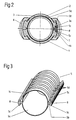
- Figures 2 and 4 show a cross section or longitudinal section through a pipe sleeve M, which consists essentially of the two half-shells 3, 4 with the inserted sealing mat 5 and the locking wedges 6, 7.
- the sealing mat 5 is formed in one piece, open at the axial division point 8 and locked with its two beads 5c in the corresponding undercut grooves 3a, 4a of the end faces of the half-shells 3, 4.
- the sealing mat 5 can, as shown in FIG. 3, be formed in two parts, one half of the half-shell 3 and one of the half-shell 4 being assigned. Accordingly, in Each half of the half shells 3, 4 undercut grooves 3a, 4a are provided for receiving the beads 5c of the sealing mat 5.
- the sealing mat 5 is connected to the bead 5c via an integrally formed web 5b.
- ribs 5d are provided which engage in suitable groove-like depressions in the inner wall of the pipe sleeve and thus prevent the sealing mat 5 from shifting when the pipes 1, 2 are drawn in.
- the two half-shells 3, 4 are connected in a known manner with the locking wedges 6, 7 and pressed onto the pipes 1, 2.
- the required contact pressure is variably adjustable.
- 9 denotes an additional pipe clamp and 10 a locking lug on the half-shell of the pipe socket M.
Landscapes
- Engineering & Computer Science (AREA)
- General Engineering & Computer Science (AREA)
- Mechanical Engineering (AREA)
- Rigid Pipes And Flexible Pipes (AREA)
- Laying Of Electric Cables Or Lines Outside (AREA)
- Joints Allowing Movement (AREA)
- Joints With Sleeves (AREA)
- Dowels (AREA)
- Quick-Acting Or Multi-Walled Pipe Joints (AREA)
- Mechanical Coupling Of Light Guides (AREA)
- Pipe Accessories (AREA)
- Semiconductor Lasers (AREA)
- Cable Accessories (AREA)
- Supports For Pipes And Cables (AREA)
- Branch Pipes, Bends, And The Like (AREA)
- Non-Disconnectible Joints And Screw-Threaded Joints (AREA)
- Joints That Cut Off Fluids, And Hose Joints (AREA)
Description
- Fig. 1
- ein Kabelkanalrohranordnung mit Muffen,
- Fig. 2
- eine Draufsicht auf einen Querschnitt der Muffe,
- Fig. 3
- eine Darstellung der Dichtmatte der Muffe und
- Fig. 4
- eine Draufsicht mit Teillängsschnitt der Muffe.
jeder Hälfte der Halbschalen 3,4 hinterschnittene Nuten 3a,4a für die Aufnahme der Wülste 5c der Dichtmatte 5 vorgesehen. Die Dichtmatte 5 ist, von ihrem zylindrischen Teil 5a ausgehend, über je einen angeformten Steg 5b mit dem Wulst 5c verbunden. Auf der Rückseite des zylindrischen Teiles 5a der Dichtmatte 5 sind Rippen 5d vorgesehen, die in passende rillenartige Vertiefungen in der Innenwand der Rohrmuffe eingreifen und somit ein Verschieben der Dichtmatte 5 beim Einziehen der Rohre 1,2 verhindern. Mit den Verschlußkeilen 6,7 werden die beiden Halbschalen 3,4 in bekannter Weise verbunden und auf die Rohre 1,2 gepreßt. Der erforderliche Anpreßdruck ist variabel einstellbar. Mit 9 ist eine zusätzliche Rohrschelle bezeichnet und mit 10 eine Arretiernase an der Halbschale der Rohrmuffe M.
Claims (3)
- Rohrmuffe (M) aus zwei Halbschalen für Vollrohre und solche. die aus zwei Halbschalen (3,4) zusammengesetzt sind, sogen. Reparaturrohre, wobei eine Dichtung zwischen der abzudichtenden Rohraußenwand und der Muffeninnenwand vorgesehen ist, dadurch gekennzeichnet, daß zwischen abzudichtender Rohraußenwand und Rohrmuffeninnenwand, die die Rohraußenwand umschließende als Dichtmatte (5) ausgebildete Dichtung aus einem Elastomer oder weich eingestellten Thermoplast eingelegt ist, mindestens einmal in Richtung der Rohrachse geteilt ist und mit einem ebenfalls in Längsrichtung angeformten Wulst (5c) formschlüssig in einer hinterschnittenen Nut (3a) einer oder beider Halbschalen (3,4) der Rohrmuffe (M1,M2) verrastet ist.
- Rohrmuffe nach Anspruch 1, dadurch gekennzeichnet, daß die Dichtmatte (5) eine glatte, der abzudichtenden Rohraußenwand zugewandte, Innenfläche (5a) besitzt und auf ihrer Rückseite vorstehende Rippen (5d) aufweist, die in entsprechende Vertiefungen der Rohrmuffeninnenwand eingreifen.
- Rohrmuffe nach Anspruch 1 und 2, dadurch gekennzeichnet, daß die Dichtmatte (5) mittels eines oder zweier schwalbenschwanzförmiger Verschlußkeile (6,7) mit einem dosierbaren Anpreßdruck beaufschlagt ist.
Priority Applications (1)
| Application Number | Priority Date | Filing Date | Title |
|---|---|---|---|
| SI9430188T SI0650007T1 (en) | 1993-10-26 | 1994-08-09 | Tube connecting sleeve |
Applications Claiming Priority (2)
| Application Number | Priority Date | Filing Date | Title |
|---|---|---|---|
| DE4336528 | 1993-10-26 | ||
| DE4336528A DE4336528C2 (de) | 1993-10-26 | 1993-10-26 | Rohrmuffe |
Publications (2)
| Publication Number | Publication Date |
|---|---|
| EP0650007A1 EP0650007A1 (de) | 1995-04-26 |
| EP0650007B1 true EP0650007B1 (de) | 1998-09-23 |
Family
ID=6501063
Family Applications (1)
| Application Number | Title | Priority Date | Filing Date |
|---|---|---|---|
| EP94112448A Expired - Lifetime EP0650007B1 (de) | 1993-10-26 | 1994-08-09 | Rohrmuffe |
Country Status (13)
| Country | Link |
|---|---|
| EP (1) | EP0650007B1 (de) |
| AT (1) | ATE171536T1 (de) |
| CZ (1) | CZ289835B6 (de) |
| DE (2) | DE4336528C2 (de) |
| DK (1) | DK0650007T3 (de) |
| ES (1) | ES2121593T3 (de) |
| HR (1) | HRP940746B1 (de) |
| HU (1) | HU214995B (de) |
| PL (1) | PL176818B1 (de) |
| RO (1) | RO116744B1 (de) |
| RU (1) | RU2085801C1 (de) |
| SI (1) | SI0650007T1 (de) |
| SK (1) | SK282915B6 (de) |
Cited By (5)
| Publication number | Priority date | Publication date | Assignee | Title |
|---|---|---|---|---|
| EP0997678A1 (de) | 1998-10-29 | 2000-05-03 | gabo Systemtechnik GmbH | Klemmmuffenverbindung |
| US6499772B1 (en) | 1998-08-25 | 2002-12-31 | John T. Minemyer | Radial conduit coupling system and method |
| US6505865B2 (en) | 1999-02-05 | 2003-01-14 | John T. Minemyer | Clamshell coupling system and method |
| EP1289087A2 (de) | 2001-08-31 | 2003-03-05 | gabo Systemtechnik GmbH | Verschluss- und Abdichtelement |
| EP2533089A1 (de) | 2011-06-09 | 2012-12-12 | egeplast Werner Strumann GmbH & Co. KG | Einrichtung zur axialen Verbindung von Rohren |
Families Citing this family (15)
| Publication number | Priority date | Publication date | Assignee | Title |
|---|---|---|---|---|
| DE19608352C1 (de) * | 1996-03-05 | 1997-07-24 | Fitr Ges Fuer Innovation Im Ti | Rohrleitung zur Sanierung einer druck- und temperaturbelasteten Rohrleitung und Verfahren und Vorrichtung zum Einbringen in die geschädigte Rohrleitung |
| DE19717751C2 (de) * | 1997-04-21 | 2000-04-06 | Combas Rohrsanierungs Vertrieb | Muffenaußendichtung für Glockenmuffen |
| ATE322646T1 (de) | 2001-05-07 | 2006-04-15 | Elkuch Ganter Wilma | Reparaturrohr |
| DE20215469U1 (de) | 2002-10-09 | 2003-01-09 | Börskens, Christoph, 45257 Essen | Halbschalenmuffe |
| DE102004056859B3 (de) * | 2004-11-25 | 2006-04-27 | Gabo Systemtechnik Gmbh | Verbindungsmuffe |
| PT1849956E (pt) * | 2006-04-26 | 2008-08-22 | Bauer Maschinen Gmbh | Acoplamento de tubagem para elementos tubulares |
| RU2330207C1 (ru) * | 2007-03-26 | 2008-07-27 | Государственное образовательное учреждение высшего профессионального образования Саратовский государственный технический университет | Трубная муфта |
| WO2011043689A1 (ru) * | 2009-10-05 | 2011-04-14 | Zamaleev Firdaus Usmanovich | Муфта с внутренним уплотнением, исключающим отложения (варианты) |
| DE102013011184A1 (de) * | 2013-07-04 | 2015-01-08 | Gabo Systemtechnik Gmbh | Dichtungsmuffe für einen Rohrverband |
| US11103235B2 (en) | 2014-07-08 | 2021-08-31 | Lsi Solutions, Inc. | Rotation adapter and receiver for minimally invasive surgical devices |
| WO2016010455A1 (ru) * | 2014-07-14 | 2016-01-21 | Валерий Владимирович ЮДИН | Универсальная конусная муфта |
| EP3337378B1 (de) * | 2015-08-19 | 2023-06-07 | LSI Solutions, Inc. | Drehadapter und empfänger für minimal invasive chirurgische vorrichtungen |
| CN110541994B (zh) * | 2019-07-16 | 2021-03-30 | 深圳海油工程水下技术有限公司 | 堵漏管卡装置及用于堵漏管卡的锁紧装置 |
| CN111578010A (zh) * | 2020-05-29 | 2020-08-25 | 海盐鸿强五金制造有限公司 | 一种卡扣式消防刚性卡箍 |
| DE102024121224A1 (de) * | 2024-07-25 | 2026-01-29 | Gabo Systemtechnik Gmbh | Verbindungsmuffe, Verbindungsmuffen-Baugruppe, Verbindungsklammer, Verfahren, Mikrorohreinsatz und Dichtmittel zur Verbindung und/oder Reparatur eines Mikrorohrs |
Citations (1)
| Publication number | Priority date | Publication date | Assignee | Title |
|---|---|---|---|---|
| DE7833835U1 (de) * | 1978-11-14 | 1983-07-07 | Thyssen Plastik Anger KG, 8000 München | Rohrmuffe |
Family Cites Families (13)
| Publication number | Priority date | Publication date | Assignee | Title |
|---|---|---|---|---|
| US2899984A (en) * | 1959-08-18 | Gaffin | ||
| DE705322C (de) * | 1936-12-10 | 1941-04-24 | Rosenthal Isolatoren G M B H | Muffenverbindung fuer keramische Rohre, in die blanke elektrische Leiter eingezogen sind |
| US2165920A (en) * | 1938-03-17 | 1939-07-11 | Us Stoneware Co | Pipe joint |
| FR1009262A (fr) * | 1948-05-31 | 1952-05-27 | Le Tube D Acier | Joint de coupure électrique pour canalisations enterrées et branchements domiciliaires |
| GB794580A (en) * | 1955-06-17 | 1958-05-07 | Kirk & Co Tubes Ltd | Improvements in or relating to pipe couplings or the equivalent |
| GB790109A (en) * | 1956-11-12 | 1958-02-05 | Eisenwerke Fried Wilh Duker Ag | Pipe coupling |
| BE759593A (fr) * | 1969-12-03 | 1971-06-01 | Int D Applic De Procedes Ind S | Raccords pour l'accouplement de tuyaux |
| US3711632A (en) * | 1971-12-02 | 1973-01-16 | Gen Motors Corp | End fitting for corrugated conduit |
| US4059291A (en) * | 1974-09-13 | 1977-11-22 | Polva Nederland B. V. | Branch connection |
| GB1491774A (en) * | 1975-09-04 | 1977-11-16 | Montpelier Foundry Pty Ltd | Pipe coupling |
| DE2849380A1 (de) * | 1978-11-14 | 1980-05-22 | Thyssen Plastik Anger Kg | Rohrmuffe |
| US4611835A (en) * | 1984-02-17 | 1986-09-16 | Familian Corp. | Pipe coupling |
| DE4105266A1 (de) * | 1991-02-20 | 1992-08-27 | Kirchner Fraenk Rohr | Rohranschlussteil fuer wellrohre |
-
1993
- 1993-10-26 DE DE4336528A patent/DE4336528C2/de not_active Expired - Fee Related
-
1994
- 1994-08-09 SI SI9430188T patent/SI0650007T1/xx unknown
- 1994-08-09 AT AT94112448T patent/ATE171536T1/de active
- 1994-08-09 ES ES94112448T patent/ES2121593T3/es not_active Expired - Lifetime
- 1994-08-09 DE DE59406965T patent/DE59406965D1/de not_active Expired - Lifetime
- 1994-08-09 DK DK94112448T patent/DK0650007T3/da active
- 1994-08-09 EP EP94112448A patent/EP0650007B1/de not_active Expired - Lifetime
- 1994-08-22 PL PL94304765A patent/PL176818B1/pl unknown
- 1994-10-05 CZ CZ19942441A patent/CZ289835B6/cs not_active IP Right Cessation
- 1994-10-11 SK SK1246-94A patent/SK282915B6/sk not_active IP Right Cessation
- 1994-10-21 RO RO94-01697A patent/RO116744B1/ro unknown
- 1994-10-24 HR HRP4336528.0A patent/HRP940746B1/xx not_active IP Right Cessation
- 1994-10-24 RU RU9494039549A patent/RU2085801C1/ru active
- 1994-10-25 HU HU9403085A patent/HU214995B/hu unknown
Patent Citations (1)
| Publication number | Priority date | Publication date | Assignee | Title |
|---|---|---|---|---|
| DE7833835U1 (de) * | 1978-11-14 | 1983-07-07 | Thyssen Plastik Anger KG, 8000 München | Rohrmuffe |
Cited By (8)
| Publication number | Priority date | Publication date | Assignee | Title |
|---|---|---|---|---|
| US6499772B1 (en) | 1998-08-25 | 2002-12-31 | John T. Minemyer | Radial conduit coupling system and method |
| EP0997678A1 (de) | 1998-10-29 | 2000-05-03 | gabo Systemtechnik GmbH | Klemmmuffenverbindung |
| DE19849941C1 (de) * | 1998-10-29 | 2000-07-13 | Gabo Systemtech Gmbh | Klemmuffenverbindung |
| US6505865B2 (en) | 1999-02-05 | 2003-01-14 | John T. Minemyer | Clamshell coupling system and method |
| US6517122B1 (en) | 1999-02-05 | 2003-02-11 | John T. Minemyer | Clamshell coupling system and method |
| EP1289087A2 (de) | 2001-08-31 | 2003-03-05 | gabo Systemtechnik GmbH | Verschluss- und Abdichtelement |
| EP2533089A1 (de) | 2011-06-09 | 2012-12-12 | egeplast Werner Strumann GmbH & Co. KG | Einrichtung zur axialen Verbindung von Rohren |
| DE102012104920A1 (de) | 2011-06-09 | 2012-12-13 | Egeplast Werner Strumann Gmbh & Co. Kg | Einrichtung zur axialen Verbindung von Rohren |
Also Published As
| Publication number | Publication date |
|---|---|
| HU214995B (hu) | 1998-08-28 |
| SK124694A3 (en) | 1995-05-10 |
| HUT69868A (en) | 1995-09-28 |
| DE59406965D1 (de) | 1998-10-29 |
| DE4336528A1 (de) | 1995-05-04 |
| RU94039549A (ru) | 1996-09-20 |
| PL176818B1 (pl) | 1999-07-30 |
| RO116744B1 (ro) | 2001-05-30 |
| RU2085801C1 (ru) | 1997-07-27 |
| CZ289835B6 (cs) | 2002-04-17 |
| HRP940746A2 (en) | 1996-10-31 |
| CZ244194A3 (en) | 1995-06-14 |
| SI0650007T1 (en) | 1999-02-28 |
| ES2121593T3 (es) | 1998-12-01 |
| DE4336528C2 (de) | 1997-04-24 |
| EP0650007A1 (de) | 1995-04-26 |
| PL304765A1 (en) | 1995-05-02 |
| SK282915B6 (sk) | 2003-01-09 |
| DK0650007T3 (da) | 1999-06-14 |
| ATE171536T1 (de) | 1998-10-15 |
| HU9403085D0 (en) | 1994-12-28 |
| HRP940746B1 (en) | 1997-12-31 |
Similar Documents
| Publication | Publication Date | Title |
|---|---|---|
| EP0650007B1 (de) | Rohrmuffe | |
| DE69603315T2 (de) | Muffenverbindung für Kunststoffrohre | |
| DE69219562T2 (de) | Dichtungsvorrichtung | |
| DE60221577T2 (de) | Rohrkupplung | |
| EP0163252A1 (de) | Rohrverschraubung mit Berührungsdichtung | |
| DE3047867A1 (de) | Rohrverbindung | |
| EP0997678B1 (de) | Klemmmuffenverbindung | |
| DE69511809T2 (de) | Verbindungskupplung für ein Wellrohr | |
| DE3443942A1 (de) | Rohrverbindung mit mindestens einem abzweigstutzen | |
| DE4201799A1 (de) | Anschlussstutzen | |
| DE3525502A1 (de) | Dichtende rohrsteckverbindung | |
| DE8705043U1 (de) | Lösbare Rohrverbindung | |
| EP0042472B1 (de) | Dichtungsanordnung für eine Muffenverbindung | |
| DE9316367U1 (de) | Rohrmuffe | |
| DE4408743A1 (de) | Dichtvorrichtung zum Abdichten von Rohrleitungen | |
| DE19910522C1 (de) | Rohrinnenmuffe mit Manschette und Packer sowie Verfahren zur Innenabdichtung von Rohrleitungen | |
| DE9308181U1 (de) | Anschlußarmatur für Rohre | |
| EP0926417A2 (de) | Rohrpresskupplung für Wellrohre | |
| DE9412445U1 (de) | Unlösbare Rohrverbindung | |
| DE102016101815A1 (de) | "Schwenkverschraubung für ein Einschraubloch mit einer Ansenkung" | |
| DE29616774U1 (de) | Anordnung zur T-förmigen Abzweigung eines Leitungsrohres | |
| EP0617221B1 (de) | Rohrverbindung | |
| DE69419419T2 (de) | Behälter mit durchfluss eines unter druck stehenden fluids, und verfahren zur herstellung eines solchen behälters | |
| EP0392148B1 (de) | Rohrverbindung | |
| EP0486941B1 (de) | Kompensator für Leitungen oder dergleichen |
Legal Events
| Date | Code | Title | Description |
|---|---|---|---|
| PUAI | Public reference made under article 153(3) epc to a published international application that has entered the european phase |
Free format text: ORIGINAL CODE: 0009012 |
|
| AK | Designated contracting states |
Kind code of ref document: A1 Designated state(s): AT BE CH DE DK ES FR GB GR IE IT LI LU MC NL PT SE |
|
| RAX | Requested extension states of the european patent have changed |
Free format text: LT PAYMENT 940902;SI PAYMENT 940902 |
|
| 17P | Request for examination filed |
Effective date: 19950505 |
|
| 17Q | First examination report despatched |
Effective date: 19970326 |
|
| GRAG | Despatch of communication of intention to grant |
Free format text: ORIGINAL CODE: EPIDOS AGRA |
|
| GRAG | Despatch of communication of intention to grant |
Free format text: ORIGINAL CODE: EPIDOS AGRA |
|
| GRAG | Despatch of communication of intention to grant |
Free format text: ORIGINAL CODE: EPIDOS AGRA |
|
| GRAH | Despatch of communication of intention to grant a patent |
Free format text: ORIGINAL CODE: EPIDOS IGRA |
|
| GRAH | Despatch of communication of intention to grant a patent |
Free format text: ORIGINAL CODE: EPIDOS IGRA |
|
| RAP1 | Party data changed (applicant data changed or rights of an application transferred) |
Owner name: GABO SYSTEMTECHNIK GMBH |
|
| GRAA | (expected) grant |
Free format text: ORIGINAL CODE: 0009210 |
|
| AK | Designated contracting states |
Kind code of ref document: B1 Designated state(s): AT BE CH DE DK ES FR GB GR IE IT LI LU MC NL PT SE |
|
| AX | Request for extension of the european patent |
Free format text: LT PAYMENT 940902;SI PAYMENT 940902 |
|
| REF | Corresponds to: |
Ref document number: 171536 Country of ref document: AT Date of ref document: 19981015 Kind code of ref document: T |
|
| REG | Reference to a national code |
Ref country code: CH Ref legal event code: EP |
|
| REF | Corresponds to: |
Ref document number: 59406965 Country of ref document: DE Date of ref document: 19981029 |
|
| REG | Reference to a national code |
Ref country code: CH Ref legal event code: NV Representative=s name: HIEBSCH & PEEGE AG PATENTANWAELTE |
|
| ET | Fr: translation filed | ||
| REG | Reference to a national code |
Ref country code: ES Ref legal event code: FG2A Ref document number: 2121593 Country of ref document: ES Kind code of ref document: T3 |
|
| REG | Reference to a national code |
Ref country code: IE Ref legal event code: FG4D Free format text: GERMAN |
|
| GBT | Gb: translation of ep patent filed (gb section 77(6)(a)/1977) |
Effective date: 19981211 |
|
| REG | Reference to a national code |
Ref country code: PT Ref legal event code: SC4A Free format text: AVAILABILITY OF NATIONAL TRANSLATION Effective date: 19981116 |
|
| REG | Reference to a national code |
Ref country code: DK Ref legal event code: T3 |
|
| PLBE | No opposition filed within time limit |
Free format text: ORIGINAL CODE: 0009261 |
|
| STAA | Information on the status of an ep patent application or granted ep patent |
Free format text: STATUS: NO OPPOSITION FILED WITHIN TIME LIMIT |
|
| 26N | No opposition filed | ||
| PG25 | Lapsed in a contracting state [announced via postgrant information from national office to epo] |
Ref country code: MC Free format text: LAPSE BECAUSE OF NON-PAYMENT OF DUE FEES Effective date: 20000229 |
|
| REG | Reference to a national code |
Ref country code: GB Ref legal event code: IF02 |
|
| REG | Reference to a national code |
Ref country code: SI Ref legal event code: IF |
|
| PGFP | Annual fee paid to national office [announced via postgrant information from national office to epo] |
Ref country code: LU Payment date: 20130826 Year of fee payment: 20 |
|
| PGFP | Annual fee paid to national office [announced via postgrant information from national office to epo] |
Ref country code: GR Payment date: 20130821 Year of fee payment: 20 Ref country code: IE Payment date: 20130819 Year of fee payment: 20 Ref country code: NL Payment date: 20130822 Year of fee payment: 20 Ref country code: ES Payment date: 20130828 Year of fee payment: 20 Ref country code: AT Payment date: 20130821 Year of fee payment: 20 Ref country code: CH Payment date: 20130826 Year of fee payment: 20 Ref country code: DE Payment date: 20130702 Year of fee payment: 20 Ref country code: DK Payment date: 20130819 Year of fee payment: 20 Ref country code: PT Payment date: 20130211 Year of fee payment: 20 Ref country code: SE Payment date: 20130822 Year of fee payment: 20 |
|
| PGFP | Annual fee paid to national office [announced via postgrant information from national office to epo] |
Ref country code: GB Payment date: 20130823 Year of fee payment: 20 Ref country code: FR Payment date: 20130820 Year of fee payment: 20 |
|
| PGFP | Annual fee paid to national office [announced via postgrant information from national office to epo] |
Ref country code: IT Payment date: 20130823 Year of fee payment: 20 |
|
| PGFP | Annual fee paid to national office [announced via postgrant information from national office to epo] |
Ref country code: BE Payment date: 20130821 Year of fee payment: 20 |
|
| REG | Reference to a national code |
Ref country code: DK Ref legal event code: EUP Effective date: 20140809 |
|
| REG | Reference to a national code |
Ref country code: DE Ref legal event code: R071 Ref document number: 59406965 Country of ref document: DE |
|
| REG | Reference to a national code |
Ref country code: CH Ref legal event code: PL |
|
| REG | Reference to a national code |
Ref country code: NL Ref legal event code: V4 Effective date: 20140809 Ref country code: PT Ref legal event code: MM4A Free format text: MAXIMUM VALIDITY LIMIT REACHED Effective date: 20140809 |
|
| BE20 | Be: patent expired |
Owner name: *GABO SYSTEMTECHNIK G.M.B.H. Effective date: 20140809 |
|
| REG | Reference to a national code |
Ref country code: GB Ref legal event code: PE20 Expiry date: 20140808 |
|
| REG | Reference to a national code |
Ref country code: AT Ref legal event code: MK07 Ref document number: 171536 Country of ref document: AT Kind code of ref document: T Effective date: 20140809 |
|
| REG | Reference to a national code |
Ref country code: IE Ref legal event code: MK9A |
|
| REG | Reference to a national code |
Ref country code: SE Ref legal event code: EUG |
|
| REG | Reference to a national code |
Ref country code: GR Ref legal event code: MA Ref document number: 980402911 Country of ref document: GR Effective date: 20140810 |
|
| PG25 | Lapsed in a contracting state [announced via postgrant information from national office to epo] |
Ref country code: DE Free format text: LAPSE BECAUSE OF EXPIRATION OF PROTECTION Effective date: 20140812 Ref country code: IE Free format text: LAPSE BECAUSE OF EXPIRATION OF PROTECTION Effective date: 20140809 |
|
| REG | Reference to a national code |
Ref country code: ES Ref legal event code: FD2A Effective date: 20141120 |
|
| PG25 | Lapsed in a contracting state [announced via postgrant information from national office to epo] |
Ref country code: GB Free format text: LAPSE BECAUSE OF EXPIRATION OF PROTECTION Effective date: 20140808 |
|
| PG25 | Lapsed in a contracting state [announced via postgrant information from national office to epo] |
Ref country code: PT Free format text: LAPSE BECAUSE OF EXPIRATION OF PROTECTION Effective date: 20140820 |
|
| PG25 | Lapsed in a contracting state [announced via postgrant information from national office to epo] |
Ref country code: ES Free format text: LAPSE BECAUSE OF EXPIRATION OF PROTECTION Effective date: 20140810 |