EP0648059B1 - Picture data compression device having color-sensitive quantization - Google Patents
Picture data compression device having color-sensitive quantization Download PDFInfo
- Publication number
- EP0648059B1 EP0648059B1 EP19940306568 EP94306568A EP0648059B1 EP 0648059 B1 EP0648059 B1 EP 0648059B1 EP 19940306568 EP19940306568 EP 19940306568 EP 94306568 A EP94306568 A EP 94306568A EP 0648059 B1 EP0648059 B1 EP 0648059B1
- Authority
- EP
- European Patent Office
- Prior art keywords
- data
- red
- block
- circuit
- bit
- Prior art date
- Legal status (The legal status is an assumption and is not a legal conclusion. Google has not performed a legal analysis and makes no representation as to the accuracy of the status listed.)
- Expired - Lifetime
Links
Images


Classifications
-
- H—ELECTRICITY
- H04—ELECTRIC COMMUNICATION TECHNIQUE
- H04N—PICTORIAL COMMUNICATION, e.g. TELEVISION
- H04N11/00—Colour television systems
- H04N11/04—Colour television systems using pulse code modulation
- H04N11/042—Codec means
- H04N11/044—Codec means involving transform coding
-
- H—ELECTRICITY
- H04—ELECTRIC COMMUNICATION TECHNIQUE
- H04N—PICTORIAL COMMUNICATION, e.g. TELEVISION
- H04N19/00—Methods or arrangements for coding, decoding, compressing or decompressing digital video signals
- H04N19/10—Methods or arrangements for coding, decoding, compressing or decompressing digital video signals using adaptive coding
- H04N19/102—Methods or arrangements for coding, decoding, compressing or decompressing digital video signals using adaptive coding characterised by the element, parameter or selection affected or controlled by the adaptive coding
- H04N19/124—Quantisation
-
- H—ELECTRICITY
- H04—ELECTRIC COMMUNICATION TECHNIQUE
- H04N—PICTORIAL COMMUNICATION, e.g. TELEVISION
- H04N19/00—Methods or arrangements for coding, decoding, compressing or decompressing digital video signals
- H04N19/10—Methods or arrangements for coding, decoding, compressing or decompressing digital video signals using adaptive coding
- H04N19/102—Methods or arrangements for coding, decoding, compressing or decompressing digital video signals using adaptive coding characterised by the element, parameter or selection affected or controlled by the adaptive coding
- H04N19/12—Selection from among a plurality of transforms or standards, e.g. selection between discrete cosine transform [DCT] and sub-band transform or selection between H.263 and H.264
- H04N19/122—Selection of transform size, e.g. 8x8 or 2x4x8 DCT; Selection of sub-band transforms of varying structure or type
-
- H—ELECTRICITY
- H04—ELECTRIC COMMUNICATION TECHNIQUE
- H04N—PICTORIAL COMMUNICATION, e.g. TELEVISION
- H04N19/00—Methods or arrangements for coding, decoding, compressing or decompressing digital video signals
- H04N19/10—Methods or arrangements for coding, decoding, compressing or decompressing digital video signals using adaptive coding
- H04N19/102—Methods or arrangements for coding, decoding, compressing or decompressing digital video signals using adaptive coding characterised by the element, parameter or selection affected or controlled by the adaptive coding
- H04N19/124—Quantisation
- H04N19/126—Details of normalisation or weighting functions, e.g. normalisation matrices or variable uniform quantisers
-
- H—ELECTRICITY
- H04—ELECTRIC COMMUNICATION TECHNIQUE
- H04N—PICTORIAL COMMUNICATION, e.g. TELEVISION
- H04N19/00—Methods or arrangements for coding, decoding, compressing or decompressing digital video signals
- H04N19/10—Methods or arrangements for coding, decoding, compressing or decompressing digital video signals using adaptive coding
- H04N19/134—Methods or arrangements for coding, decoding, compressing or decompressing digital video signals using adaptive coding characterised by the element, parameter or criterion affecting or controlling the adaptive coding
- H04N19/136—Incoming video signal characteristics or properties
- H04N19/137—Motion inside a coding unit, e.g. average field, frame or block difference
-
- H—ELECTRICITY
- H04—ELECTRIC COMMUNICATION TECHNIQUE
- H04N—PICTORIAL COMMUNICATION, e.g. TELEVISION
- H04N19/00—Methods or arrangements for coding, decoding, compressing or decompressing digital video signals
- H04N19/10—Methods or arrangements for coding, decoding, compressing or decompressing digital video signals using adaptive coding
- H04N19/134—Methods or arrangements for coding, decoding, compressing or decompressing digital video signals using adaptive coding characterised by the element, parameter or criterion affecting or controlling the adaptive coding
- H04N19/136—Incoming video signal characteristics or properties
- H04N19/14—Coding unit complexity, e.g. amount of activity or edge presence estimation
-
- H—ELECTRICITY
- H04—ELECTRIC COMMUNICATION TECHNIQUE
- H04N—PICTORIAL COMMUNICATION, e.g. TELEVISION
- H04N19/00—Methods or arrangements for coding, decoding, compressing or decompressing digital video signals
- H04N19/10—Methods or arrangements for coding, decoding, compressing or decompressing digital video signals using adaptive coding
- H04N19/134—Methods or arrangements for coding, decoding, compressing or decompressing digital video signals using adaptive coding characterised by the element, parameter or criterion affecting or controlling the adaptive coding
- H04N19/146—Data rate or code amount at the encoder output
- H04N19/149—Data rate or code amount at the encoder output by estimating the code amount by means of a model, e.g. mathematical model or statistical model
-
- H—ELECTRICITY
- H04—ELECTRIC COMMUNICATION TECHNIQUE
- H04N—PICTORIAL COMMUNICATION, e.g. TELEVISION
- H04N19/00—Methods or arrangements for coding, decoding, compressing or decompressing digital video signals
- H04N19/10—Methods or arrangements for coding, decoding, compressing or decompressing digital video signals using adaptive coding
- H04N19/169—Methods or arrangements for coding, decoding, compressing or decompressing digital video signals using adaptive coding characterised by the coding unit, i.e. the structural portion or semantic portion of the video signal being the object or the subject of the adaptive coding
- H04N19/17—Methods or arrangements for coding, decoding, compressing or decompressing digital video signals using adaptive coding characterised by the coding unit, i.e. the structural portion or semantic portion of the video signal being the object or the subject of the adaptive coding the unit being an image region, e.g. an object
- H04N19/176—Methods or arrangements for coding, decoding, compressing or decompressing digital video signals using adaptive coding characterised by the coding unit, i.e. the structural portion or semantic portion of the video signal being the object or the subject of the adaptive coding the unit being an image region, e.g. an object the region being a block, e.g. a macroblock
-
- H—ELECTRICITY
- H04—ELECTRIC COMMUNICATION TECHNIQUE
- H04N—PICTORIAL COMMUNICATION, e.g. TELEVISION
- H04N19/00—Methods or arrangements for coding, decoding, compressing or decompressing digital video signals
- H04N19/10—Methods or arrangements for coding, decoding, compressing or decompressing digital video signals using adaptive coding
- H04N19/169—Methods or arrangements for coding, decoding, compressing or decompressing digital video signals using adaptive coding characterised by the coding unit, i.e. the structural portion or semantic portion of the video signal being the object or the subject of the adaptive coding
- H04N19/186—Methods or arrangements for coding, decoding, compressing or decompressing digital video signals using adaptive coding characterised by the coding unit, i.e. the structural portion or semantic portion of the video signal being the object or the subject of the adaptive coding the unit being a colour or a chrominance component
-
- H—ELECTRICITY
- H04—ELECTRIC COMMUNICATION TECHNIQUE
- H04N—PICTORIAL COMMUNICATION, e.g. TELEVISION
- H04N9/00—Details of colour television systems
- H04N9/79—Processing of colour television signals in connection with recording
- H04N9/80—Transformation of the television signal for recording, e.g. modulation, frequency changing; Inverse transformation for playback
- H04N9/804—Transformation of the television signal for recording, e.g. modulation, frequency changing; Inverse transformation for playback involving pulse code modulation of the colour picture signal components
- H04N9/8042—Transformation of the television signal for recording, e.g. modulation, frequency changing; Inverse transformation for playback involving pulse code modulation of the colour picture signal components involving data reduction
- H04N9/8047—Transformation of the television signal for recording, e.g. modulation, frequency changing; Inverse transformation for playback involving pulse code modulation of the colour picture signal components involving data reduction using transform coding
Definitions
- This invention relates to picture data compressing devices which may advantageously be employed, for example, in equipment handling compressed picture data, such as digital video tape recorders (VTRs), television telephone systems, teleconference systems or transmitters for telecasting stations, and to red data detection devices which may, for example, be employed in such picture data compressing apparatus.
- VTRs digital video tape recorders
- red data detection devices which may, for example, be employed in such picture data compressing apparatus.
- the A/D converter 51 digitizes the audio signals to generate audio data which is supplied to an audio recording processing circuit 52 which then processes the audio data into a form suitable for recording and transmits the processed audio data to an error correction encoding circuit 61.
- the A/D converter 54 digitizes the picture signals by, for example, frame-based sampling, to generate component data, that is luminance data (Y data) and two color difference data (R-Y data and B-Y data), and transmits the component data to a blocking circuit 56 within a compression encoding circuit 55.
- the blocking circuit 56 divides each of the Y-data, R-Y data and the B-Y data into blocks each consisting of a matrix of 8 vertically arrayed pixels and 8 horizontally arrayed pixels (DCT blocks), these blocks being routed to a shuffling circuit 57.
- the shuffling circuit 57 generates a single macro-block from 8 DCT blocks, namely 6 Y data blocks, 1 R-Y data block and 1 B-Y data block. These 8 blocks are data located at the same location on a picture.
- the shuffling circuit 57 effects pre-set shuffling on the macro-block basis and generates a single unit from five macro-blocks and outputs data on the unit basis.
- the unit picture data is supplied to a discrete cosine transform (DCT) circuit 58.
- DCT discrete cosine transform
- the DCT circuit 58 transforms the picture data of each macro-block making up the unit from data on the time scale into that on the frequency scale, and routes the transform coefficients to a quantization circuit 59.
- the quantization circuit 59 selects such quantization coefficients which will give a fixed data length of the unit picture data outputted from a variable length encoding circuit 60 as later explained, and re-quantizes the unit-based picture data with the aid of these quantization coefficients.
- the unit-based picture data thus re-quantized is supplied to the variable length encoding circuit 60.
- variable length coding circuit 60 processes the unit-based data into fixed-length data so that the data quantity of the picture data is not more than a pre-set quantity, and routes the resulting fixed-length data to the error correction coding combining circuit 61.
- the error correction coding combining circuit 61 combines the unit-based picture data having the fixed length with the audio data supplied from the audio data recording processing circuit 52 to generate recording data.
- the error correction encoding combining circuit 61 appends so-called parity data for error correction to the recording data and routes the resulting signals to a recording modulation circuit 62.
- the recording modulation circuit 62 modulates the recording data from the combining operation in a pre-set manner and routes the resulting modulated signals to a recording head 63.
- the recording head 63 records the picture data obliquely on a video tape, not shown.
- the above-mentioned digital VTR has a drawback that, since the picture data are divided into plural macro-blocks and processed with DCT or re-quantization or the like on the macro-block basis, there arises the risk of occurrence of so-called block distortion, in which the noise is produced at a junction between macro-blocks on the reproduced picture. Above all, the block distortion of a macro-block containing a large quantity of red-hued picture data tends to be visually outstanding, and thus has been desired to be improved.
- EP-A-0 580 101 discloses a picture compression device according to the pre-characterising part of claim 1 hereof.
- the present invention provides a picture compression device comprising:
- control means variably controls the quantization step of the quantization means so that the quantization step will become finer if the block is detected as being a red-hued block.
- control means variably controls the quantization step of the quantization means quantizing red data so that the quantization step will become finer for a macro-block consisting of a luminance data block and two color data blocks.
- control means performs activity-based classing for a pre-set number of macro-blocks as a processing unit, and adaptively controls the quantization steps of the quantization means according to classes so that such class is selected in which the quantization step of the quantization means quantizing red-hued data is finest if the block from the blocking means is found to be the red-hued block by the red block detection means.
- a preferred form of implementation of the invention described hereinbelow provides a picture data compressing apparatus in which the above-mentioned block distortion containing a large quantity of the red-hued picture data is diminished, thereby contributing to improvement in the picture quality.
- the preferred form of implementation of the invention has a red data detecting device including upper bit extracting means for extracting upper three bits of red-hued data supplied as 8-bit bi-level data and outputting the extracted upper three bits, threshold date outputting means for outputting, as threshold data, upper three bits of 8-bit bi-level data that is closest to a reference value employed in detecting red data and that may be divided out by a power of 2, where an exponent is a natural number, and comparator means for comparing red-hued data from the upper bit extracting means to threshold data from the threshold data outputting means.
- the comparator means outputs high-level red detection data indicating that the picture data is the red data or the low level red detection data indicating that the picture data is not red data when the red data is larger or smaller than the threshold data, respectively.
- the red data detecting device may include upper most bit extracting means for extracting upper three bits of blue-hued data supplied as 8-bit bi-level data and outputting the extracted upper three bits, inverting means for inverting an upper most bit of low level blue-hued data indicating that the picture data is the red data when the upper most bit is supplied from the upper most bit extracting means and outputting the inverted data as a high level red detection data and for inverting an upper most bit of high level blue-hued data indicating that the picture data is not the red data when the upper most bit is supplied from the upper most bit extracting means and outputting the inverted data as a low level red detection data, and red data detection means for outputting high-level red detection data indicating that picture data is red data only when high-level red detection data is supplied from the comparator means at the same time as high-level red detection data is supplied from the inverting means.
- the threshold data outputting means may output upper three bits of bi-level data for 160 which is an 8-bit bi-level data that may be divided by some power of 2, where an exponent is a natural number, as the threshold data, and, if the picture data is red-hued picture data, the blue-hued color data has a value not more than 128 where 1 stands only at the upper most bit of the 8-bit blue color data, the upper most bit extracting means extracts the upper most bit from the 8-bit blue-hued data for outputting low-level blue-hued data indicating that the picture data is the red hued data by extracting the upper most bit from the 8-bit blue-hued data or outputting high level blue-hued data indicating that the picture data is not red picture data.
- a preferred form of implementation of the invention described hereinbelow provides a red data detection device in which the number of bits required in determining whether or not the picture data is red-hued may be reduced, thereby enabling simplification of the hardware.
- the present invention also provides a red data detecting device comprising upper bit extracting means for extracting upper three bits of red-hued data supplied as 8-bit bi-level data and outputting the extracted upper three bits, and threshold date outputting means for outputting, as threshold data, upper three bits of 8-bit bi-level data that is closest to a reference value in detecting red data and that may be divided out by a power of 2, where an exponent is a natural number.
- the red data detecting device also includes comparator means which is adapted for comparing red-hued data from the upper bit extracting means to the threshold data from the threshold data outputting means and for outputting high-level red detection data indicating that the picture data is the red data or the low level red detection data indicating that the picture data is not red data when the red data is larger or smaller than the threshold data, respectively.
- the red data detecting device additionally includes upper most bit extracting means for extracting the upper most bit of blue-hued data supplied as 8-bit bi-level data and outputting the extracted upper most bit, and inverting means for complementing an upper most bit of low level blue-hued data indicating that the picture data is the red data when the upper most bit is supplied from the upper most bit extracting means and outputting the complemented data as a high level red detection data, and for complementing an upper most bit of high level blue-hued data indicating that the picture data is not the red data when the upper most bit is supplied from the upper most bit extracting means and outputting the inverted data as a low level red detection data.
- upper most bit extracting means for extracting the upper most bit of blue-hued data supplied as 8-bit bi-level data and outputting the extracted upper most bit
- inverting means for complementing an upper most bit of low level blue-hued data indicating that the picture data is the red data when the upper most bit is supplied from the upper most
- the red data detecting device finally includes red data detection means for outputting high-level red detection data indicating that picture data is red data only when high-level red detection data is supplied from the comparator means at the same time as high-level red detection data is supplied from the inverting means, and a red block discrimination data outputting means having its count value reset for each of pre-set units of picture data and having its count value set to a power of 2, where an exponent is a natural number.
- the red block decision data outputting means counts the high level red detection data from the red data detection means for each of the pre-set units of picture data and outputs red block decision data indicating that the pre-set unit of picture data is red picture data when the count value of the red detection data reaches the pre-set count value.
- the blocking means divides supplied picture data into plural blocks each consisting of a pre-set number of pixels, and routes the blocked data to transform encoding means and red block detection means.
- the transform encoding means transform encode the picture data from the blocking means on the block basis to generate transform coefficients which are routed to the quantization means.
- the quantization means re-quantize block-based picture data supplied from the transform encoding means. If the red block detecting means detect that the block is the red block, the control means variably controls the quantization step of the R-Y data in the quantization means so that the quantization step in the quantization means will be finer, thereby enabling it to finely re-quantize picture data of the red block.
- the red data detection device discriminates whether or not the picture data is red picture data based upon the red hued data among the luminance data and two color data, that is red-hued data and blue-hued data, formed from the picture data.
- the upper bit extraction means extract upper three bits of the red-hued data supplied as 8-bit bi-level data and routes the extracted data to comparator means. That is, the upper bit extraction means extracts fifth to seventh bits from among red-hued data supplied as the 0th to 7th bits, totalling at 8 bits, and routes the extracted bits to the comparator means.
- the threshold data outputting means routes to the comparator means threshold data corresponding to upper three bits from among 8-bit bi-level data which is closest to a reference value in detecting red data and which is represented by some power of 2, where an exponent is a natural number.
- a value in the neighborhood of 170 is desirable as a reference value in detecting red data.
- the 8-bit bi-level data that may be divided out by some power of 2 and that is closest to 170 is 160 which may be divided out by 2 5 .
- 160 is represented in 8 bits as "10100000" in which 0s are arrayed next to upper three bits.
- the binary data smaller than 160 (0 to 159) is "00000000" to "10011111", with the upper three bits being necessarily smaller than 101. This indicates that red-hued data can be detected only with the upper three bits.
- the threshold data outputting means output only the upper three bits, namely "101", of the 8-bit bi-level data "10100000", to the comparator means as the above-mentioned threshold data.
- the comparator means compares the red-hued data from the upper bit extracting means to threshold data from the threshold data outputting means. If the red-hued data is larger than the threshold data, the comparator means outputs high-level red detection data indicating that the picture data is red data. Conversely, if the red-hued data is smaller than the threshold data, the comparator means outputs low-level red detection data indicating that the picture data is not red data.
- the picture data is highly likely to be red data, so that the comparator means outputs high-level red detection data. Conversely, if the upper three bits of the red-hued data is less than "101", the picture data is hardly likely to be red data, so that the comparator means outputs low-level red detection data.
- the threshold data is 175, it is necessary to compare the threshold data for 175, that is "10100111", to the above-mentioned 8-bit red-hued data, so that 8-bit comparator means is required.
- the threshold data so as to be a value that may be divided out by some power of 2
- the red detection device may be provided in, for example, a digital VTR in which DCT processing and re-quantization, for example, are carried out on the macro-block basis, so that, if the macro-block is found to be replete with red picture data, the quantization step may be refined for re-quantization, thereby alleviating the so-called block distortion for improving the picture quality
- the picture data is determined to be red data or not based only on the gradation values of red-hued data, some detection error is produced.
- red data detection device whether or not certain picture data is red picture data is determined based upon blue-hued data as well, and the result of decision with the red-hued data is combined with the result of decision with the blue-hued data in order to determined whether or not the picture data is red picture data.
- the red data detection device extracts only the upper most bit of the blue-hued data supplied as 8-bit bi-level data.
- the reason is that 128, for example, is desirable as a reference value if whether or not the picture data is red data is to be determined with the use of the blue-hued data.
- 128 may be divided out by 2 4 and may be represented with 8-bit bi-level data as "10000000". Consequently, in determining whether or not the picture data is red data with the use of the blue-hued data, it suffices if it is determined whether the upper most bit of the blue-hued data is "1" or "0".
- the upper most bit extracting means extracts and outputs only the upper most bit of he blue-hued data supplied as the 8-bit bi-level data.
- the blue-hued data has the gradation value of 128 or less.
- the picture data with blue-hued data having the gradation value in excess of 128 is not red picture data. For this reason, if the picture data is red picture data, the upper most bit extraction means outputs low-level data, whereas, if the picture data is not red picture data, the upper most bit extraction means outputs high-level data.
- the inverting means complement data from the upper most bit extracting means, and transmit the complemented data as red detection data to the red detection means.
- the red detection means outputs high-level red detection data indicating that the picture data is red data only when the high-level red detection data is supplied from the comparator means and simultaneously the high-level red detection data is supplied from the inverting means.
- the red data detection means take the picture data as being red picture data when the red-hued data has the gradation value in excess of 160 and the blue-hued data has the gradation value of 128 or less, and outputs the above-mentioned high-level red detection data.
- red data detection may be achieved more accurately.
- the threshold value of the blue-hued data so as to be divisible by some powers of 2
- the number of bits required for discrimination can be diminished, for example, it can be diminished to one if the threshold value is 128.
- 16 bits required for discrimination with the use of 8 bits each of the red-hued data and the blue-hued data can now be reduced to three bits for the red-hued data and to one bit for the blue-hued data, thus totalling at four bits, thereby simplifying the hardware and lowering the cost.
- the red data detection device counts the number of red picture data on the basis of a pre-set processing unit, such as a macro-block, and determines the picture data of such pre-set processing unit to be red picture data when a number of the red picture data in excess of a pre-set value exists in the processing unit.
- the red data detection device routes red detection data from red data detection means detecting whether or not the picture data is red picture data to red block discrimination data outputting means based upon the red-hued data and the blue-hued data as described above.
- the red block discrimination data outputting means is a counter having the capacity of counting up to a certain power of 2, with an exponent being a natural number, for example, a 3-bit counter capable of counting the numbers of from 0 to 7. It is reset for each pre-set processing unit, for example, for each macro-block.
- the red block discrimination data outputting means counts the number of high-level red detection data from the red data detection means. If a number of the high-level red detection data not less than eight is supplied within a time period for one macro-block, the counter outputs red block discrimination data indicating that the macro-block is the red macro-block.
- the picture data of the red-hued blocks may be improved in reproducibility.
- the picture data of the red-hued blocks by re-quantizing the picture data of the red-hued blocks with finer quantization steps on detection of such red-hued blocks, the picture data of the red-hued blocks, otherwise affecting the remaining blocks, that is Y-data and B-Y data blocks, may be improved in reproducibility. The result is that block distortion in the reproduced picture of the red-hued picture data may be diminished to contribute to the improved quality of the reproduced picture.
- the red data detection device sets the threshold value for detection of whether or not the picture data is red picture data to a value divisible by powers of 2, as described above, the number of bits necessary for discrimination may be diminished, thus simplifying the hardware and lowering the cost.
- the red detection data used in determining whether or not the picture data is the red picture data is counted using a counter having the capacity of counting up to a pre-set power of 2, the number of the counter stages may be diminished, while red block decision is enabled on the basis of a pre-set processing unit.
- the picture data is the red picture data, so that, by providing the red data detection device in a digital VTR executing DCT processing or re-quantization on the basis of a pre-set processing unit, and by refining the quantization steps for re-quantization if it is found that the picture of the pre-set processing unit contains a pre-set larger quantity of red picture data, it becomes possible to alleviate the block distortion to contribute to the improved picture quality.
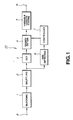
- a picture data compressing device embodying the invention includes a blocking circuit 1, as blocking means for dividing picture data into blocks each consisting of a pre-set number of pixels, and a shuffling circuit 2 for shuffling the picture data blocked by the blocking circuit 1, as shown for example in Fig.1.
- the picture data compressing device also includes a discrete cosine transform (DCT) circuit 3 as transform encoding means for orthogonal transforming the shuffled picture data for conversion into data on the frequency domain and outputting the resulting transform coefficients, a quantization circuit 4 as quantization means for re-quantizing the transform coefficients, and a variable length encoding circuit 5 for providing a fixed data word length for picture data from the quantization circuit 4.
- DCT discrete cosine transform
- the picture data compressing device includes a red hue detector 6 for detecting a block of picture data supplied from the shuffling circuit 2 as being a red-hued block when it has a number of red-hued pixels in excess of a pre-set number, and a controller 7 as controlling means for refining the quantization steps of the quantization circuit 4 when the block has been detected as being a red-hued block by the red-hue detector 6.
- the red-hue detector 6, embodying the present invention detects whether or not a given macro-block is a red-hued macro-block, from one macro-block to another, based on the R-Y data and the B-Y data among the luminance data (Y data), red color data (R-Y data) and the blue color data (B-Y data), produced from the three color picture data.
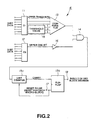
- the red-hued detector is constructed for example as shown in Fig.2.
- the red-hue detector 6 has a red data extraction circuit 11 for extracting and outputting upper three bits from the R-Y data supplied as 8-bit bi-level data and a blue data extraction circuit 12 for extracting and outputting only the upper most bit from the R-Y data supplied as 8-bit bi-level data, as shown in Fig.2.
- the red detector 6 includes a threshold value data outputting circuit 15 for extracting upper three bits of the 8-bit bi-level data which may be divided out by a power of 2 and which is closest to a number employed as a reference value in detecting the red data, where the exponent is a natural number, and a comparator 13 for comparing the threshold value data with the R-Y data from the red data extraction circuit 11.
- the red detector 16 also includes an inverter for complementing the upper most bit of the B-Y data from the blue data extraction circuit 12, and an AND gate 14 for outputting a high-level red detection data when the comparison output of the comparator 13 and the output of the inverter 16 are both at a high level. Furthermore, the red detector 6 includes a 3-bit counter 19a for counting the high-level red detection data from the AND gate 14 from 0 to 7, and a flip-flop 19b which is reset on the macro-block basis and which outputs a red block decision data indicating that the current macro-block is a red macro-block when there is supplied a carry outputted by the 3-bit counter 9a having counted 8 high-level red detection data.
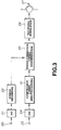
- the above-described picture data compressing device embodying the present invention is employed as a compression encoding circuit 10 in the recording system of the digital VTR as shown for example in Fig.3.
- an analog audio signal is supplied via an input terminal 20 to an A/D converter 21, while an analog picture signal is supplied via an input terminal 23 to an A/D converter 24.
- the A/D converter 21 formulates audio data by digitizing the audio signals to transmit the audio data to an audio recording processing circuit 22.
- the audio recording processing circuit 22 modifies the audio data into a form suitable for recording and routes the modified data to an error correction coding combining circuit 25.
- the A/D converter 24 digitizes the picture signals by sampling using sampling clocks having a pre-set frequency to generate component data, that is luminance data (Y data) and two color difference data (R-Y data and B-Y data), and transmits the component data to the compression coding circuit 10 which is the picture data compressing device embodying the present invention.
- the above-mentioned component data is supplied to he blocking circuit 1 via input terminal 8 of the compression coding circuit 10 shown in Fig.1.
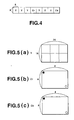
- the blocking circuit 56 generates DCT blocks each consisting of 64 blocks, arranged in a matrix of 8 vertically arrayed pixels and 8 horizontally arrayed pixels, from the Y-data, R-Y data and the B-Y data of the same region, as shown for example in Fig.4. From the eight DCT blocks, that is six DCT blocks of the Y-data, shown in Fig.5a, one DCT block of the R-Y data, shown in Fig.5b and one DCT block of the B-Y data, shown in Fig.5c, one macro-block is formed and outputted. The eight DCT blocks making up such macro-block should be data located on the same screen region. The picture data of the macro-block is supplied to the shuffling circuit 2.
- the shuffling circuit 2 shuffles data on the macro-block basis in a predetermined manner and outputs five of the thus shuffled macro-blocks as a lump, that is a unit.
- the picture data outputted on the unit basis are supplied to the DCT circuit 3 and the red detector 6.
- the picture data outputted on the unit basis is supplied to the DCT circuit 3 and to the red detector 6.
- the DCT circuit 3 transforms the picture data (Y data, R-Y data and B-Y data) of each DCT block of each of the five macro-blocks making up each unit into data on the frequency scale and routes the transform coefficients to the quantization circuit 4.
- the quantization circuit 4 re-quantizes the transform coefficients of the Y data, R-Y data and B-Y data for compressing the picture data and outputting the compressed picture data.
- the red detector 6 has a construction as shown in Fig.2, in which the R-Y data is supplied to a red data extraction circuit 11 and the B-Y data is supplied to a blue data extraction circuit 12.
- a straight line drawn from a point of approximately 0.02 on the X-axis and approximately 0.44 on the Y-axis to a point of approximately 0.42 on the X-axis and approximately 0.56 on the Y-axis represents an axis of the R-Y data.
- a straight line drawn from a point of approximately 0.42 on the X-axis and approximately 0.56 on the Y-axis to a point of approximately 0.16 on the X-axis and 0 on the Y-axis represents an axis of the B-Y data.
- the axis of the R-Y data is divided into 256 gradations, tnat is 0th to 255th gradation, where a point indicated by approximately 0.02 on the X-axis and approximately 0.44 on the Y-axis is the 0th gradation and a point indicated by approximately 0.6 on the X-axis and approximately 0.2 on the Y-axis is the 255th gradation, and that the axis of the B-Y data is divided into 256 gradations, that is 0th to 255th gradient, where a point indicated by approximately 0.42 on the X-axis and approximately 0.56 on the Y-axis is the 0th gradation and a point indicated by approximately 0.16 on the X-axis and 0 on the Y-axis is the 255nm gradation.
- the red detector 6 detects R-Y data of the pixels of not lower than the 170th gradation from among the R-Y data of 64 pixels making up each DCT block and transmits the detected output to the controller 7, while also detecting B-Y data of the pixels of not higher than the 128th gradation from among the B-Y data of the 64 pixels making up each DCT block and transmits the detected output to the controller 7.
- the 8-bit bi-level data which can be divided out by a power of 2 and which becomes closest to 170 is 160, that is 160 can be divided out by 2 5 .
- 160 is "10100000", in which "0" appears at each of the bits lower than the upper three bits.
- 0 to 159 (numbers smaller than 160) is "00000000"to "10011111", that is, the values of upper three bits necessarily become 101 or larger. This indicates that red data can be detected from the upper three bits of the 8-bit R-Y data.
- the red data extraction circuit 11 of the red detector 6 extracts the upper three bits, namely the fifth to seventh bits, from among the 8-bit R-Y data, namely 0th to 7th bits, and routes these upper three bits to the comparator 13.
- the threshold data outputting circuit 15 routes the upper three bits "101" of the 8-bit bi-level data "10100000", which is equal to 160, to the comparator 13, as threshold data.
- the comparator 13 compares the 3-bit R-Y data from the red data extraction circuit 11 to the 3-bit threshold data from the threshold data outputting circuit 15. If the R-Y data is larger than the threshold data, the comparator 13 outputs high level red detection data indicating that the picture data is red data to an AND gate 14. Conversely, if the R-Y data is lesser than the threshold data, the comparator 13 outputs low level red detection data indicating that the picture data is not red data to the AND gate 14.
- the picture data is highly likely to be red in hue, so that the comparator 13 outputs high-level red detection data to the AND gate 14. Conversely, if the upper three bits of the R-Y data is less than "101", the picture data is not likely to be red in hue, so that the comparator 13 outputs low-level red detection data to the AND gate 14.
- the 8-bit bi-level data which can be divided out by a power of 2 and which becomes closest to 128 is 128, that is 128 can be divided out by 2 5 . If represented with 8 bits, 128 is "10000000", in which "0" appears at each of the bits lower than the upper most bit. This indicates that red data can be detected only from the upper most one bit.
- the blue data extracting circuit 12 extracts only the upper most bit from the B-Y data supplied as the 8-bit bi-level data, and transmits the extracted upper most bit to the inverter 16.
- the B-Y data has the gradation lower than 128. That is, the picture data having the B-Y data having the gradation not lower than 128 is not red data. Consequently, if the picture data is the red picture data, the blue data extraction circuit 12 outputs a low-level data and, if otherwise, the blue data extraction circuit 12 outputs a high-level data.
- the inverter complements the upper most bit of the B-Y data from the blue data extraction circuit 12 and routes the complemented data as red detection data to the AND gate 14.
- the AND gate 14 outputs high-level red detection data indicating that the picture data is red only when the high-level red detection data is supplied from the comparartor 13 and the high-level red detection data is supplied from the inverter 16.
- the AND gate 14 takes the picture data as being red data when the R-Y data has the gradation in excess of 160 and the B-Y data has the gradation of not more than 128, and outputs the high-level red detection data.
- the red detection data is supplied to the 3-bit counter 19a.
- the threshold data has the gradation of 175, it is necessary to compare the threshold data "10100111" for 175 and the 8-bit R-Y data, so that an 8-bit comparator is required.
- the threshold data that can be divided out by some power of 2 whether or not the picture data is red data can be determined based upon the comparison of the upper three bits. That is, it becomes possible to make a decision with the number of bits equal to the number of bits of the supplied R-Y data less the exponent.
- the threshold value of the B-Y data to 128 which can be divided out by some power of 2
- the number of bits required for such decision may be reduced to one.
- the 3-bit counter 19a is reset with the reset pulse supplied from the input terminal 7 on the macro-block basis, thus counting the number of high-level red detection data supplied from the AND gate 14 from 0 to 7. When the counted number of the high-level red detection data is equal to 7, the counter 19a routes a carry to the flip-flop 19b.
- the flip-flop 19b is reset on the macro-block basis with a reset pulse supplied from the input terminal 17.
- the flip-flop 19b outputs a high-level red block decision data indicating that the macro-block is the red macro-block when the carry is supplied thereto since then eight or more red picture data exist in the macro-block.
- the flip-flop 19b outputs a low-level red block decision data indicating that the macro-block is not the red macro-block when the carry is not supplied thereto since then there are not eight or more red picture data present in the macro-block.
- These two red block decision data are routed via an output terminal 18 to the controller 7 shown in Fig.1.
- the controller 7 When fed with the high-level red block decision data indicating that the macro-block is the red macro-block, the controller 7 routes control data indicating that the macro-block is the red macro-block to the quantization circuit 4.
- the controller 7 detects the levels of the Y-data, R-Y data and B-Y data in order to determine the quantization steps of these data in the quantization circuit 4, and routes control data for controlling the quantization steps to the quantization circuit 4.
- the controller determines the block to be a red-hued DCT block, and routes control data indicating that the block is the red-hued block to the quantization circuit 4.
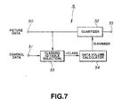
- the quantization circuit 4 is configured as shown in Fig.7, in which the above-mentioned picture data is transmitted via an input terminal 30 to a quantizer 32, while the above-mentioned control data is supplied via an input terminal 31 to a classing circuit 33.
- the classing circuit 33 selects, based upon the above-mentioned control data, a quantization table for quantizing the Y-data, R-Y data and the B-Y data, from among first to fourth quantization tables (Q-tables), having the quantization steps which become progressively rougher, and routes a corresponding selection data to a data quantity calculator 34. If fed with the control data indicating that the block is the red-hued DCT block, the classing circuit selects that quantization table having a quantization step finer by one stage for the DCT block of the R-Y data, and routes the corresponding selection data to the data quantity calculator 34.
- the data quantity calculator 34 calculates an optimum one of quantization numbers in the quantization tables as indicated by the above-mentioned selection data, and routes the quantization coefficients to the quantizer 32. If the block is found to be the red-hued DCT block, the data quantity calculator 34 calculates one of quantization numbers of the quantization tables of the finer stage which is optimum for finer re-quantization of the R-Y data.
- the calculator 34 also calculates such quantization coefficient which, by quantizing the Y data and the B-Y data more roughly substantially in inverse proportion to the refined quantization step for the R-Y data, will give a fixed data length of the one-unit picture data outputted from the variable length coding circuit 5. These quantization coefficients are routed to the quantizer 32.
- the quantizer 32 re-quantizes the Y-data, R-Y data and the B-Y data, based upon the quantization coefficients for respective data supplied from the data quantity calculator 34, for compressing picture data.
- the compressed data is supplied via an output terminal 35 to the variable length encoding circuit 5. shown in Fig.1.
- the quantizer 32 causes the R-Y data to be quantized at a finer quantization step. This is effective in improving reproducibility of the R-Y data in the reproduced picture and alleviating block distortion thereby improving the quality of the reproduced picture.
- the variable length encoding circuit 5 fixes the data quantity of the component data generated from the Y-data, R-Y data and the B-Y data so that the data length per unit will be constant, and routes the resulting fixed length data via an output terminal 9 to an error correction coding combining circuit 25, shown in Fig.3.
- the error correction coding combining circuit 25 combines the component data having the fixed length on the unit basis with audio data from the audio recording processing circuit 22 to generate recording data.
- To these recording data is appended parity data for error correction and the resulting data is supplied to a recording modulating circuit 26.
- the recording modulating circuit 26 modulates the picture data generated by the combining operation in a pre-set manner and routes the modulated picture data to the recording head 27. This results in bias recording of the picture data on the video tape by the recording head 27.
- the picture compression device embodying the present invention may be configured as shown for example in Fig.8.
- the picture compression device shown in Fig.8 is improved over the picture compressing device shown in Fig.1 and comprises a shuffling circuit 52 for shuffling macro-block based picture data generated by the blocking circuit 51, a DCT circuit 53 fed with shuffled data from the shuffling circuit 52, a motion detector 54 and a red detector 55.
- the blocking circuit 51 processes the input picture data by generating DCT blocks, each consisting of 64 pixels arranged in a matrix of 8 vertically arrayed pixels by 8 horizontally arrayed pixels, from the luminance data Y, R-Y data P R and B-Y data P B in the same picture location.
- DCT blocks each consisting of 64 pixels arranged in a matrix of 8 vertically arrayed pixels by 8 horizontally arrayed pixels, from the luminance data Y, R-Y data P R and B-Y data P B in the same picture location.
- the shuffling circuit 52 shuffles the picture data supplied from the blocking circuit 51 on the macro-block basis in a pre-set manner and outputs five shuffled macro-blocks as a lump (unit).
- the DCT circuit 53 processes picture data devoid of motion with discrete cosine transform (DCT), with the 8x8 pixel DCT block as a processing unit, based upon the results of detection by the motion detection unit 54, while processing the moving picture data with discrete cosine transform of sum data or difference data between fields, with the 2 ⁇ 8 ⁇ 4 pixel DCT block as a processing unit, based upon the results of detection by the motion detection unit 54.
- DCT discrete cosine transform
- the picture compression device also comprises a classing circuit 56 fed with a detection output of the red detector 55, an activity detector 57 fed with an output of the DCT circuit 53, a data quantity detector 58 and a quantization circuit 59.
- the activity detector 57 detects the maximum value of the AC coefficient of the DCT transform coefficients of picture data, supplied as an output of the DCT circuit 53 as the information indicating the picture activity, and transmits the classing information data 0 to 3 to the data quantity detector 58, responsive to the maximum value, as shown for example in Fig.3.
- the classing circuit 56 transmits, based upon the classing information data 0 to 3 from the activity detector 57 and a detection output of the red detector 55, the classing information data 0 to 3 shown in Fig.10 to the data quantity detector 58.
- the classing circuit 56 is responsive to the classing information data 0 to 3 from the activity detector 57 to supply to the data quantity detector 58 the first to fourth classing information data 0 to 3 having the progressively rough degree of quantization for the luminance data Y, R-Y data P R and B-Y data P B . Besides, the classing circuit 56 transmits to the data quantity detector 58 the classing information 0 designating the finest quantization for quantizing the DCT block of the R-Y data P R of the red-hued DCT block designated by the detection output of the red detector 55.
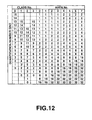
- the data quantity detector 58 calculates, based upon the classing information data 0 to 3 supplied from the classing circuit 56, the optimum quantization coefficient for each of the luminance data Y, R-Y data P R and B-Y data P B from among the quantization coefficients (Q-Nos) in the quantization tables, in order for fixed length picture data to be supplied on the unit basis from the variable length coding circuit 60 fed with an output of the quantization circuit 59. These quantization coefficients are supplied to the quantization circuit 59.
- the 8 ⁇ 8 pixel DCT block for the picture data devoid of the motion, DCTed by the DCT circuit 53, and the 2 ⁇ 8 ⁇ 4 pixel DCT block for the moving picture data, similarly DCTed by the DCT circuit 53, are each divided into eight areas indicated by area numbers 0 to 7 in terms of the AC coefficients.
- the data quantity detector 58 designates the quantization coefficients (Q-Nos) 0 to 15 for each of the classing information data 0 to 3 and specifies weights 1 to 32 for the eight areas, as shown in Fig.12.
- the weights 1 to 32 for the areas indicate the divisors for the input picture data.
- the weight 2 indicates that quantization is to be made with weighting equal to 1/2 for the input picture data.
- the DCT circuit 3 is employed as transform coding means in the above-described embodiments, it may be replaced by other transform coding means, such as an Adamar transform circuit, discrete sine transform circuit, K-L transform circuit or a slant transform circuit.
Landscapes
- Multimedia (AREA)
- Signal Processing (AREA)
- Engineering & Computer Science (AREA)
- General Physics & Mathematics (AREA)
- Physics & Mathematics (AREA)
- Pure & Applied Mathematics (AREA)
- Mathematical Analysis (AREA)
- Mathematical Optimization (AREA)
- Algebra (AREA)
- Discrete Mathematics (AREA)
- Compression Or Coding Systems Of Tv Signals (AREA)
- Color Television Systems (AREA)
- Image Processing (AREA)
- Television Signal Processing For Recording (AREA)
- Closed-Circuit Television Systems (AREA)
- Inspection Of Paper Currency And Valuable Securities (AREA)
Applications Claiming Priority (9)
| Application Number | Priority Date | Filing Date | Title |
|---|---|---|---|
| JP22326693 | 1993-09-08 | ||
| JP22326693 | 1993-09-08 | ||
| JP223266/93 | 1993-09-08 | ||
| JP2811794 | 1994-02-25 | ||
| JP28117/94 | 1994-02-25 | ||
| JP2811794 | 1994-02-25 | ||
| JP161854/94 | 1994-07-14 | ||
| JP16185494A JP3569963B2 (ja) | 1993-09-08 | 1994-07-14 | 画像圧縮装置 |
| JP16185494 | 1994-07-14 |
Publications (3)
| Publication Number | Publication Date |
|---|---|
| EP0648059A2 EP0648059A2 (en) | 1995-04-12 |
| EP0648059A3 EP0648059A3 (enExample) | 1995-05-10 |
| EP0648059B1 true EP0648059B1 (en) | 2000-01-12 |
Family
ID=27286083
Family Applications (1)
| Application Number | Title | Priority Date | Filing Date |
|---|---|---|---|
| EP19940306568 Expired - Lifetime EP0648059B1 (en) | 1993-09-08 | 1994-09-07 | Picture data compression device having color-sensitive quantization |
Country Status (10)
| Country | Link |
|---|---|
| EP (1) | EP0648059B1 (enExample) |
| JP (1) | JP3569963B2 (enExample) |
| KR (1) | KR100338449B1 (enExample) |
| CN (1) | CN1047053C (enExample) |
| AT (1) | ATE188830T1 (enExample) |
| AU (1) | AU686645B2 (enExample) |
| CA (1) | CA2131420C (enExample) |
| DE (1) | DE69422576T2 (enExample) |
| ES (1) | ES2140508T3 (enExample) |
| TW (1) | TW315435B (enExample) |
Families Citing this family (6)
| Publication number | Priority date | Publication date | Assignee | Title |
|---|---|---|---|---|
| WO1998041026A1 (en) | 1997-03-12 | 1998-09-17 | Matsushita Electric Industrial Co., Ltd. | Encoding method, encoder and recording medium, and decoding method, decoder and recording medium |
| WO2003015423A1 (fr) | 2001-08-02 | 2003-02-20 | Sony Corporation | Appareil et procede de traitement d'image et programme de traitement d'image |
| US8487707B2 (en) | 2006-08-08 | 2013-07-16 | Mstar Semiconductor, Inc. | Frequency synthesizer |
| JP4626644B2 (ja) | 2007-11-26 | 2011-02-09 | ソニー株式会社 | 符号化装置、符号化方法、プログラム、及び、撮像装置 |
| EP3550840A1 (en) * | 2012-01-20 | 2019-10-09 | Sony Corporation | Complexity reduction of significance map coding |
| JP7557298B2 (ja) * | 2020-07-17 | 2024-09-27 | 日本放送協会 | 映像符号化装置、映像復号装置及びこれらのプログラム |
Family Cites Families (5)
| Publication number | Priority date | Publication date | Assignee | Title |
|---|---|---|---|---|
| US4816901A (en) * | 1988-04-27 | 1989-03-28 | Universal Video Communications Corp. | Method and system for compressing color video data |
| US5130786A (en) * | 1989-09-12 | 1992-07-14 | Image Data Corporation | Color image compression processing with compensation |
| KR960010392B1 (ko) * | 1990-09-29 | 1996-07-31 | 니뽕 빅터 가부시끼가이샤 | 적응 양자화를 이용한 화상 신호 부호화 복호화 장치 |
| JPH05227441A (ja) * | 1992-02-12 | 1993-09-03 | Mitsubishi Electric Corp | ディジタル画像信号圧縮装置 |
| US5294974A (en) * | 1992-07-24 | 1994-03-15 | Matsushita Electric Corporation Of America | High-definition video encoding system having color-sensitive quantization |
-
1994
- 1994-07-14 JP JP16185494A patent/JP3569963B2/ja not_active Expired - Fee Related
- 1994-09-02 CA CA 2131420 patent/CA2131420C/en not_active Expired - Fee Related
- 1994-09-06 AU AU72852/94A patent/AU686645B2/en not_active Ceased
- 1994-09-07 AT AT94306568T patent/ATE188830T1/de active
- 1994-09-07 ES ES94306568T patent/ES2140508T3/es not_active Expired - Lifetime
- 1994-09-07 EP EP19940306568 patent/EP0648059B1/en not_active Expired - Lifetime
- 1994-09-07 DE DE69422576T patent/DE69422576T2/de not_active Expired - Lifetime
- 1994-09-08 KR KR1019940022571A patent/KR100338449B1/ko not_active Expired - Fee Related
- 1994-09-08 CN CN94113715A patent/CN1047053C/zh not_active Expired - Fee Related
- 1994-09-24 TW TW83108863A patent/TW315435B/zh not_active IP Right Cessation
Non-Patent Citations (1)
| Title |
|---|
| U. TIETZE, CH. SCHENK: "Halbleiter-Schaltungstechnik", 1980, SPRINGER, BERLIN HEIDELBERG NEW YORK 1980 * |
Also Published As
| Publication number | Publication date |
|---|---|
| KR950010641A (ko) | 1995-04-28 |
| KR100338449B1 (ko) | 2002-10-25 |
| EP0648059A2 (en) | 1995-04-12 |
| CA2131420A1 (en) | 1995-03-09 |
| CN1047053C (zh) | 1999-12-01 |
| AU686645B2 (en) | 1998-02-12 |
| DE69422576T2 (de) | 2000-07-06 |
| TW315435B (enExample) | 1997-09-11 |
| ES2140508T3 (es) | 2000-03-01 |
| JPH07288845A (ja) | 1995-10-31 |
| JP3569963B2 (ja) | 2004-09-29 |
| DE69422576D1 (de) | 2000-02-17 |
| CA2131420C (en) | 2005-07-12 |
| EP0648059A3 (enExample) | 1995-05-10 |
| CN1117239A (zh) | 1996-02-21 |
| AU7285294A (en) | 1995-03-23 |
| ATE188830T1 (de) | 2000-01-15 |
Similar Documents
| Publication | Publication Date | Title |
|---|---|---|
| EP0296608B1 (en) | Encoding of a picture signal in consideration of contrast in each picture and decoding corresponding to the encoding | |
| US5724097A (en) | Adaptive quantization of video based on edge detection | |
| JP3245977B2 (ja) | ディジタル画像信号の伝送装置 | |
| EP1006731B1 (en) | Code amount control method and encoding apparatus for carrying it out | |
| USRE37091E1 (en) | Motion compensated prediction interframe coding system | |
| US5369439A (en) | Orthogonal transform encoder using DC component to control quantization step size | |
| EP0559982A2 (en) | Image compression | |
| US6668021B2 (en) | Encoding apparatus | |
| EP0648059B1 (en) | Picture data compression device having color-sensitive quantization | |
| US6674897B1 (en) | Picture data compression device and red data detection device | |
| US5162898A (en) | Color image data compressing apparatus and method | |
| JP3581935B2 (ja) | 高能率符号化装置 | |
| EP0786901B1 (en) | Device for compressing still image data | |
| EP0339938A2 (en) | Method and system for compressing colour video encoded data | |
| JP3218744B2 (ja) | ディジタル画像信号の伝送装置 | |
| KR100436765B1 (ko) | 디지털 비디오 시스템의 신호처리장치 및 방법 | |
| JPH02108372A (ja) | 画像データの圧縮装置、及び画像処理装置 | |
| JP2910416B2 (ja) | 直交変換符号化装置 | |
| JPH07115664A (ja) | 高能率符号化復号化装置 | |
| JPH04367183A (ja) | 画像符号化装置 | |
| JP3144180B2 (ja) | 映像信号処理装置 | |
| JPH1169165A (ja) | 文字画像符号化方法及び装置 | |
| JPH03207190A (ja) | 高能率符号化装置 | |
| JPH06350987A (ja) | ディジタル画像データの量子化装置 | |
| JPH0795092A (ja) | 符号化装置 |
Legal Events
| Date | Code | Title | Description |
|---|---|---|---|
| PUAI | Public reference made under article 153(3) epc to a published international application that has entered the european phase |
Free format text: ORIGINAL CODE: 0009012 |
|
| PUAL | Search report despatched |
Free format text: ORIGINAL CODE: 0009013 |
|
| AK | Designated contracting states |
Kind code of ref document: A2 Designated state(s): AT DE ES FR GB IT NL |
|
| AK | Designated contracting states |
Kind code of ref document: A3 Designated state(s): AT DE ES FR GB IT NL |
|
| 17P | Request for examination filed |
Effective date: 19951004 |
|
| 17Q | First examination report despatched |
Effective date: 19980209 |
|
| GRAG | Despatch of communication of intention to grant |
Free format text: ORIGINAL CODE: EPIDOS AGRA |
|
| GRAG | Despatch of communication of intention to grant |
Free format text: ORIGINAL CODE: EPIDOS AGRA |
|
| GRAG | Despatch of communication of intention to grant |
Free format text: ORIGINAL CODE: EPIDOS AGRA |
|
| GRAH | Despatch of communication of intention to grant a patent |
Free format text: ORIGINAL CODE: EPIDOS IGRA |
|
| GRAH | Despatch of communication of intention to grant a patent |
Free format text: ORIGINAL CODE: EPIDOS IGRA |
|
| GRAA | (expected) grant |
Free format text: ORIGINAL CODE: 0009210 |
|
| AK | Designated contracting states |
Kind code of ref document: B1 Designated state(s): AT DE ES FR GB IT NL |
|
| REF | Corresponds to: |
Ref document number: 188830 Country of ref document: AT Date of ref document: 20000115 Kind code of ref document: T |
|
| REF | Corresponds to: |
Ref document number: 69422576 Country of ref document: DE Date of ref document: 20000217 |
|
| REG | Reference to a national code |
Ref country code: ES Ref legal event code: FG2A Ref document number: 2140508 Country of ref document: ES Kind code of ref document: T3 |
|
| ITF | It: translation for a ep patent filed | ||
| ET | Fr: translation filed | ||
| PLBE | No opposition filed within time limit |
Free format text: ORIGINAL CODE: 0009261 |
|
| STAA | Information on the status of an ep patent application or granted ep patent |
Free format text: STATUS: NO OPPOSITION FILED WITHIN TIME LIMIT |
|
| 26N | No opposition filed | ||
| REG | Reference to a national code |
Ref country code: GB Ref legal event code: IF02 |
|
| PGFP | Annual fee paid to national office [announced via postgrant information from national office to epo] |
Ref country code: IT Payment date: 20100927 Year of fee payment: 17 |
|
| PGFP | Annual fee paid to national office [announced via postgrant information from national office to epo] |
Ref country code: FR Payment date: 20110928 Year of fee payment: 18 Ref country code: DE Payment date: 20110923 Year of fee payment: 18 Ref country code: ES Payment date: 20110916 Year of fee payment: 18 Ref country code: AT Payment date: 20110914 Year of fee payment: 18 Ref country code: GB Payment date: 20110920 Year of fee payment: 18 |
|
| PGFP | Annual fee paid to national office [announced via postgrant information from national office to epo] |
Ref country code: NL Payment date: 20110929 Year of fee payment: 18 |
|
| REG | Reference to a national code |
Ref country code: NL Ref legal event code: V1 Effective date: 20130401 |
|
| REG | Reference to a national code |
Ref country code: AT Ref legal event code: MM01 Ref document number: 188830 Country of ref document: AT Kind code of ref document: T Effective date: 20120907 |
|
| GBPC | Gb: european patent ceased through non-payment of renewal fee |
Effective date: 20120907 |
|
| REG | Reference to a national code |
Ref country code: FR Ref legal event code: ST Effective date: 20130531 |
|
| PG25 | Lapsed in a contracting state [announced via postgrant information from national office to epo] |
Ref country code: GB Free format text: LAPSE BECAUSE OF NON-PAYMENT OF DUE FEES Effective date: 20120907 Ref country code: DE Free format text: LAPSE BECAUSE OF NON-PAYMENT OF DUE FEES Effective date: 20130403 Ref country code: AT Free format text: LAPSE BECAUSE OF NON-PAYMENT OF DUE FEES Effective date: 20120907 |
|
| PG25 | Lapsed in a contracting state [announced via postgrant information from national office to epo] |
Ref country code: FR Free format text: LAPSE BECAUSE OF NON-PAYMENT OF DUE FEES Effective date: 20121001 Ref country code: NL Free format text: LAPSE BECAUSE OF NON-PAYMENT OF DUE FEES Effective date: 20130401 Ref country code: IT Free format text: LAPSE BECAUSE OF NON-PAYMENT OF DUE FEES Effective date: 20120907 |
|
| REG | Reference to a national code |
Ref country code: DE Ref legal event code: R119 Ref document number: 69422576 Country of ref document: DE Effective date: 20130403 |
|
| REG | Reference to a national code |
Ref country code: ES Ref legal event code: FD2A Effective date: 20131018 |
|
| PG25 | Lapsed in a contracting state [announced via postgrant information from national office to epo] |
Ref country code: ES Free format text: LAPSE BECAUSE OF NON-PAYMENT OF DUE FEES Effective date: 20120908 |