EP0645653A2 - Dispositif électrooptique d'émission et de réception combiné pour fibres optiques, notamment pour l'utilisation dans un bus à fibre optique - Google Patents
Dispositif électrooptique d'émission et de réception combiné pour fibres optiques, notamment pour l'utilisation dans un bus à fibre optique Download PDFInfo
- Publication number
- EP0645653A2 EP0645653A2 EP94110917A EP94110917A EP0645653A2 EP 0645653 A2 EP0645653 A2 EP 0645653A2 EP 94110917 A EP94110917 A EP 94110917A EP 94110917 A EP94110917 A EP 94110917A EP 0645653 A2 EP0645653 A2 EP 0645653A2
- Authority
- EP
- European Patent Office
- Prior art keywords
- optical
- transmitting
- bus
- electro
- optical fiber
- Prior art date
- Legal status (The legal status is an assumption and is not a legal conclusion. Google has not performed a legal analysis and makes no representation as to the accuracy of the status listed.)
- Withdrawn
Links
Images
Classifications
-
- G—PHYSICS
- G02—OPTICS
- G02B—OPTICAL ELEMENTS, SYSTEMS OR APPARATUS
- G02B6/00—Light guides; Structural details of arrangements comprising light guides and other optical elements, e.g. couplings
- G02B6/24—Coupling light guides
- G02B6/42—Coupling light guides with opto-electronic elements
- G02B6/4201—Packages, e.g. shape, construction, internal or external details
- G02B6/4246—Bidirectionally operating package structures
Definitions
- the invention relates to an electro / optical combined transmitting and receiving device for optical fibers, in particular for use in an optical fiber bus.
- Such a device is known from the article by M. Agethen and N. Backpack, Electronics 18/1992, pages 56 to 60. It is a standardized optical duplex connector available on the market, in which two electro / optical converters are integrated in a connector at a relatively large distance from one another and are each connected to an optical fiber core, the two wires being one common insulating sleeve are surrounded.
- an optical serial multimaster bus system with an implementable standard bus protocol which is explained in more detail below with reference to FIGS. 2 to 4, is also known, in which the bus participants each use one of the known combined transmitting and receiving devices, each via two optical fibers with a passive optical star coupler and thereby connected to each other. Accordingly, the components of an optical fiber bus system with arbitration are known, but only in a two-wire version.
- the invention has for its object to provide a new, less expensive electro / optical combined transmitting and receiving device for optical fibers, the is particularly, but not only, suitable for simplifying an optical waveguide bus system.
- This object is achieved with a transmitting and receiving device of the type mentioned at the outset according to the invention in that a transmitting and a receiving element are arranged so closely adjacent that they have access to the same optical fiber interface.
- the combined transmitting and receiving device advantageously enables coupling to a single-conductor optical waveguide connection in suitable cases in which no permanent forward and reverse connection is required.
- This can advantageously be used to simplify, in particular, optical bus systems in which the subscribers are usually connected to the bus by a two-conductor optical fiber connection.
- An optical serial multimaster bus system with at least two transmitting and receiving devices according to the invention is particularly advantageous, in which the bus subscribers are each electrically connected to one of the combined transmitting and receiving devices, and by means of these in each case via only one optical waveguide with a passive optical star coupler and are connected to each other.
- This concept according to the invention reduces the number of optical fiber coupling plugs by half, as does the number and thus also the length of the optical fiber itself.
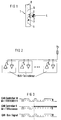
- FIG. 1 in FIG. 1 denotes a transmit and receive (S / E) module.
- a luminescent diode 2 as the transmitting element and a photodiode 3 as the receiving element are arranged close to one another on a substrate carrier 5, in particular a stamped metal system carrier.
- the two diodes 2 and 3 are so closely adjacent that they have access to one and the same optical fiber interface 4.
- all suitable electro / optical converters can be used as transmitting and receiving elements, although a luminescent diode is considerably more advantageous for the transmitting element than a laser diode, since otherwise the laser light radiation on the other transmitting diodes can cause interference.
- FIG. 1 shows an integrated circuit 6 and a discrete component, for example a capacitor 7, which are electrically connected to the transmitting and receiving elements 2 and 3 and together form an evaluation circuit with them.
- the entire arrangement is provided with a housing 8 and forms an S / E module 1, in which the optical fiber interface 4 is also integrated.
- bus In order to save physical connection lines or to be able to use the available channels optimally, it is known to implement a communication network in the form of a "bus", the multiple use of a single transmission medium for all network participants, for example twisted electrical two-wire lines, or a two-wire optical waveguide , is the focus of time-division multiplexing.
- Serial fieldbus concepts so-called buses, for example CAN, ABUS, VAN, J1850, are increasingly being developed to limit the cable harnesses that grow with the increasing proportion of electronics in motor vehicles. These buses are used to network control units, actuators and sensors within an automobile, or in general in industrial control systems.
- the various multimaster bus concepts are essentially the same in their bus access procedure.
- the multiple use of the transmission medium requires an agreement on the communication organization, i.e. who is allowed to use the transmission medium at what time.
- this agreement the bus protocol, means that only one bus participant speaks and all others listen.
- the participant (master) who wants to speak first checks whether no other participant wants to speak. When another participant speaks, he waits to speak and listen.
- the case of conflict when two participants start speaking at the same time is settled by an arbitration system. This is based in a manner known per se on the distinguishability of dominant and recessive bit signals, which are initially based on the in Figure 2 illustrated conventional non-optical bus is explained.
- FIG. 2 shows a bus line on which a potential Vs is present.
- a number of bus subscribers are each electrically connected to the bus line via two connections, so that the subscribers can give digital electrical signals to the bus line via the transistors shown, or can receive such signals applied to the bus line.
- Each bus subscriber can pull the bus line to "low” by applying a "one" bit signal to the base of the respective transistor shown in FIG. 2 and causing a voltage drop on the bus line via the conductive collector. If a participant has generated a "low” voltage state on the bus, corresponding to a "zero” bit signal, no other participant can bring the bus to "high”. The "Low" voltage signals on the bus side are therefore dominant over the "High” voltage signals on the bus side.
- FIG. 3 the function of the arbitration system based on the dominance of the "zero signal" on the bus side compared to the recessive "one" signal is shown using the example of the bus protocol CAN, which is frequently used in industry.
- the start bit S is followed by an 11-bit identifier, which is transmitted with each message. Every message that is sent can be received by all participants at the same time. In the event of a conflict, i.e. when several participants start to send at the same time, the participant who sends the message with the highest priority identifier prevails.
- the process is such that all participants with an active send job start sending the identifier after synchronization.
- each participant checks whether the bit sent and read match. If a subscriber recognizes that the bus level is dominant even though it has sent a recessive signal, it stops sending and becomes the receiver. In the example shown in FIG. 3, the subscriber N already notices when the fourth bit is transmitted that his information sent does not match the information received. Participant N has lost arbitration and is becoming a listener. In general, only one participant remains active as a transmitter after sending out the complete identifier.
- the arbitration system described above works in exactly the same way if "light on” is set equal to a "low signal” and the optical transmitter / receiver are connected to one another via a star coupler.
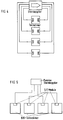
- a star coupler Such an optical bus system with a star structure, already known from the article by M. Agethen et al, is shown in FIG.
- a known passive star coupler is the safest and cheapest solution for networks with small distances.
- the known optical two-wire bus system shown in FIG. 4 is complex.
- FIG. 5 shows an optical bus system according to the invention, in which the bus users are each electrically connected to one of the combined transmitting and receiving devices, and by means of this in each case via only one optical waveguide with a passive optical star coupler, in particular a reflection coupler, and thereby with one another are connected.
- the transmitter / receiver modules with a combined transmitter and receiver as well as the fiber optic interfaces are connected in a star and with very little loss.
- a standard bus protocol, such as CAN can be implemented for arbitration, the state "light on” being of course actually dominant over "light off”.
- the receiver sees light from its own transmitter and also from the bus line. If the own transmitter transmitter does not emit light, i.e. a recessive signal, but a light signal arrives from the bus line, the respective subscriber becomes the transmitter to the receiver.
- the concept according to the invention also offers the possibility of using simplified star couplers in its construction.
- the bus according to the invention is faster due to the faster response times in arbitrage. With the reduced number of interfaces, the attenuation in the transmission system is also lower, which brings about an advantageous increase in the distance which can be bridged, in particular for plastic optical fibers.
- the transmitter / receiver module according to the invention alone or when used in the bus system described, is overall less complex and more reliable than previously known solutions.
- Complex networks can be set up by connecting a plurality of passive bus systems according to the invention by means of an active optical star coupler. With the help of an active coupling, hybrid solutions of optical and electrical networks according to the invention are also possible.
Landscapes
- Physics & Mathematics (AREA)
- General Physics & Mathematics (AREA)
- Optics & Photonics (AREA)
- Optical Couplings Of Light Guides (AREA)
- Optical Communication System (AREA)
Applications Claiming Priority (2)
| Application Number | Priority Date | Filing Date | Title |
|---|---|---|---|
| DE4328970 | 1993-08-27 | ||
| DE4328970 | 1993-08-27 |
Publications (2)
| Publication Number | Publication Date |
|---|---|
| EP0645653A2 true EP0645653A2 (fr) | 1995-03-29 |
| EP0645653A3 EP0645653A3 (fr) | 1996-02-07 |
Family
ID=6496242
Family Applications (1)
| Application Number | Title | Priority Date | Filing Date |
|---|---|---|---|
| EP94110917A Withdrawn EP0645653A3 (fr) | 1993-08-27 | 1994-07-13 | Dispositif électrooptique d'émission et de réception combiné pour fibres optiques, notamment pour l'utilisation dans un bus à fibre optique. |
Country Status (1)
| Country | Link |
|---|---|
| EP (1) | EP0645653A3 (fr) |
Cited By (1)
| Publication number | Priority date | Publication date | Assignee | Title |
|---|---|---|---|---|
| DE102004027614A1 (de) * | 2004-06-05 | 2005-12-22 | Conti Temic Microelectronic Gmbh | Aufprall-Sensoranordnung in einem Fahrzeug |
Family Cites Families (7)
| Publication number | Priority date | Publication date | Assignee | Title |
|---|---|---|---|---|
| GB1461693A (en) * | 1974-01-15 | 1977-01-19 | Marconi Co Ltd | Fibre optic couplers |
| GB2011610A (en) * | 1977-12-23 | 1979-07-11 | Elliot Bros Ltd | Fibre optic terminal |
| DE3601729A1 (de) * | 1986-01-22 | 1987-07-23 | Licentia Gmbh | Faseroptische koppelanordnung |
| US5073982A (en) * | 1989-09-01 | 1991-12-17 | General Electric Company | Apparatus for connecting multiple passive stars in a fiber optic network |
| JP2631902B2 (ja) * | 1990-04-20 | 1997-07-16 | 日本航空電子工業 株式会社 | 光集積回路 |
| JPH0748946B2 (ja) * | 1990-06-29 | 1995-05-24 | 三洋電機株式会社 | スイッチング電源装置 |
| FR2682240A1 (fr) * | 1991-10-04 | 1993-04-09 | Cit Alcatel | Systeme de raccordement optique de terminaux d'abonnes a un centre local d'un reseau de telecommunications. |
-
1994
- 1994-07-13 EP EP94110917A patent/EP0645653A3/fr not_active Withdrawn
Cited By (1)
| Publication number | Priority date | Publication date | Assignee | Title |
|---|---|---|---|---|
| DE102004027614A1 (de) * | 2004-06-05 | 2005-12-22 | Conti Temic Microelectronic Gmbh | Aufprall-Sensoranordnung in einem Fahrzeug |
Also Published As
| Publication number | Publication date |
|---|---|
| EP0645653A3 (fr) | 1996-02-07 |
Similar Documents
| Publication | Publication Date | Title |
|---|---|---|
| DE3851945T2 (de) | Optische Rückwandverdrahtung. | |
| EP0033445B1 (fr) | Système passif à barre omnibus pour des systèmes décentralisés de multiprocesseur, en particulier pour des systèmes de multimicroordinateur | |
| DE69831891T2 (de) | Optischer Rechnerbus mit dynamischer Bandbreitenzuordnung | |
| DE102008030222B4 (de) | Steuergerät und Verfahren zum Betrieb des Steuergeräts sowie KFZ mit derartigem Steuergerät | |
| DE19850125B4 (de) | Netzteil für Spannungsversorgung eines Busses | |
| DE112010003769T5 (de) | Fahrzeugkommunikationssystem, optischer kommunikationskabelbaum und optische teilungsvorrichtung | |
| DE19709174B4 (de) | Optisches Bussystem | |
| DE60010327T2 (de) | Verfahren und vorrichtung zum senden und empfangen von stromversorgung und daten mittels zeitmultiplexübertragung | |
| DE19624528B4 (de) | Verfahren zur Steuerung von Informationsübertragung zwischen Komponenten und Komponente zur Durchführung des Verfahrens | |
| WO2019122064A1 (fr) | Module de batterie électrique utilisant une communication optique | |
| DE10133749B4 (de) | Netzwerkkomponente für ein optisches Netzwerk mit Notlauffunktion, insbesondere für ein optisches Netzwerk in Ringtopologie | |
| DE102011100212A1 (de) | Sende-Empfangsvorrichtung und Verfahren zum Senden und Empfangen von Daten | |
| DE4106726B4 (de) | Kommunikationsnetzwerk in Kraftfahrzeugen | |
| EP0645653A2 (fr) | Dispositif électrooptique d'émission et de réception combiné pour fibres optiques, notamment pour l'utilisation dans un bus à fibre optique | |
| DE10335036A1 (de) | Modulares System | |
| WO1991007031A1 (fr) | Bus controleur pour un multiplexeur de signaux numeriques souple et programmable | |
| DE19606940B4 (de) | Asynchrones Bussystem mit gemeinsamer Informations- und Energieübertragung auf der Basis einer maximal zweiadrigen Leitung | |
| EP0183998A2 (fr) | Reconnaissance de collisions d'informations | |
| DE102004032839B3 (de) | ASI-System zum Anschluß mehrerer Sensoren und/oder Aktuatoren an eine Steuerung | |
| EP0162994A1 (fr) | Réseau de communication et son utilisation | |
| DE69500281T2 (de) | Kompatibelschnittstelle für die Steueranlage von Geräten im Haus, in der Industrie oder in der beruflichen Umgebung | |
| EP0127570A2 (fr) | Système de communication locale à réseau en étoile et à canaux optiques | |
| DE3622824C2 (fr) | ||
| EP3841688B1 (fr) | Convertisseur de média et procédé de fonctionnement d'un convertisseur de média | |
| EP1191731B1 (fr) | Procédé et dispositif de transmission de données résistant aux perturbations sur un bus |
Legal Events
| Date | Code | Title | Description |
|---|---|---|---|
| PUAI | Public reference made under article 153(3) epc to a published international application that has entered the european phase |
Free format text: ORIGINAL CODE: 0009012 |
|
| AK | Designated contracting states |
Kind code of ref document: A2 Designated state(s): BE DE ES FR GB IT SE |
|
| PUAL | Search report despatched |
Free format text: ORIGINAL CODE: 0009013 |
|
| AK | Designated contracting states |
Kind code of ref document: A3 Designated state(s): BE DE ES FR GB IT SE |
|
| 17P | Request for examination filed |
Effective date: 19960806 |
|
| RAP1 | Party data changed (applicant data changed or rights of an application transferred) |
Owner name: TYCO ELECTRONICS LOGISTICS AG |
|
| 17Q | First examination report despatched |
Effective date: 20000303 |
|
| STAA | Information on the status of an ep patent application or granted ep patent |
Free format text: STATUS: THE APPLICATION IS DEEMED TO BE WITHDRAWN |
|
| 18D | Application deemed to be withdrawn |
Effective date: 20000714 |