EP0645548B1 - Kupplungsvorrichtung - Google Patents
Kupplungsvorrichtung Download PDFInfo
- Publication number
- EP0645548B1 EP0645548B1 EP94113874A EP94113874A EP0645548B1 EP 0645548 B1 EP0645548 B1 EP 0645548B1 EP 94113874 A EP94113874 A EP 94113874A EP 94113874 A EP94113874 A EP 94113874A EP 0645548 B1 EP0645548 B1 EP 0645548B1
- Authority
- EP
- European Patent Office
- Prior art keywords
- sleeve
- spring
- bush
- closure part
- component
- Prior art date
- Legal status (The legal status is an assumption and is not a legal conclusion. Google has not performed a legal analysis and makes no representation as to the accuracy of the status listed.)
- Expired - Lifetime
Links
- 230000008878 coupling Effects 0.000 title 1
- 238000010168 coupling process Methods 0.000 title 1
- 238000005859 coupling reaction Methods 0.000 title 1
- 230000004323 axial length Effects 0.000 claims description 4
- 230000000284 resting effect Effects 0.000 claims 1
- 238000005553 drilling Methods 0.000 description 4
- 230000007704 transition Effects 0.000 description 2
- 241000209035 Ilex Species 0.000 description 1
- 230000005540 biological transmission Effects 0.000 description 1
- 210000003746 feather Anatomy 0.000 description 1
Images


Classifications
-
- F—MECHANICAL ENGINEERING; LIGHTING; HEATING; WEAPONS; BLASTING
- F16—ENGINEERING ELEMENTS AND UNITS; GENERAL MEASURES FOR PRODUCING AND MAINTAINING EFFECTIVE FUNCTIONING OF MACHINES OR INSTALLATIONS; THERMAL INSULATION IN GENERAL
- F16D—COUPLINGS FOR TRANSMITTING ROTATION; CLUTCHES; BRAKES
- F16D1/00—Couplings for rigidly connecting two coaxial shafts or other movable machine elements
- F16D1/10—Quick-acting couplings in which the parts are connected by simply bringing them together axially
- F16D1/108—Quick-acting couplings in which the parts are connected by simply bringing them together axially having retaining means rotating with the coupling and acting by interengaging parts, i.e. positive coupling
- F16D1/116—Quick-acting couplings in which the parts are connected by simply bringing them together axially having retaining means rotating with the coupling and acting by interengaging parts, i.e. positive coupling the interengaging parts including a continuous or interrupted circumferential groove in the surface of one of the coupling parts
-
- F—MECHANICAL ENGINEERING; LIGHTING; HEATING; WEAPONS; BLASTING
- F16—ENGINEERING ELEMENTS AND UNITS; GENERAL MEASURES FOR PRODUCING AND MAINTAINING EFFECTIVE FUNCTIONING OF MACHINES OR INSTALLATIONS; THERMAL INSULATION IN GENERAL
- F16D—COUPLINGS FOR TRANSMITTING ROTATION; CLUTCHES; BRAKES
- F16D3/00—Yielding couplings, i.e. with means permitting movement between the connected parts during the drive
- F16D3/16—Universal joints in which flexibility is produced by means of pivots or sliding or rolling connecting parts
- F16D3/26—Hooke's joints or other joints with an equivalent intermediate member to which each coupling part is pivotally or slidably connected
- F16D3/38—Hooke's joints or other joints with an equivalent intermediate member to which each coupling part is pivotally or slidably connected with a single intermediate member with trunnions or bearings arranged on two axes perpendicular to one another
- F16D3/382—Hooke's joints or other joints with an equivalent intermediate member to which each coupling part is pivotally or slidably connected with a single intermediate member with trunnions or bearings arranged on two axes perpendicular to one another constructional details of other than the intermediate member
- F16D3/387—Fork construction; Mounting of fork on shaft; Adapting shaft for mounting of fork
-
- F—MECHANICAL ENGINEERING; LIGHTING; HEATING; WEAPONS; BLASTING
- F16—ENGINEERING ELEMENTS AND UNITS; GENERAL MEASURES FOR PRODUCING AND MAINTAINING EFFECTIVE FUNCTIONING OF MACHINES OR INSTALLATIONS; THERMAL INSULATION IN GENERAL
- F16B—DEVICES FOR FASTENING OR SECURING CONSTRUCTIONAL ELEMENTS OR MACHINE PARTS TOGETHER, e.g. NAILS, BOLTS, CIRCLIPS, CLAMPS, CLIPS OR WEDGES; JOINTS OR JOINTING
- F16B2200/00—Constructional details of connections not covered for in other groups of this subclass
- F16B2200/69—Redundant disconnection blocking means
-
- F—MECHANICAL ENGINEERING; LIGHTING; HEATING; WEAPONS; BLASTING
- F16—ENGINEERING ELEMENTS AND UNITS; GENERAL MEASURES FOR PRODUCING AND MAINTAINING EFFECTIVE FUNCTIONING OF MACHINES OR INSTALLATIONS; THERMAL INSULATION IN GENERAL
- F16D—COUPLINGS FOR TRANSMITTING ROTATION; CLUTCHES; BRAKES
- F16D1/00—Couplings for rigidly connecting two coaxial shafts or other movable machine elements
- F16D1/10—Quick-acting couplings in which the parts are connected by simply bringing them together axially
- F16D2001/103—Quick-acting couplings in which the parts are connected by simply bringing them together axially the torque is transmitted via splined connections
-
- Y—GENERAL TAGGING OF NEW TECHNOLOGICAL DEVELOPMENTS; GENERAL TAGGING OF CROSS-SECTIONAL TECHNOLOGIES SPANNING OVER SEVERAL SECTIONS OF THE IPC; TECHNICAL SUBJECTS COVERED BY FORMER USPC CROSS-REFERENCE ART COLLECTIONS [XRACs] AND DIGESTS
- Y10—TECHNICAL SUBJECTS COVERED BY FORMER USPC
- Y10T—TECHNICAL SUBJECTS COVERED BY FORMER US CLASSIFICATION
- Y10T403/00—Joints and connections
- Y10T403/59—Manually releaseable latch type
- Y10T403/599—Spring biased manipulator
-
- Y—GENERAL TAGGING OF NEW TECHNOLOGICAL DEVELOPMENTS; GENERAL TAGGING OF CROSS-SECTIONAL TECHNOLOGIES SPANNING OVER SEVERAL SECTIONS OF THE IPC; TECHNICAL SUBJECTS COVERED BY FORMER USPC CROSS-REFERENCE ART COLLECTIONS [XRACs] AND DIGESTS
- Y10—TECHNICAL SUBJECTS COVERED BY FORMER USPC
- Y10T—TECHNICAL SUBJECTS COVERED BY FORMER US CLASSIFICATION
- Y10T403/00—Joints and connections
- Y10T403/70—Interfitted members
- Y10T403/7026—Longitudinally splined or fluted rod
- Y10T403/7028—Splayed or having a cam surface for anti-backlash
Definitions
- the invention relates to a device for connecting a serrated shaft, which is used for the transmission of torque, with a component carrying an internally serrated sleeve, according to the preamble of claim 1.
- a device for connecting a serrated shaft which is used for the transmission of torque, with a component carrying an internally serrated sleeve, according to the preamble of claim 1.
- Such a device is e.g. known from document EP-A-92 669.
- the object of the invention is to provide a connection for the components mentioned, which can be produced without tools and without tools and can also be released again, and with which torques can be transmitted without play. Requirements of this type are placed on steering columns of motor vehicles, but the invention is not restricted to this special field of application.
- the invention provides those measures that are the content and subject of the characterizing part of claim 1. Expedient embodiments of the invention are set out in the subclaims.
- a shaft journal 1 which for example forms a steering shaft of a motor vehicle steering system, has serration 2 at one end and a circumferential groove 4 with an arcuate cross section near its end face 3.
- This shaft journal 1 is now to be connected to a universal joint, of which an articulated fork 5 is shown in FIG. 1.
- This joint fork 5 is fixedly connected in a suitable manner to a sleeve 6, which is shown in longitudinal section in FIG. 4.
- This sleeve 6 has a first section 7 with an internal serration 8, the outer boundary surface 9 of this section 7 having a conical suit diverging against the receiving side of the sleeve 6, for example of approximately two degrees of arc.
- a plurality of axially parallel longitudinal slots 10 subdivide this section 7 of the sleeve 6 in the circumferential direction thereof into individual resilient tabs 11.
- the axial length of this serration 8 is at least as large as that of the shaft journal 1.
- This first section 7 of the sleeve 6 is adjoined by a second section 12 of cylindrical shape which has a plurality of bores 13 in the circumferential direction in a cross-sectional plane which is close to the first section 7.
- This section 12 is firmly connected to the joint fork 5.
- This section 12 is somewhat longer than the section 7 discussed first.
- a pot-like closure part 14 which is held by the force of a spring 15 on an inner shoulder 16 in the transition from one section 7 to the other section 12 of the sleeve 6, wherein the axial length of this pot-like closure part 14 is approximately as large as the diameter of the bores 13.
- the spring 15 lying within the sleeve 6 with a small spring constant is supported with its other end on a disk-shaped abutment 17, which, for example, by means of a press fit on the Sleeve 6 can be fixed.
- This sleeve 6 with the disk-shaped abutment 17 could also be formed in one piece as a turned part.
- the first section 7, which carries the inner serration 8, is shorter than the second section 12 of the sleeve 6, and the outer lateral surface 27 of this second section 12 transitions to the first section 7 via a step 28 or a shoulder.
- This sleeve 6 is now received by a bush 18 which is axially displaceable relative to it.
- This bushing 18 has a bore 19 corresponding to the conical tightening of the bushing 6, to which a circumferential groove 20 connects in the axial direction of the bushing 18 and in which a number of locking balls 21 corresponding to the number of the bore 13 are located.
- the diameter of the locking balls 21 corresponds to the diameter of the bores 13.
- this bushing 18 receives with its lower end-side bore 22 a helical spring 23, which bears at one end on the joint fork 5 and at the other end on an inner shoulder 24 , with which the bore 22 merges into a subsequent bore 25 with a tapered cross section.
- This coil spring 23 is penetrated by the sleeve 6, its spring constant is many times greater than that of the spring 15 lying in the sleeve 6, which cooperates with the closure part 14.
- the diameter of the bores 13 lying in a cross-sectional plane of the second section 12 of the sleeve 6 is as large as the diameter of the locking balls 21, and the depth of the holes 3 is preferably provided close to the end face 3 of the shaft journal 1 Groove 4 is smaller than half the diameter of the locking balls 21.
- the width of the annular space which is limited on the one hand by the bottom of the groove 20 screwed into the bushing 18 and on the other hand by the locking part 14 in its closed position, corresponds at least to the diameter of the locking balls 21. Due to the pot-like design of the closure part 14, one end of the spring 15 carrying it is guided and held.
- the spring 23 with the large spring constant lies in an annular gap which is delimited by the second section 12 of the sleeve 6 with the wall of the bore 22 of the bushing 18 receiving it.
- the axial length of this annular space corresponds approximately to the length of the compressed, operationally pretensioned spring 23.
- the length of the sleeve 6 is greater than the length of the bushing 18.
- the groove provided on the inside of the bushing 18 and used to receive the locking balls 21 is approximately in arranged middle longitudinal region of the bushing 18.
- Fig. 1 now shows the parts to be connected in alignment with each other, but still separated from each other.
- the inner spring 15 presses the pot-like closure part 14 against the shoulder 16, whereby the locking balls 21 are initially prevented from entering the sleeve 6 through the bores 13.
- the outer spring 23 is preloaded, the upper part of the sleeve 6 or its section 7 partially projects beyond the end face 26 of the bushing 18.
- the initially preloaded spring 23 comes into action, which now pushes the bushing 18 upwards with great force, as a result of which the locking balls 21 which have fallen into the bore 13 are held in their locked position on the one hand and the tabs 11 of section 7 formed by the longitudinal slots 10 on the other hand the sleeve 6 are radially compressed so that the two serrations 2 and 8 are connected to each other without play.
- This sufficiently takes into account the requirement for a play-free connection in the direction of rotation of the shaft or shaft parts, as are necessary for steering systems for motor vehicles.
Description
- Die Erfindung bezieht sich auf eine Vorrichtung zum Verbinden eines kerbverzahnten, der Übertragung von Drehmomenten dienenden Wellenzapfens mit einem eine innen kerbverzahnte Hülse tragenden Bauteil gemäß dem Oberbegriff von Anspruch 1. Eine solche Vorrichtung ist z.B. aus Dokument EP-A-92 669 bekannt.
- Aufgabe der Erfindung ist es, eine Verbindung für die erwähnten Bauteile zu schaffen, die ohne Hilfsmittel und ohne Werkzeuge hergestellt und auch wieder gelöst werden kann, und mit welcher Drehmomente spielfrei übertragen werden können. Forderungen dieser Art werden an Lenksäulen von Kraftfahrzeugen gestellt, doch ist die Erfindung auf dieses spezielle Anwendungsgebiet nicht beschränkt.
- Zur Lösung dieser komplexen Aufgabe sieht die Erfindung jene Maßnahmen vor, die Inhalt und Gegenstand des kennzeichnenden Teiles des Patentanspruches 1 sind. Zweckmäßige Ausgestaltungen der Erfindung sind in den Unteransprüchen festgehalten.
- Die Erfindung wird nachstehend anhand eines Ausführungsbeispieles näher beschrieben. Es zeigen:
- Fig. 1 nach Art einer Explosionszeichnung die vorerst getrennten, zu verbindenden Bauteile, wobei der eine Bauteil im Längsschnitt dargestellt ist;
- Fig. 2 einen Montageschritt während der Herstellung der Verbindung;
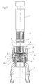
- Fig. 3 die fertiggestellte Verbindung;
- Fig. 4 die Hülse im Längsschnitt.
- Ein Wellenzapfen 1, der beispielsweise eine Lenkwelle einer Kraftfahrzeuglenkung bildet, besitzt an seinem einen Ende eine Kerbverzahnung 2 und nahe seiner Stirnseite 3 eine umlaufende Nut 4 mit einem kreisbogenförmigen Querschnitt.
- Dieser Wellenzapfen 1 ist nun mit einem Kardangelenk zu verbinden, von dem in Fig. 1 die eine Gelenkgabel 5 gezeigt ist. Diese Gelenkgabel 5 ist in einer geeigneten Weise mit einer Hülse 6 fest verbunden, die in Fig. 4 im Längsschnitt gezeigt ist. Diese Hülse 6 besitzt einen ersten Abschnitt 7 mit einer inneren Kerbverzahnung 8, wobei die äußere Begrenzungsfläche 9 dieses Abschnittes 7 einen gegen die Aufnahmeseite der Hülse 6 divergierenden konischen Anzug besitzt, beispielsweise von annähernd zwei Bogengraden. Mehrere achsparallele Längsschlitze 10 unterteilen diesen Abschnitt 7 der Hülse 6 in Umfangsrichtung derselben in einzelne federnde Laschen 11. Die achsiale Länge dieser Kerbverzahnung 8 ist mindestens so groß wie jene des Wellenzapfens 1.
- An diesen ersten Abschnitt 7 der Hülse 6 schließt ein zweiter Abschnitt 12 an von zylindrischer Gestalt, der in einer Querschnittsebene, die nahe dem ersten Abschnitt 7 liegt, in Umfangsrichtung mehrere Bohrungen 13 aufweist. Dieser Abschnitt 12 ist mit der Gelenkgabel 5 fest verbunden. Dieser Abschnitt 12 ist etwas länger als der erstbesprochene Abschnitt 7. Innerhalb dieses Abschnittes 12 liegt ein topfartiger Verschlußteil 14, der durch die Kraft einer Feder 15 an einer inneren Schulter 16 im Übergang vom einen Abschnitt 7 zum anderen Abschnitt 12 der Hülse 6 gehalten ist, wobei die achsiale Länge dieses topfartigen Verschlußteiles 14 etwa so groß ist wie der Durchmesser der Bohrungen 13. Die innerhalb der Hülse 6 liegende Feder 15 mit kleiner Federkonstante stützt sich mit ihrem anderen Ende an einem scheibenförmigen Widerlager 17 ab, das beispielsweise mittels eines Preßsitzes an der Hülse 6 festgelegt sein kann. Diese Hülse 6 mit dem scheibenförmigen Widerlager 17 könnte auch einstückig als Drehteil ausgebildet sein. Der erste, die innere Kerbverzahnung 8 tragende Abschnitt 7 ist kürzer als der zweite Abschnitt 12 der Hülse 6, und die äußere Mantelfläche 27 dieses zweiten Abschnittes 12 geht über eine Stufe 28 bzw. einen Absatz zum ersten Abschnitt 7 über.
- Diese Hülse 6 ist nun von einer Buchse 18 aufgenommen, die relativ zu ihr achsial verschiebbar gelagert ist. Diese Buchse 18 besitzt eine zum konischen Anzug der Hülse 6 korrespondierende Bohrung 19, an welche in Achsrichtung der Buchse 18 eine umlaufende Nut 20 anschließt, in welcher eine der Anzahl der Bohrung 13 entsprechende Anzahl von Sperrkugeln 21 liegen. Der Durchmesser der Sperrkugeln 21 entspricht dem Durchmesser der Bohrungen 13. Des weiteren nimmt diese Buchse 18 mit ihrer unteren stirnseitigen Bohrung 22 eine Schraubenfeder 23 auf, die sich mit ihrem einen Ende an der Gelenkgabel 5 absfützt und mit ihrem anderen Ende an einer inneren Schulter 24, mit der die Bohrung 22 in eine nachfolgende Bohrung 25 mit verjüngtem Querschnitt übergeht. Diese Schraubenfeder 23 ist von der Hülse 6 durchsetzt, Ihre Federkonstante ist um ein Vielfaches größer als jene der in der Hülse 6 liegenden Feder 15, die mit dem Verschlußteil 14 zusammenwirkt.
- Der Durchmesser der in einer Querschnittsebene des zweiten Abschnittes 12 der Hülse 6 liegenden Bohrungen 13 ist so groß wie der Durchmesser der Sperrkugeln 21, und die Tiefe der vorzugsweise nahe der Stirnseite 3 des Wellenzapfens 1 vorgesehen Nut 4 ist kleiner als der halbe Durchmesser der Sperrkugeln 21. Die Breite des Ringraumes, der einerseits vom Grund der in der Buchse 18 eingedrehten Nut 20 und andererseits von dem in seiner Verschlußstellung befindlichen Verschlußteil 14 begrenzt ist, entspricht zumindest dem Durchmesser der Sperrkugeln 21. Durch die topfartige Ausbildung des Verschlußteiles 14 ist das eine Ende der ihn tragenden Feder 15 geführt und gehalten. Die Feder 23 mit der großen Federkonstante liegt in einem ringförmigen Spaltraum, der vom zweiten Abschnitt 12 der Hülse 6 mit der Wandung der ihn aufnehmenden Bohrung 22 der Buchse 18 begrenzt ist. Die achsiale Länge dieses Ringraumes entspricht etwa der Länge der zusammengedrückten, betriebsmäßig vorgespannten Feder 23. Die Länge der Hülse 6 ist größer als die Länge der Buchse 18. Die an der Innenseite der Buchse 18 vorgesehene, der Aufnahme der Sperrkugeln 21 dienende Nut ist etwa im mittleren Längsbereich der Buchse 18 angeordnet.
- Fig. 1 zeigt nun die zu verbindenden Teile in fluchtender Anordnung zueinander, jedoch noch voneinander getrennt. Durch die innere Feder 15 wird der topfartige Verschlußteil 14 gegen die Schulter 16 gedrückt, wodurch die Sperrkugeln 21 vorerst daran gehindert sind, durch die Bohrungen 13 in die Hülse 6 einzutreten. Dabei ist die äußere Feder 23 vorgespannt, der obere Teil der Hülse 6 bzw. deren Abschnitt 7 ragt zum Teil über die Stirnseite 26 der Buchse 18 hinaus.
- Werden die beiden Teile gegeneinander geführt (Fig. 2), so fährt der Wellenzapfen 1 bzw. seine Kerbverzahnung 2 in den Abschnitt 7 der Hülse 6 ein, bis seine Stirnseite 3 an den Verschlußteil 14 anstößt. Beim weiteren Zusammenschieben der Teile wird nun der Verschlußteil 14 durch die Stirnseite 3 des Wellenzapfens 1 gegen die Kraft der Feder 15, die nur eine sehr geringe Kraft auszuüben vermag, zurückgeschoben, wodurch nun die Bohrungen 13 vom Verschlußteil 14 freigegeben werden, so daß die Sperrkugeln 21 in diese Bohrungen 13 eintreten können, sobald die Nut 4 des Wellenzapfens 1 jene Querschnittsebene der Hülse 6 erreicht hat, in der diese Bohrungen 13 liegen (Fig. 3). Dabei tritt die vorerst vorgespannte Feder 23 in Aktion, die nunmehr mit großer Kraft die Buchse 18 nach oben schiebt, wodurch einerseits die in die Bohrung 13 eingefallenen Sperrkugeln 21 in ihrer Sperrlage gehalten sind und andererseits die durch die Längsschlitze 10 gebildeten Laschen 11 des Abschnittes 7 der Hülse 6 radial zusammengedrückt werden, so daß die beiden Kerbverzahnungen 2 und 8 spielfrei miteinander verbunden sind. Damit ist der Forderung nach einer spielfreien Verbindung in Umdrehungsrichtung der Welle bzw. Wellenteile, wie sie bei Lenkungen für Kraftfahrzeuge notwendig sind, ausreichend Rechnung getragen.
- Diese vorstehend im einzelnen erläuterte Verbindung ist auch wieder lösbar. Zu diesem Zweck wird (Fig. 3) die Buchse 18 vorerst gegen die Kraft der Feder 23 nach unten gedrückt, bis die Sperrkugeln 21 deckungsgleich mit der Nut 20 liegen, worauf diese Kugeln radial nach außen in diese Nut rollen, worauf der Wellenzapfen 1 aus der Hülse 6 ausziehbar ist.
-
- 1
- Wellenzapfen
- 2
- Kerbverzahnung
- 3
- Stirnseite
- 4
- Nut
- 5
- Gelenkgabel
- 6
- Hülse
- 7
- erster Abschnitt
- 8
- Kerbverzahnung
- 9
- äußere Begrenzungsfläche
- 10
- Längsschlitz
- 11
- Lasche
- 12
- zweiter Abschnitt
- 13
- Bohrung
- 14
- Verschlußteil
- 15
- Feder
- 16
- Schulter
- 17
- Widerlager
- 18
- Buchse
- 19
- Bohrung
- 20
- Nut
- 21
- Sperrkugel
- 22
- Bohrung
- 23
- Schraubenfeder
- 24
- Schulter
- 25
- Bohrung
- 26
- Stirnseite
- 27
- äußere
Mantelfläche - 28
- Stufe
Claims (14)
- Vorrichtung zum Verbinden eines kerbverzahnten, der Übertragung von Drehmomenten dienenden Wellenzapfens (1) mit einem eine innenkerbverzahnte Hülse (6) tragenden Bauteil (5), wobei die Hülse (6) einen ersten, der Aufnahme des Wellenzapfens (1) dienenden, die Kerbverzahnung (8) tragenden Abschnitt (7) aufweist und in einein daran anschließenden zweiten Abschnitt (12) in einer Querschnittsebene derselben mehrere Bohrungen (13) vorgesehen sind und in dieser Querschnittsebene innerhalb der Hülse (6) ein diese Bohrungen (13) verschließender, gegen die Kraft einer Feder (15) und gegen den mit der Hülse (6) verbundenen Bauteil (5) verschiebbarer Verschlußteil (14) vorgesehen ist, und diese Hülse (6) von einer relativ zu ihr achsial verschiebbaren Buchse (18) aufgenommen ist mit einer Bohrung (19), an welche eine innere, der Aufnahme von Sperrelementen, insbesondere Sperrkugeln (21) dienende Nut (20) anschließt, und der zweite Abschnitt (12) der Hülse (6) eine Feder (23) durchsetzt, die sich einerseits an der Buchse (18) und andererseits an dem an der Hülse (6) festgelegten Bauteil (5) abstützt und der Wellenzapfen (1) vorzugsweise nahe seiner Stimseite (3) eine umlaufende Nut besitzt, dadurch gekennzeichnet, daß der erste Hülsenabschnitt (7) mit mehreren achsparallelen Längsschlitzen (10) versehen ist, und die äußere Begrenzungsfläche (9) dieses Abschnittes (7) einen gegen die Aufnahmeseite der Hülse (6) divergierenden konischen Anzug besitzt und daß die Bohrung (19) zur Aufnahme der Hülse (6) zum konischen Anzug der Hülse (6) korrespondiert.
- Vorrichtung nach Anspruch 1, dadurch gekennzeichnet, daß der erste, die innere Kerbverzahnung (8) tragende Abschnitt (7) kürzer ist als der zweite Abschnitt (12) der Hülse (6) und die äußere Mantelfläche (27) dieses zweiten Abschnittes (12) über eine Stufe (28) bzw. einen Absatz zum ersten Abschnitt (7) übergeht.
- Vorrichtung nach Anspruch 1, dadurch gekennzeichnet, daß der Durchmesser der in einer Querschnittsebene des zweiten Abschnittes (12) liegenden Bohrungen (13) so groß ist wie der Durchmesser der Sperrkugeln (21) und die Tiefe der vorzugsweise nahe der Stirnseite (3) des Wellenzapfens (1) vorgesehenen Nut (4) kleiner ist als der halbe Durchmesser der Sperrkugeln (21).
- Vorrichtung nach Anspruch 1, dadurch gekennzeichnet, daß die Breite des Ringraumes, der einerseits vom Grund der in der Buchse (18) eingedrehten Nut (20) und andererseits von dem in seiner Verschlußstellung befindlichen Verschlußteil (14) begrenzt ist, zumindest dem Durchmesser der Sperrkugeln (21) entspricht.
- Vorrichtung nach Anspruch 1, dadurch gekennzeichnet, daß die den Verschlußteil (14) in der Verschlußstellung haltende Feder ((15) als Schraubenfeder ausgebildet ist, die mit ihrem einen Ende sich an einem in der Hülse (6) vorgesehenen Widerlager (17) abstützt und vorzugsweise dieses Widerlager als mit einem Preßsitz festgelegte Scheibe ausgebildet ist.
- Vorrichtung nach Anspruch 1, dadurch gekennzeichnet, daß die Innenwandungen der beiden Abschnitte (7, 12) der Hülse (6) unterschiedliche Durchmesser aufweisen und die dadurch gebildete Schulter (16) als Anschlag dient für den durch die Kraft der Feder (15) in Schließstellung gehaltenen Schlußteil (14).
- Vorrichtung nach Anspruch 1 oder Anspruch 6, dadurch gekennzeichnet, daß der Verschlußteil (14) topfartig ausgebildet ist.
- Vorrichtung nach Anspruch 1, dadurch gekennzeichnet, daß der zweite Abschnitt (12) der Hülse (6) mit der Wandung der ihn aufnehmenden Bohrung (22) der Buchse (18) einen ringförmigen Spaltraum begrenzt, und die einerseits am Bauteil (5) abgestützte Feder (23) in diesen Ringraurn ragt.
- Vorrichtung nach Anspruch 8, dadurch gekennzeichnet, daß die achsiale Länge des Ringraumes etwa der Länge der zusammengedrückten, am Bauteil (5) anliegenden, betriebsmäßig vorgespannten Feder (23) entspricht.
- Vorrichtung nach Anspruch 1, dadurch gekennzeichnet, daß die Länge der Bülse (6) größer ist als die Länge der Buchse (18).
- Vorrichtung nach Anspruch 1, dadurch gekennzeichnet, daß die an der Innenseite der Buchse (18) vorgesehene, der Aufnahme der Sperrkugeln (21) dienende Nut (20) etwa im mittleren Längsbereich der Buchse (18) vorgesehen ist.
- Vorrichtung nach Anspruch 1, dadurch gekennzeichnet, daß der konische Anzug der Bohrung (19) der Buchse (18) bzw. der äußeren Begrenzungsfläche (9) der Hülse (6) annähernd 2 Bogengrade beträgt.
- Vorrichtung nach Anspruch 1, dadurch gekennzeichnet, daß die Federkonstante der äußeren, am Bauteil (5) abgestützten Feder (23) um ein Vielfaches größer ist als die Federkonstante der inneren, mit dem Verschließteil (14) zusammenwirkenden Feder (15).
- Vorrichtung nach einem der Ansprüche 1 bis 12, dadurch gekennzeichnet, daß der kerbverzahnte Wellenzapfen (1) Teil einer Lenksäule einer Kraftfahrzeuglenkung ist und die Hülse (6) mit ihrem einen Ende an der einen Gabel eines Kardangelenkes festgelegt ist.
Applications Claiming Priority (2)
| Application Number | Priority Date | Filing Date | Title |
|---|---|---|---|
| DE4332485 | 1993-09-24 | ||
| DE4332485A DE4332485C1 (de) | 1993-09-24 | 1993-09-24 | Vorrichtung zum Verbinden eines kerbverzahnten, der Übertragung von Drehmomenten dienenden Wellenzapfens |
Publications (2)
| Publication Number | Publication Date |
|---|---|
| EP0645548A1 EP0645548A1 (de) | 1995-03-29 |
| EP0645548B1 true EP0645548B1 (de) | 1997-03-05 |
Family
ID=6498483
Family Applications (1)
| Application Number | Title | Priority Date | Filing Date |
|---|---|---|---|
| EP94113874A Expired - Lifetime EP0645548B1 (de) | 1993-09-24 | 1994-09-05 | Kupplungsvorrichtung |
Country Status (6)
| Country | Link |
|---|---|
| US (1) | US5577859A (de) |
| EP (1) | EP0645548B1 (de) |
| JP (1) | JPH07158650A (de) |
| KR (1) | KR950009010A (de) |
| DE (2) | DE4332485C1 (de) |
| ES (1) | ES2101412T3 (de) |
Cited By (1)
| Publication number | Priority date | Publication date | Assignee | Title |
|---|---|---|---|---|
| DE10252438A1 (de) * | 2002-11-12 | 2004-05-27 | Audi Ag | Kupplungsvorrichtung zum axialen Verbinden einer Welle |
Families Citing this family (33)
| Publication number | Priority date | Publication date | Assignee | Title |
|---|---|---|---|---|
| ES2114405B1 (es) * | 1994-08-11 | 1999-02-16 | Daumal Castellon Melchor | Sistema de fijacion rapido. |
| US5806933A (en) * | 1996-01-27 | 1998-09-15 | Tsui; Leslie | Head rest and restraint assembly |
| DE19605894C1 (de) * | 1996-02-17 | 1997-04-10 | Supervis Ets | Verfahren zur Herstellung einer Vorrichtung zum Verbinden eines Kerbverzahnten, der Übertragung von Drehmomenten dienenden Wellenzapfens |
| FR2748304B1 (fr) * | 1996-05-02 | 1998-06-26 | Lemforder Nacam Sa | Dispositif d'accouplement de deux arbres |
| US5725035A (en) * | 1996-06-05 | 1998-03-10 | Black & Decker Inc. | Apparatus for adjusting the relative positions of two components of a power tool |
| DE19635161A1 (de) * | 1996-08-30 | 1998-03-05 | Zahnradfabrik Friedrichshafen | Gelenkwellenbefestigung an Getriebeabtriebswellen |
| DE19722258A1 (de) * | 1997-05-28 | 1998-12-03 | Opel Adam Ag | Klemmverbindung zwischen einer innenverzahnten Klemmhülse und einer außenverzahnten Welle |
| US5855449A (en) * | 1997-06-09 | 1999-01-05 | General Motors Corporation | Coupling between steering shaft and steering wheel |
| US6039105A (en) * | 1997-07-11 | 2000-03-21 | Irvin Automotive Products, Inc. | Compressible pocket for cargo shade attachment |
| US5966791A (en) * | 1998-05-29 | 1999-10-19 | M.I.C. Industries, Inc. | Apparatus for releasably connecting roll formers to a seaming machine |
| US6135667A (en) * | 1998-10-20 | 2000-10-24 | The Torrington Company | Expanding clamp for slap yoke |
| DE29912741U1 (de) * | 1999-07-21 | 1999-12-02 | Trw Automotive Safety Sys Gmbh | Baugruppe aus einer Lenkwelle und einem Lenkrad |
| US6379072B1 (en) | 1999-10-07 | 2002-04-30 | Burger Engineering, Inc. | Quick connect coupler with pneumatic release |
| US6874387B2 (en) * | 2002-05-01 | 2005-04-05 | Michael J. Vaughn | Quick release bicycle pedal mounting connector |
| DE10340562B3 (de) * | 2003-09-01 | 2005-03-03 | Dorma Gmbh + Co. Kg | Vorrichtung zur Befestigung von Türgriffen |
| CA2626782C (en) * | 2004-10-22 | 2014-02-18 | Nectar, Inc. | Self-tightening fastening system |
| AU2006202283B1 (en) * | 2006-05-29 | 2006-11-02 | John McIlvenna | A Taper Spline Lock |
| JP5067787B2 (ja) * | 2007-02-06 | 2012-11-07 | Ntn株式会社 | インホイールモータ駆動装置 |
| DE102007057288A1 (de) * | 2007-11-28 | 2009-06-10 | Siemens Ag | Verriegelungsmechanismus und Verriegelungsvorrichtung |
| DE102008027676A1 (de) * | 2008-06-03 | 2009-12-10 | Karl Storz Gmbh & Co. Kg | Kupplung für ein medizinisches Instrument |
| FR2933363A1 (fr) * | 2008-07-07 | 2010-01-08 | Peugeot Citroen Automobiles Sa | Dispositif de direction en particulier pour vehicule automobile, comportant un volant de direction fixe en haut d'un arbre de direction |
| DE102010040738A1 (de) * | 2010-09-14 | 2012-03-15 | Zf Friedrichshafen Ag | Antriebsachse für ein elektrisch angetriebenes Fahrzeug |
| US9267547B2 (en) * | 2011-03-29 | 2016-02-23 | New Gencoat, Inc. | Tool-less quick-disconnect power transmission coupling assembly |
| DE102011109689A1 (de) * | 2011-08-06 | 2013-02-07 | Daimler Ag | Lenkspindelanordnung |
| US20140140759A1 (en) * | 2012-11-21 | 2014-05-22 | Joen C. Bodtker | Coupling assurance assembly for an intermediate shaft connection in a steering column |
| US10247520B2 (en) * | 2013-05-13 | 2019-04-02 | Joseph A. Manly | Tactical accessory attachment system |
| US10012300B2 (en) | 2014-08-04 | 2018-07-03 | American Axle & Manufacturing, Inc. | Clutched component |
| US9862404B2 (en) * | 2015-09-09 | 2018-01-09 | Steering Solutions Ip Holding Corporation | Steering column assembly |
| CN108779638A (zh) * | 2016-02-05 | 2018-11-09 | 保力集团有限责任公司 | 用于连接结构部件的联接器、设置有联接器的桁架以及相关的方法和用途 |
| JP6879775B2 (ja) * | 2016-04-25 | 2021-06-02 | Ntn株式会社 | 等速自在継手 |
| FR3075879B1 (fr) * | 2017-12-22 | 2019-11-15 | Safran Aircraft Engines | Ensemble d'arbres pour une turbomachine d'aeronef |
| WO2020153408A1 (ja) * | 2019-01-23 | 2020-07-30 | 日本精工株式会社 | トルク伝達軸 |
| CN114771636B (zh) * | 2022-06-23 | 2022-09-23 | 鲜一汽配(南通)有限公司 | 耐久性高的汽车转向器输入轴 |
Family Cites Families (9)
| Publication number | Priority date | Publication date | Assignee | Title |
|---|---|---|---|---|
| JPS5323847U (de) * | 1976-08-06 | 1978-02-28 | ||
| US4523871A (en) * | 1977-09-01 | 1985-06-18 | Recker Florian B | Automatic lock open U-joint coupler |
| US4198080A (en) * | 1978-05-19 | 1980-04-15 | Baxter Travenol Laboratories, Inc. | Telescoping-type connector |
| US4289414A (en) * | 1979-12-06 | 1981-09-15 | Recker Florian B | Torque transmitting coupling |
| US4431334A (en) * | 1982-04-25 | 1984-02-14 | Rockwell International Corporation | Power takeoff yoke shielding and engaging means |
| DE3408857C1 (de) * | 1984-03-10 | 1985-07-25 | Jean Walterscheid Gmbh, 5204 Lohmar | In Offenstellung arretierbarer Ziehverschluß |
| FR2627242A2 (fr) * | 1987-07-20 | 1989-08-18 | Ecia Equip Composants Ind Auto | Liaison rapide entre deux arbres ou analogues |
| US4906123A (en) * | 1988-03-02 | 1990-03-06 | Wes-Tech, Inc. | Quick changecoupling system for robotic attachments |
| DE3835544C1 (de) * | 1988-10-19 | 1989-06-01 | Daimler-Benz Aktiengesellschaft, 7000 Stuttgart, De |
-
1993
- 1993-09-24 DE DE4332485A patent/DE4332485C1/de not_active Expired - Fee Related
-
1994
- 1994-09-05 ES ES94113874T patent/ES2101412T3/es not_active Expired - Lifetime
- 1994-09-05 DE DE59401909T patent/DE59401909D1/de not_active Expired - Lifetime
- 1994-09-05 EP EP94113874A patent/EP0645548B1/de not_active Expired - Lifetime
- 1994-09-22 JP JP6228266A patent/JPH07158650A/ja not_active Withdrawn
- 1994-09-23 US US08/311,304 patent/US5577859A/en not_active Expired - Lifetime
- 1994-09-24 KR KR1019940024095A patent/KR950009010A/ko not_active Application Discontinuation
Cited By (2)
| Publication number | Priority date | Publication date | Assignee | Title |
|---|---|---|---|---|
| DE10252438A1 (de) * | 2002-11-12 | 2004-05-27 | Audi Ag | Kupplungsvorrichtung zum axialen Verbinden einer Welle |
| DE10252438B4 (de) * | 2002-11-12 | 2005-10-13 | Audi Ag | Kupplungsvorrichtung zum axialen Verbinden einer Welle |
Also Published As
| Publication number | Publication date |
|---|---|
| KR950009010A (ko) | 1995-04-21 |
| US5577859A (en) | 1996-11-26 |
| EP0645548A1 (de) | 1995-03-29 |
| JPH07158650A (ja) | 1995-06-20 |
| DE59401909D1 (de) | 1997-04-10 |
| ES2101412T3 (es) | 1997-07-01 |
| DE4332485C1 (de) | 1995-04-06 |
Similar Documents
| Publication | Publication Date | Title |
|---|---|---|
| EP0645548B1 (de) | Kupplungsvorrichtung | |
| DE19605894C1 (de) | Verfahren zur Herstellung einer Vorrichtung zum Verbinden eines Kerbverzahnten, der Übertragung von Drehmomenten dienenden Wellenzapfens | |
| DE19648998B4 (de) | Anordnung, die bei Teleskopwellen anwendbar ist | |
| DE3104707C2 (de) | Einstellvorrichtung für eine in axialer Richtung verstell- und einstellbare Lenksäule für Kraftfahrzeuge | |
| EP1896207A1 (de) | Schnittstelle eines werkzeugsystems | |
| EP0193020B1 (de) | Werkzeugeinrichtung mit wechselbarem Werkzeugkopf | |
| EP0177682A2 (de) | Überlastkupplung, insbesondere für Gewindeschneidfutter oder dergleichen | |
| EP0827796B1 (de) | Löseeinheit | |
| EP0458170A2 (de) | Spannfutter | |
| DE19752887A1 (de) | Universalgelenkwelle eines Lenksystems zum Absorbieren und Abfangen von Stoßenergie bei einem Zusammenstoß | |
| DE2930245A1 (de) | Spannverbindung eines aeusseren bauteils mit einer welle | |
| DE2544498B2 (de) | Gewindering | |
| DE3808025A1 (de) | Schalthebel | |
| DE3634215C2 (de) | Drehschieberventil, insbesondere für Hilfskraftlenkungen von Kraftfahrzeugen | |
| DE3345293C2 (de) | ||
| EP0497118A2 (de) | Lenkwelle für Kraftfahrzeuge | |
| EP0095146B1 (de) | Vorrichtung zum Sperren einer Kraftfahrzeuglenkspindel | |
| DE2120059C3 (de) | Verbindungsmittel zur hochfesten Verbindung von Bauteilen, insbesondere Flugzeugbauteilen | |
| DD149621A5 (de) | Halter und mitnehmer fuer drehbare schneidwerkzeuge | |
| DE69725185T2 (de) | Handbetätigtes futter | |
| DE4204630C2 (de) | Kugelraste für die Lagefixierung eines beweglichen Stellelementes | |
| DE3022596A1 (de) | Torsionsdaempfungsvorrichtung sowie diese aufweisende reibungskupplung, insbesondere fuer kraftfahrzeug | |
| DE3145521C2 (de) | Konusspannanordnung | |
| DE3520168C2 (de) | ||
| EP1355073B1 (de) | Gelenkgabel und Kreuzgelenk mit einer solchen |
Legal Events
| Date | Code | Title | Description |
|---|---|---|---|
| PUAI | Public reference made under article 153(3) epc to a published international application that has entered the european phase |
Free format text: ORIGINAL CODE: 0009012 |
|
| AK | Designated contracting states |
Kind code of ref document: A1 Designated state(s): DE ES FR GB IT SE |
|
| 17P | Request for examination filed |
Effective date: 19950421 |
|
| GRAG | Despatch of communication of intention to grant |
Free format text: ORIGINAL CODE: EPIDOS AGRA |
|
| 17Q | First examination report despatched |
Effective date: 19960510 |
|
| GRAH | Despatch of communication of intention to grant a patent |
Free format text: ORIGINAL CODE: EPIDOS IGRA |
|
| GRAH | Despatch of communication of intention to grant a patent |
Free format text: ORIGINAL CODE: EPIDOS IGRA |
|
| GRAA | (expected) grant |
Free format text: ORIGINAL CODE: 0009210 |
|
| AK | Designated contracting states |
Kind code of ref document: B1 Designated state(s): DE ES FR GB IT SE |
|
| REF | Corresponds to: |
Ref document number: 59401909 Country of ref document: DE Date of ref document: 19970410 |
|
| ITF | It: translation for a ep patent filed |
Owner name: INTERPATENT ST.TECN. BREV. |
|
| ET | Fr: translation filed | ||
| REG | Reference to a national code |
Ref country code: ES Ref legal event code: FG2A Ref document number: 2101412 Country of ref document: ES Kind code of ref document: T3 |
|
| GBT | Gb: translation of ep patent filed (gb section 77(6)(a)/1977) |
Effective date: 19970612 |
|
| PLBE | No opposition filed within time limit |
Free format text: ORIGINAL CODE: 0009261 |
|
| STAA | Information on the status of an ep patent application or granted ep patent |
Free format text: STATUS: NO OPPOSITION FILED WITHIN TIME LIMIT |
|
| 26N | No opposition filed | ||
| REG | Reference to a national code |
Ref country code: GB Ref legal event code: IF02 |
|
| PGFP | Annual fee paid to national office [announced via postgrant information from national office to epo] |
Ref country code: ES Payment date: 20100716 Year of fee payment: 17 |
|
| PGFP | Annual fee paid to national office [announced via postgrant information from national office to epo] |
Ref country code: SE Payment date: 20100927 Year of fee payment: 17 |
|
| PGFP | Annual fee paid to national office [announced via postgrant information from national office to epo] |
Ref country code: GB Payment date: 20100901 Year of fee payment: 17 |
|
| PGFP | Annual fee paid to national office [announced via postgrant information from national office to epo] |
Ref country code: FR Payment date: 20101015 Year of fee payment: 17 |
|
| PGFP | Annual fee paid to national office [announced via postgrant information from national office to epo] |
Ref country code: DE Payment date: 20101123 Year of fee payment: 17 |
|
| PG25 | Lapsed in a contracting state [announced via postgrant information from national office to epo] |
Ref country code: IT Free format text: LAPSE BECAUSE OF NON-PAYMENT OF DUE FEES Effective date: 20090905 |
|
| PGFP | Annual fee paid to national office [announced via postgrant information from national office to epo] |
Ref country code: IT Payment date: 20100923 Year of fee payment: 17 |
|
| PGRI | Patent reinstated in contracting state [announced from national office to epo] |
Ref country code: IT Effective date: 20110616 |
|
| GBPC | Gb: european patent ceased through non-payment of renewal fee |
Effective date: 20110905 |
|
| PG25 | Lapsed in a contracting state [announced via postgrant information from national office to epo] |
Ref country code: IT Free format text: LAPSE BECAUSE OF NON-PAYMENT OF DUE FEES Effective date: 20110905 |
|
| REG | Reference to a national code |
Ref country code: FR Ref legal event code: ST Effective date: 20120531 |
|
| REG | Reference to a national code |
Ref country code: SE Ref legal event code: EUG |
|
| REG | Reference to a national code |
Ref country code: DE Ref legal event code: R119 Ref document number: 59401909 Country of ref document: DE Effective date: 20120403 |
|
| PG25 | Lapsed in a contracting state [announced via postgrant information from national office to epo] |
Ref country code: DE Free format text: LAPSE BECAUSE OF NON-PAYMENT OF DUE FEES Effective date: 20120403 |
|
| PG25 | Lapsed in a contracting state [announced via postgrant information from national office to epo] |
Ref country code: FR Free format text: LAPSE BECAUSE OF NON-PAYMENT OF DUE FEES Effective date: 20110930 Ref country code: GB Free format text: LAPSE BECAUSE OF NON-PAYMENT OF DUE FEES Effective date: 20110905 |
|
| PG25 | Lapsed in a contracting state [announced via postgrant information from national office to epo] |
Ref country code: SE Free format text: LAPSE BECAUSE OF NON-PAYMENT OF DUE FEES Effective date: 20110906 |
|
| REG | Reference to a national code |
Ref country code: ES Ref legal event code: FD2A Effective date: 20130605 |
|
| PG25 | Lapsed in a contracting state [announced via postgrant information from national office to epo] |
Ref country code: ES Free format text: LAPSE BECAUSE OF NON-PAYMENT OF DUE FEES Effective date: 20110906 |